These devices stood guard during the Cold War, helped advance particle physics, treated cancer patients, and improved the sound of Beatles recordings.

Who in general might be interested in vacuum tubes in an era based on the work of quintillion solid-state devices? In fact, it's very interesting! In terms of the drama, richness and genius of inventions, few technical periods can be compared with the 116 years of the history of vacuum tubes (a story that never even thinks to end).
As proof, I have compiled a list of tube devices that have undoubtedly changed the world in the last 60-70 years.
And just for the collection, I supplemented it with a few lamps that turned out to be unique enough, cool or strange enough to just disappear into obscurity.
Naturally, every time someone makes a list of something - the most comfortable sneakers, the most authentic Italian restaurants in Cleveland, the films that have surpassed the book they are based on - someone is obliged to put in a word, argue, or add to the list. So, to repeat the obvious: this is my list of vacuum tubes. But I would be interested to see your list too. Add your opinion in the comments.
I didn’t try to make the list comprehensive. You won't find gas-filled glass bulbs like Nixie , or thyratrons, or microwave pulses, or cathode ray tubes here. I missed out on well-known lamps, such as traveling wave satellite lamps or magnetrons from microwave ovens. And only RF tubes are on the list , so I ignored the huge freak show of audio frequency tubes - with one notable exception.
But even within the parameters I have chosen, there are so many amazing devices that it was difficult to choose only eleven of them. Therefore, here is my list of lamps that have changed our lives, presented without much sorting.
Medical magnetron

Teledyne e2v
The magnetron has no competition in the problem of efficient generation of coherent waves at a radio frequency in a compact case.
Magnetrons first became famous in World War II as the basis of British radars. By the 1970s, they were almost never used in radars, but they found their application in industry, science and medicine, and they work there to this day.
It is the last example of using a magnetron that is especially striking. It creates a high-energy electron beam in a linear accelerator. When electrons from a beam bounce off the nuclei of a target - made of a material with a high atomic number, such as tungsten - an abundance of X-rays is generated. These beams can then be directed at tumors to kill cancer cells in them. The first clinical accelerator dedicated to radiotherapy was installed at Hammersmith Hospital in London in 1952. The three-meter accelerator fed a two megawatt magnetron.
High power magnetrons are still being developed today to meet the demand from radiotherapy... The photo shows a medical magnetron manufactured by e2v Technologies (now Teledyne e2v). Its peak power is 2.6 MW, the average is 3 kW, and the efficiency is over 50%. It is 37 cm long, weighs 8 kg, and is small and light enough to fit into the swing arm of a radiotherapy machine.
Gyrotron
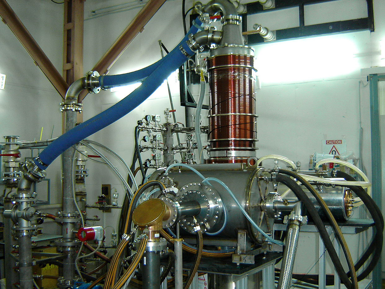
The gyrotron was invented in the 1960s at the Radiophysical Research Institute in the USSR. This is a high-power vacuum device used mainly for heating plasma in nuclear fusion experiments - for example, at ITER , which is now being built in the south of France [an international experimental thermonuclear reactor that will operate according to the tokamak scheme , also invented in the USSR / approx. transl.]. In such experiments, heating up to temperatures of 150 million ° C may be required.
How does a megawatt gyrotron work? It uses beams of high energy electrons spinning in a cavity in a strong magnetic field [gyrate, eng. - rotate in a circle]. The interaction between the spinning electrons and the cavity's electromagnetic field generates high-frequency radio waves that are directed into the plasma. Waves accelerate the electrons in the plasma, thereby heating it up.
A lamp that produces an average of 1 MW of energy will not be shallow. Fusion gyrotrons are typically 2 to 2.5 meters high and weigh on the order of a ton - in particular, thanks to Tesla's 6-7 superconducting coils.
In addition to plasma heating, gyrotrons are used for material processing and in nuclear magnetic resonance spectroscopy . Also, the American army tried to use them to disperse crowds (systemActive Denial System ). The system emits a relatively wide beam of millimeter waves with a diameter of about one and a half meters. The beam should warm up the human skin, causing a burn sensation, but not penetrating into the tissues or causing them to damage.
Traveling wave mini lamp

As the name suggests, a traveling wave tube (TWT) amplifies signals through the interaction between the electric field of a traveling or propagating electromagnetic wave and an electron beam.
Most twentieth-century TWTs were designed with extremely high gains, 100,000 or more. However, such a coefficient is not always needed. Mini TWTs come in handy here, such as the lamp in the photo at the beginning of the L3Harris Electron Devices production section . Its gain is about 1000 (30 dB). It is needed for cases where the output energy is in the range of 40 to 200 watts, and a small size and voltage is required. For example, a 40W mini TWT operating at 14 GHz will fit in your hand and weigh less than 500g.
It turns out that the military has a great demand for mini TWT. Shortly after their appearance in the 1980s, mini TWTs were adopted in electronic warfare, and began to be used on aircraft and ships as protection against missiles with active radar homing . In the early 1990s, developers began integrating mini TWTs into compact high-voltage power supplies. This system became known as the microwave power module (MPM). MPM amplifiers immediately found application in radars and transmitters of military drones such as the Predator and Global Hawk, as well as in electronic protection systems.
Klystron

The klystron helped accelerate progress in high energy physics. Klystrons convert the kinetic energy of an electron beam into radio wave energy. The output power of the device is much higher than that of TWT or magnetrons. Klystron was invented by brothers Russell and Sigurd Varian in the 1930s, and founded in a company with other engineers, Varian Associates to sell instruments. Today this business lives within the framework of Communications and Power Industries.
In a klystron, electrons emitted by the cathode are accelerated towards the anode, forming a beam. The magnetic field prevents the beam from expanding as it passes through the hole in the anode and hits the collector. Hollow structures, cavity resonators are located between the anode and the collector. A high-frequency signal is applied to the resonator closest to the cathode, which leads to the appearance of an electromagnetic field inside the cavity. The field modulates the beam of electrons passing through the resonator, due to which the velocities of the electrons begin to differ, and those, as they move through the resonators, are grouped into bunches. Most of the electrons, passing through the last actively oscillating resonator, slow down. As a result, the output signal is much stronger than the input signal.
In the 1960s, engineers developed a klystron to operate as a source of radio waves in Stanford's new 3.2 km linear particle accelerator . It operated at 2.856 GHz and used a 250 kV electron beam. Its peak power was 24 MW. In total, 240 such klystrons had to be installed to obtain particle energies in the region of 50 billion eV.
These klystrons paved the way for the large-scale use of vacuum tubes as sources of radio waves in particle physics. A 65 MW version of such a klystron is still being produced. Klystrons are also used for screening luggage, food sterilization, and radiation therapy.
Traveling wave tube with ring rod

One of the lamps from the Cold War period that remains in service to this day is a huge traveling wave lamp with a ring rod. This high-energy lamp has a cathode-to-collector distance of more than 3 m, making it the world's largest TWT.
128 ring-rod TWTs provide powerful pulses of radio signals for the extremely powerful phase-array radar based at Cavalier Air Force Base in North Dakota. This radar, operating at 440 MHz, is called the Perimeter Acquisition Radar Attack Characterization System ( PARCS ). He looks out for ballistic missiles flying towards North America. It also tracks space rocket launches and objects moving in orbit, going intospace observation network . PARCS, built in 1972, tracks more than half of all objects in Earth's orbit. It is said to be capable of detecting a basketball-sized object at a distance of 3200 km.
An even higher frequency version of the ring-rod lamp is used in phase-grating radar on the remote island of Shemya, located 1,900 km off the coast of Alaska. This is the Cobra Dane radar , which tracks non-US ballistic missile launches. It also collects observation data from space launches and satellites in low Earth orbit.
This giant's scheme is known as the ring rod. It consists of concentric rings connected by alternating segments, or rods, spaced at equal intervals along its entire length. This scheme gives a higher field intensity along the electron beam compared to ordinary TWT, in which radio waves propagate along a spiral wire. Higher intensities give higher gain and better efficiency. The lamp in the photo was designed by Raytheon in the early 1970s; today they are produced by L3Harris Electron Devices.
Ubitron

Charles Enderby with ubitrons
"free electron laser" Fifteen years before the invention of the term existed vacuum tube operating on the same basic principle - ubitron [ ubitron ], an abbreviation of the undulating beam interaction [undulating beams interaction].
The ubitron was invented by accident in 1957. Robert Phillips, an engineer at the General Electric Microwave Laboratory in Palo Alto, California, was trying to figure out why one TWT in the laboratory exhibited oscillations and the other did not. Comparing the two lamps, he noticed variations in their magnetic focusing, which caused the beam to wriggle in one of the lamps. He realized that these undulating vibrations can cause periodic interactions with an electromagnetic wave in the waveguide. This can be useful for obtaining extremely high peak radio power. And so the ubitron appeared.
Between 1957 and 1964, Phillips and his colleagues collected and tested many ubitrons. The photo at the beginning of the section was taken in 1963 and shows Charles Enderby holding an ubitron without a magnet. The lamp operated at 70,000 volts and delivered 150 kW at its peak at 54 GHz - a record that lasted ten years. However, in 1964, the US Army stopped funding this research because there were no antennas or waveguides that could handle these energies.
Free electron lasers today use the same basic principle as the ubitron. Phillips even won an award in 1992 for his research in the field of such lasers. Today these lasers are installed in large light and X-ray sources in particle accelerators, and emit powerful electromagnetic radiation. It is used to study the dynamics of chemical bonds, photosynthesis, analyze the work of drugs, and to create warm dense matter suitable for studying the formation of gas giants.
Carcinotron
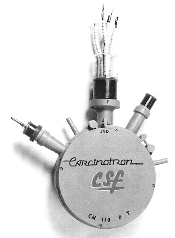
A French lamp called the carcinotron is another interesting example of a device that was born during the Cold War. She is related to the magnetron. It was invented in 1951 by Bernard Epstein from Compagnie Générale de Télégraphie Sans Fil (CSF), now part of Thales.
The carcinotron, like the ubitron, emerged from an attempt to solve the problems with the oscillation of a conventional lamp. In this case, the source of the oscillations was the supply wave going in the direction opposite to the direction of the electron beam. Epstein discovered that the frequency of oscillations can be regulated by voltage, as a result of which a patent appeared for a backward-wave lamp , regulated by voltage [the idea of creating a BWO was expressed in 1948 by the Soviet scientist MF Stelmakh / approx. transl.].
For 20 years, electronic jammers used in the USA and Europe have used the carcinotron as a source of radio waves. The lamp in the photo was one of the first ones produced by CSF in 1952. It delivered 200 watts in the S band, from 2 to 4 GHz.
Carcinotrons are quite compact when you consider their power output. Together with the permanent focusing magnet, the 500 W model weighs 8 kg and measures 24 × 17 × 15 cm, slightly smaller than a shoebox.
The strange name comes from the Greek word karkunos, meaning crayfish, Phillippe Touvenin, a vacuum electronics specialist at Thales Electron Devices, explained to me. After all, crayfish move backwards.
Dual-mode traveling wave lamp
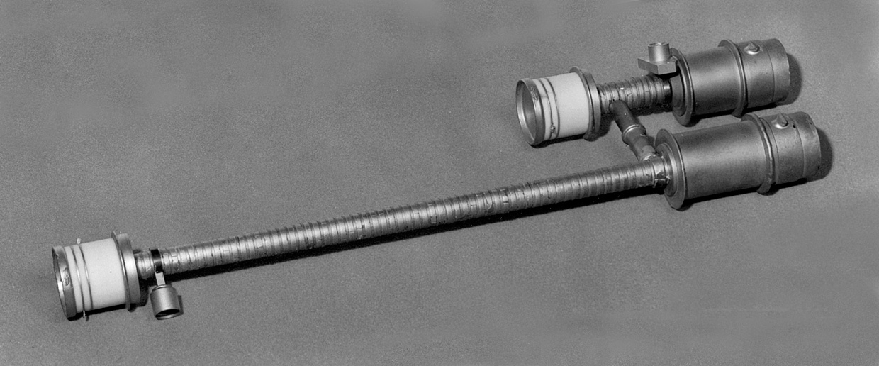
The dual-mode TWT was a bizarre microwave vacuum tube developed in the United States in the 1970s and 1980s as a countermeasure to radars. The lamp could produce a continuous wave of low power and an intermittent wave of high power, and in total it had two: two beams, two circuits, two electron guns, two focusing magnets, two collectors - all in a single lamp housing.
Its main advantage was the expansion of the capabilities of the devices - for example, the counter system could operate in two modes, with a continuous low-power wave and an intermittent high-power wave, but with a single transmitter and a simple antenna feed. The control grating of the electron gun in the short section of the lamp, which was responsible for intermittent waves, could quickly switch the lamp modes. Naturally, if the lamp housing was damaged, both functions ceased to work.
The lamp in the photo was developed by Raytheon, which was bought by Litton Electron Devices in 1993. Raytheon / Litton and Northrop Grumman made dual-mode TWTs, but their production was too complex for mass production, so it was phased out in the early 2000s.
Multi-beam klystron
Power, as many of us have learned as students, is voltage times current. To extract more power from the vacuum tubes, you can increase the voltage across the electron beam, but you have to increase the tube size and complicate the power supply. You can also raise the beam current, but there are enough problems with this. You will need to make sure that the device can handle the higher current and that the magnetic field can safely move electrons around the circuit — the part of the lamp that interacts with the electron beam.
In addition, the efficiency of a lamp usually decreases with increasing current as the electron bunching required for energy conversion is impaired.
All of these disadvantages appear in a conventional vacuum tube with a single electron beam and a single circuit. But what if we organize several beams outgoing from several cathodes, but passing through a common circuit? Even if the individual beams are of average power, the total current will be large and the efficiency of the device will not be affected.
Such multi-beam devices were studied in the 1960s in the USA, the USSR and many other places. In the United States, this did not work out, but in the USSR, work continued, and led to the successful introduction of multi-beam klystrons, or MLK. In Russia, many of these lamps have been used and are used in various fields, including for radars.
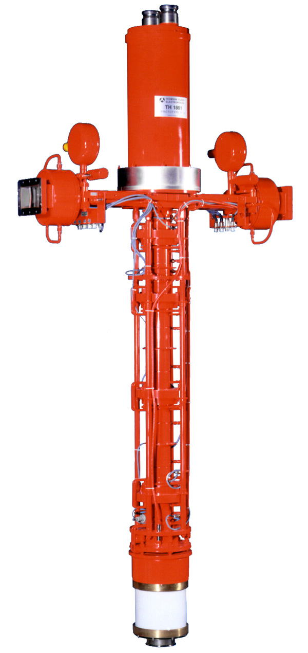
The photo shows a modern example of an MLK manufactured in 2001 by the French company Thomson Tubes Electroniques (now part of Thales ). It was developed in the German laboratory Electron Synchrotron ( DESY ). A newer version is used in the European laboratory for X-ray free electron lasers . The lamp uses seven beams, giving a total current of 137 A, with a peak power of 10 MW and an average of 150 kW. Its efficiency exceeds 63%. In comparison, the Thomson single-beam klystron delivers 5 MW of peak power and 100 kW of average power, with an efficiency of 40%. It turns out that in terms of signal amplification, one MLK is equivalent to two conventional klystrons.
Coaxitron
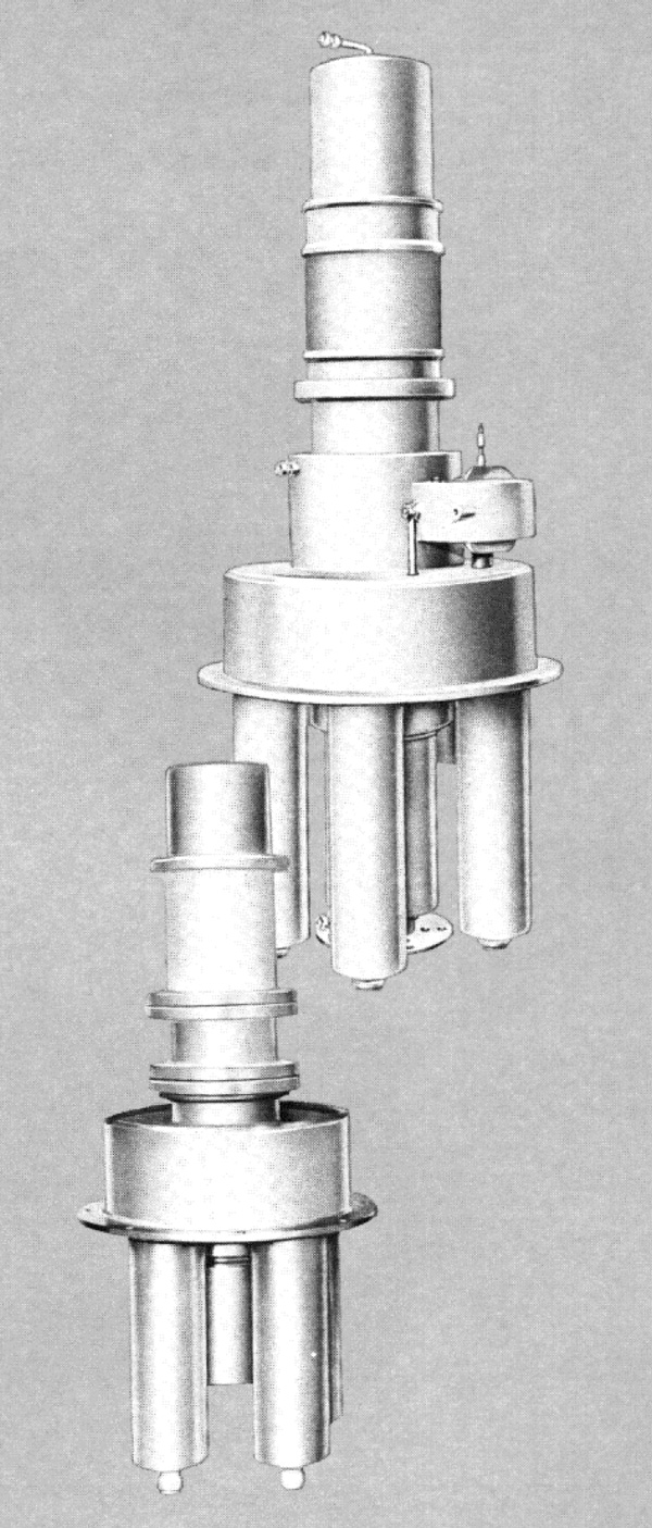
All the lamps I've described use electron beams. However, before the appearance of such devices, grids were used in lamps - electrodes in the form of transparent metal screens. They were placed between the cathode and anode to control or modulate the electron flow. Depending on the number of such grids, the lamps were called diodes (without grids), triodes (with one grid), tetrodes (two grids), etc. Low wattage lamps were called "receiving lamps" because they were commonly used in radios or as switches (note that lamps are called "tubes" in the US and "valves" in Britain).
Of course, they also made lamps with control grids that support high powers.... Transmitting lamps have been used - yes, yes - in radio transmitters. Later, such lamps began to be used in a variety of interesting areas in industry, science and military affairs.
In triodes and lamps with even more grids, there was a cathode, a grid controlling the current, and an anode or collector (or plate). Most of them had a cylindrical shape with a central location of the cathode - usually it was a thread surrounded by electrodes.
The Coaxitron, developed by RCA in the early 1960s, is a unique modification of the cylindrical design. The electrodes run along a radius, from the cylindrical coaxial cathode to the anode. However, at the coaxitron cathode, the electron emitter is not the only one - it is located in segments along the entire circumference, and many heated filaments serve as sources of electrons. Each thread gives its own small beam of electrons. Since this beam travels radially to the anode, no magnetic field is required to limit the electron flow. Therefore, the coaxitron turns out to be very compact, given the significant level of its power, on the order of a megawatt.
The 1 MW 425 MHz coaxitron weighed 59 kg and was 61 cm long. Although it had a rather modest gain, 10 to 15 dB, as a compact and ultra-high frequency amplifier, it was a unique device. RCA wanted to make an accelerator on such devices, but in the end they took root in UHF radars. And although solid-state devices have recently taken the place of coaxitrons, some of them still work in old radar systems.
Audio tube Telefunken

An important example of a lamp whose grids are at the opposite end of the power and frequency spectrum compared to megawatt monsters such as the klystron or gyrotron. The Telefunken VF14M was respected by audio engineers and musicians as it was used as an amplifier in the legendary Neumann U47 and U48 microphones . They were preferred by Frank Sinatra and Beatles producer George Martin. By the way, the Neumann U47 microphone is kept in the Abbey Road studio museum in London. The letter M in the name of the lamp indicates that it is suitable for use in microphones. Only lamps tested by Neumann received this part number.
VF14 is a pentodethat is, it has five electrodes, three of which are grids. However, in a microphone it works like a triode, and two of the three grids are connected together and connected to the anode. This is due to the supposedly better sound quality of the triodes. The VF14 filament, which heats the cathode to emit electrons, operates at 55 V. This was done on purpose so that two lamps could be daisy-chained at 110 V, reducing the cost of the power supply - an important factor in post-war Germany.
Today you can buy chips that replace the VF14M, and even emulate a 55V filament. But will they replace the warm tube sound? Audio snobs, of course, would never agree with that.