In the previous part of the article, we examined the stage of starting the system design. Now I want to tell you what kind of device came out in the end.
Part 1
Part 2
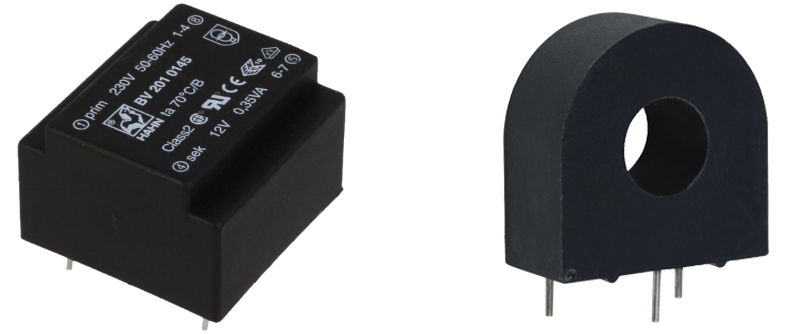
In the discussion of the first part, the issue of measuring voltage and current was raised. So I decided to cover it in more detail. As I wrote earlier, the voltage and current sensors in our circuit are transformers. A miniature transic BV 201 0145 is used to measure the voltage, and for the AC-1020 current sensor:

The voltages are removed from them, which are digitized by the ADC built into the microcontroller. The analogue part is shown below:

The current sensor is loaded across resistor R3. Zener diode VD3 protects against sudden voltage surges caused by short current surges. Resistors R2, R4 set the "zero point" around 1.8V. The same is done for the voltage transformer. Only there is a divider on resistors R8 and R10, since the transformer in our case produces a nominal voltage of 12 V.
We carry out digitization at a frequency of 1000 Hz for 200 ms. Based on the obtained values, we calculate the RMS. We do a quick calculation of the squared values right in the interrupt. After 200 samples have been accumulated in the main program loop, the final calculation is performed using floating point numbers.
Why you need to measure RMS and how best to do it is well described here in this article .
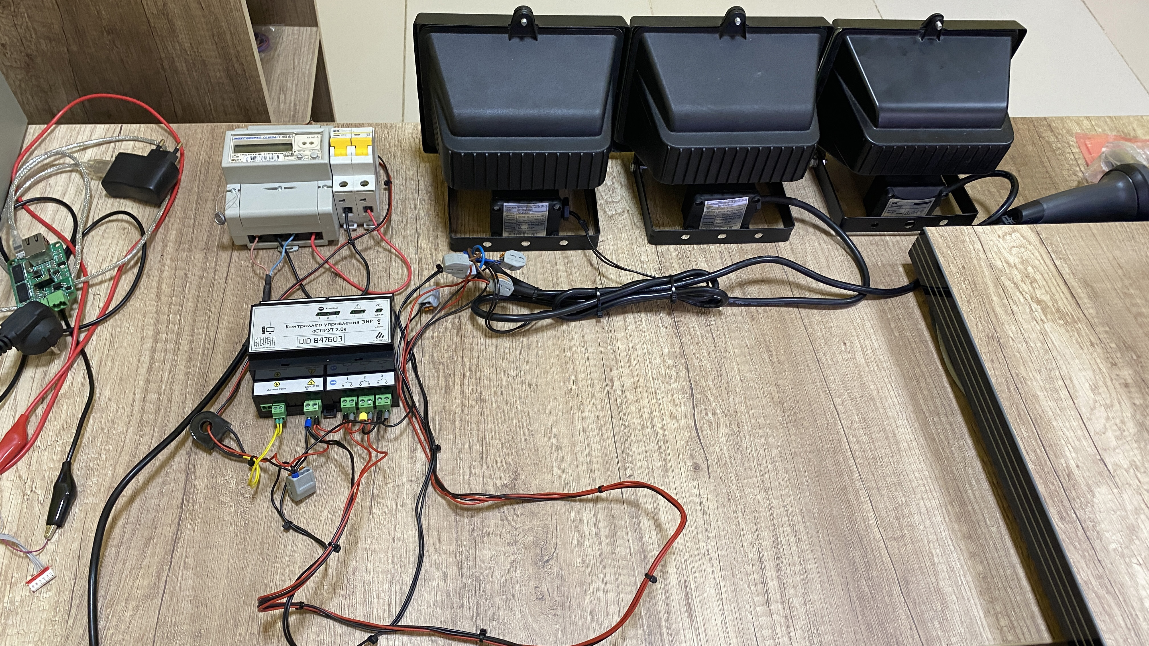
I have already written more than once that when developing our devices, we always try to use the most common electronic components to the maximum, in order, on the one hand, to reduce the cost, and on the other hand, not to have problems with their supply during the production of the series. In this design, all resistors used have a 5% tolerance. Naturally, due to such an error, the products after production had a large error when measuring voltage and current. This error was eliminated on an automated calibration bench. The "stand", of course, sounds a little loud, but it performs its function as it should. The stand consists of the following components:
- Set of three 500 W halogen lamps
- Current sensor described above
- Electricity meter Energomera CE102M
- USB-RS-485 converter
- Circuit breaker
We use the meter as an exemplary meter for mains voltage and load current. The CE102M model is very convenient because, firstly, it is connected with just two wires to the USB-RS-485 converter (there is its own power converter inside the meter), and, secondly, it does not require entering the serial number to read the data. It seems like a trifle, but they add convenience in using the counter.
The exchange protocol is well described in the manufacturer's manual. So there were no difficulties with software implementation.
By the way, you can write a separate small article on counters. At one time, I worked closely with them, as a result, some of our devices support four popular models: Incotex-SK "Mercury 206", Energomer "CE102", Energomer "CE102M" and IEK "STAR 104/1".
The general view of the stand turned out as follows:

For automation, a simple program was developed that reads data from the meter, controls the built-in relays of the controller and automatically selects the coefficients for the current and voltage meter:
We usually use barcodes for the serial numbers of our devices. It is very convenient to enter them using a barcode scanner:

But in this case, the device was ordered, and the customer asked to execute the serial simply in the form of large numbers on the front panel.
The calibration program saves all data in our internal system. It records who, when what was checked and the corresponding list of parameters. The most important ones are the serial number and MAC address.
By the way, about the MAC addresses. We buy them in the form of Microchip's 24AA025E48-I / SN chips. When purchased in bulk, they are inexpensive and very easy to use. The MAC address is read over the I2C interface.
Now for the connection with the server. At the beginning of development, we already had the main functionality. It is a simple web service written in ASP.net and a separate server program for communicating with the hardware. Each controller transmits a data packet via UDP protocol once a minute. The server software parses it, stores the data in the database (with "decimation" up to once an hour) and additionally remembers the external IP address and port from which the packet came. This is needed to control the controller from the server.
Since, in fact, 100% of devices are located behind NAT, it is necessary to take into account some peculiarities. The main one is that some NATs have a small timeout for allocating an external port to the client (less than a minute). The percentage of such, according to our statistics, is not very large, but in any case, this leads to the need to reduce the interval for sending monitoring data from the controller to the server to "maintain" the dedicated port.
I'll write right away why we use UDP and not TCP connection, although our device, of course, has an implementation of both protocols. The choice of UDP is justified only by the ease of use and low computational costs from both the controller and the server side. Yes, it does not guarantee the delivery of data packets, but you need to understand that this is easily implemented by a higher layer protocol that runs on top of UDP. In addition, when transmitting monitoring data, the loss of several packets per day is absolutely insignificant, especially considering that when saving to the database, we still "thin out" and save the data only once an hour. But when the controller is remotely controlled, for example, when the relay is turned on / off in manual mode, the request-response system works and several attempts to send a command are made.
In addition, through the server we have implemented a remote update of the "firmware" of the controllers. It also works over UDP. True, the update works in a semi-automatic mode. All the same, it is not good to run it in the machine at an arbitrary moment, since this can lead to a problem in the work of end users. Imagine how surprised they will be if in broad daylight the Ethernet relay disconnects some load and restarts :-)
In conclusion, I would like to say that over the past two years we have produced almost a thousand of these devices. All of them are online. About two thousand other controllers also constantly communicate with our server. In general, everything works quite steadily. Although, of course, we are constantly expanding the functionality. For example, we recently released a mob. application for remote control of our devices via the Internet. But write about him sometime next time ...