Today I will show you how to assemble a case for the Raspberry Pi 4, which turns a raspberry into a real mini-computer.
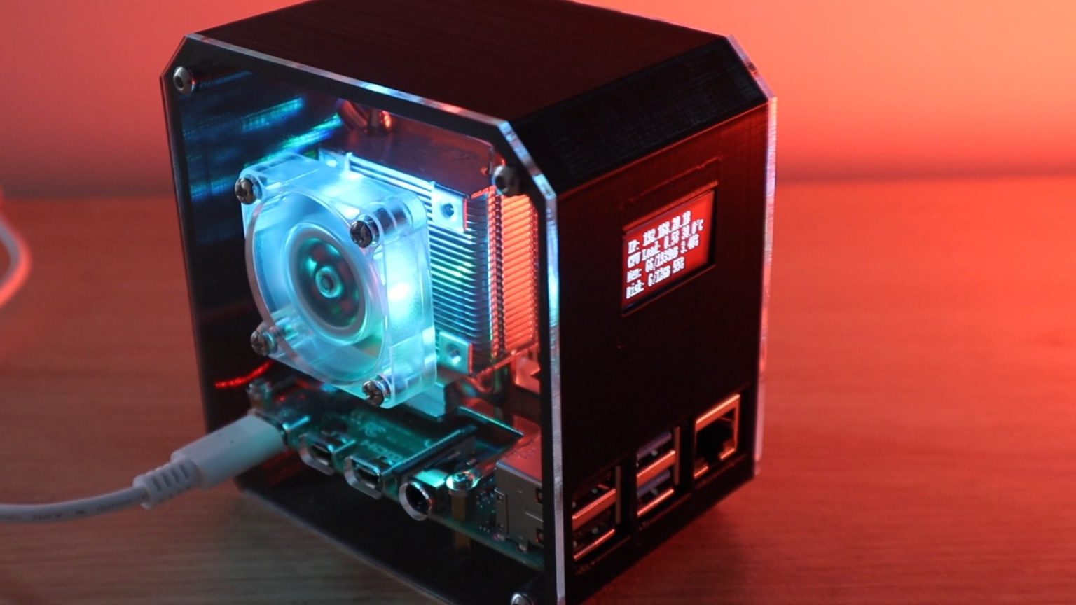
The case is partly 3D printed, partly made of transparent acrylic, so you can see the "insides" of our mini-PC. To cool the processor, I used an Ice Tower cooler, but I did not attach the fan to the radiator, but to the box wall.
I also built an OLED display into the front of the case, which displays the Raspberry's IP address and data such as CPU performance and temperature, storage and memory usage.
Here is a video of the assembly, case and display:
What you need to create your own Raspberry Pi 4 mini desktop computer

- Raspberry Pi 4 (any model will do)
- Micro SD card;
- Raspberry Pi power supply;
- Cooler Ice Tower;
- I2C OLED display;
- Ribbon cable;
- Female male connector;
- Mounting screws;
- Acrylic 2mm;
- Black plastic for 3D printer (PLA).
You will also need a 3D printer to print the plastic part of the case. I'm using the Creality Ender 3 Pro, which I think combines affordability and quality.
No laser engraver is required for assembly, although it makes it much easier to manufacture body parts. They can always be simply cut by hand using your existing tools, or you can use a laser cutting service. I used a K40 desktop laser engraver.
Let's assemble our Raspberry Pi 4 case
We print the body on a 3D printer
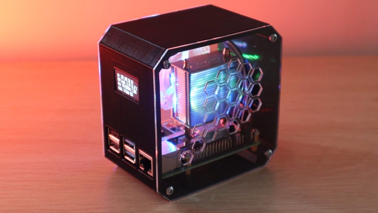
I started by creating a 3D model of the future boxing in Tinkercad .

Download the model
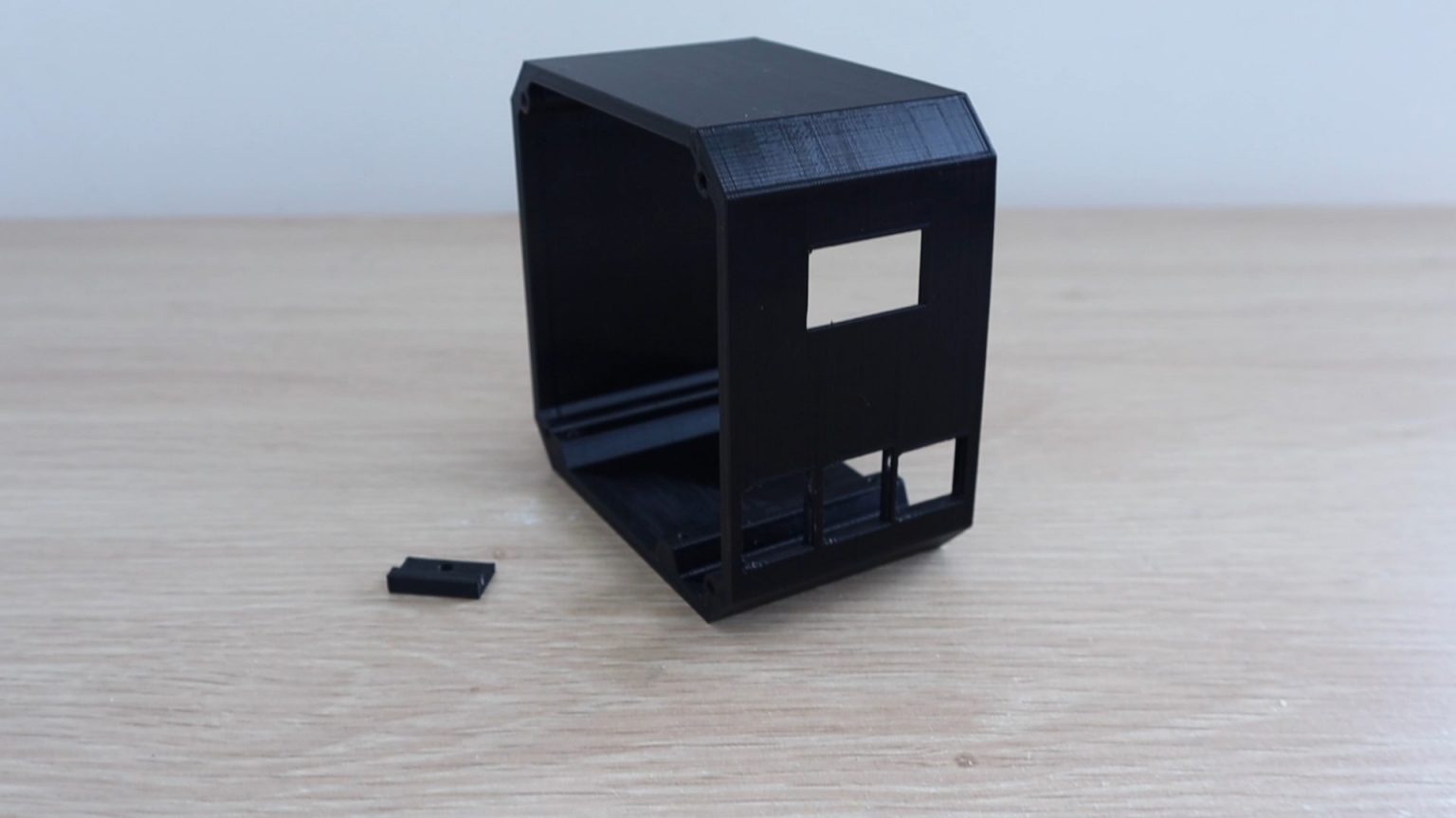
Developed a case model taking into account the intended placement of the Raspberry Pi inside the box. According to the plan, USB and Ethernet ports are available on the front, while power, HDMI and audio ports are on the back.
The OLED display is located on the front of the case, above the ports. At the top we will fix it with two small clips, at the bottom - with a plastic clip with a screw. I have previously used this method when creating an Arduino based reaction timer .
I will install the "raspberry" on the brass racks that came with the Ice Tower. I just added a few M2.5 holes.
I don't often pull my SD card out of the raspberry, so I didn't add a cutout to make it easier to remove. If you plan on doing this, just add a round cutout to the back of the case. Replacing the SD card without this cutout will be a little more difficult as you will need to first remove your single board computer from the box.
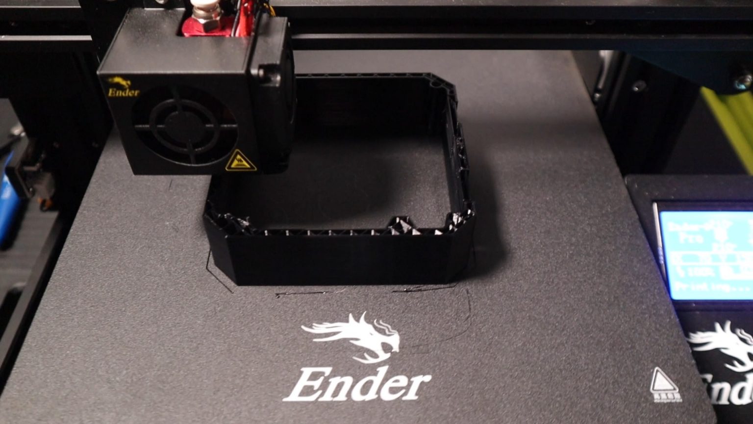
I 3D printed our mini-computer case made of black plastic with a layer height of 0.2 mm and 15% coverage. At the same time, I took into account the cutouts for the display and ports on the front panel when printing. This can be done easily in a 3D modeling program. You will also need to print a small plastic display clip.
Embedding Raspberry Pi and cooler
Now that the main body of the case is ready, let's install the Raspberry Pi into it. First, screw the brass posts into the holes in the base.

Note that I have changed the orientation of the screws and feet that come with the Ice Tower so that they screw directly into the bottom of the case and do not require through holes. If you study the Ice Tower manual, you will notice that the stands and screws are reversed.

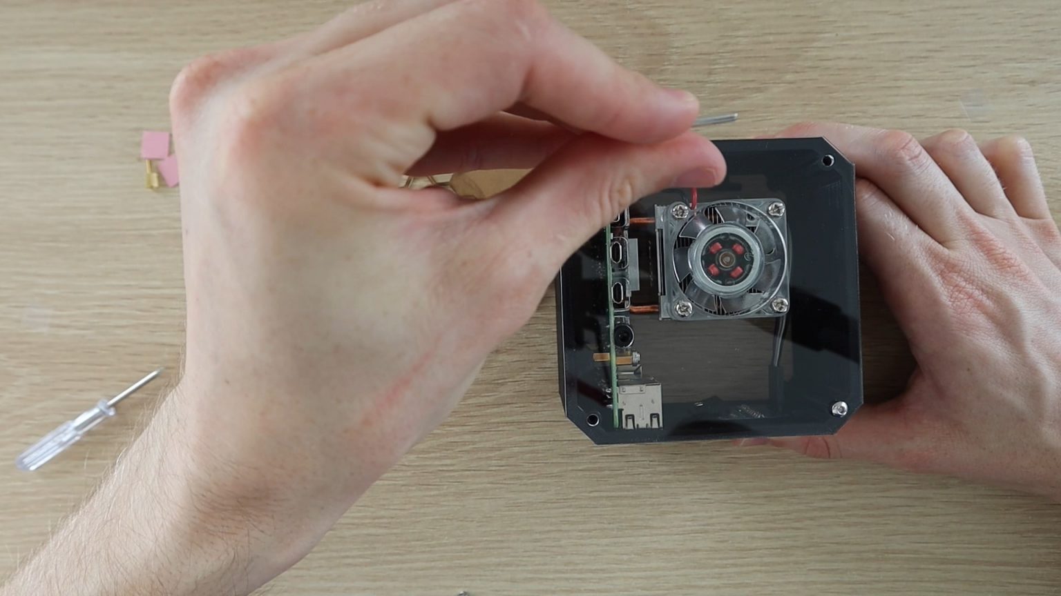
We need to remove the fan from the cooler so that we can attach it to the transparent side panel. We put the fan right here to make sure cool air is drawn in from the outside of the case and then expelled through the vents on the opposite side.
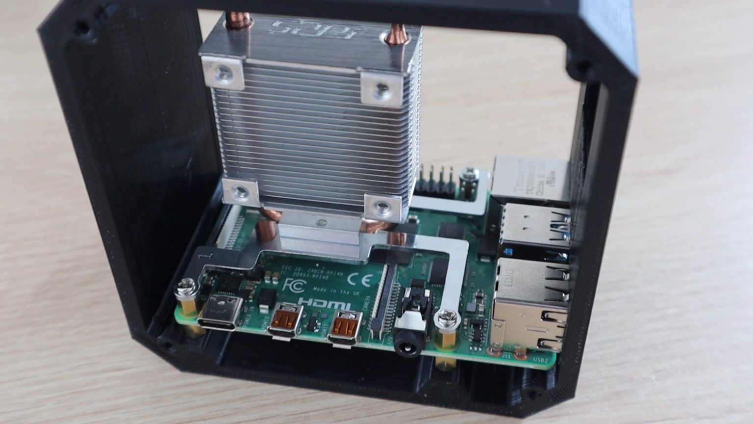
Install the support brackets to the bottom of the Ice Tower radiator according to the instructions. Make sure you are doing everything right.
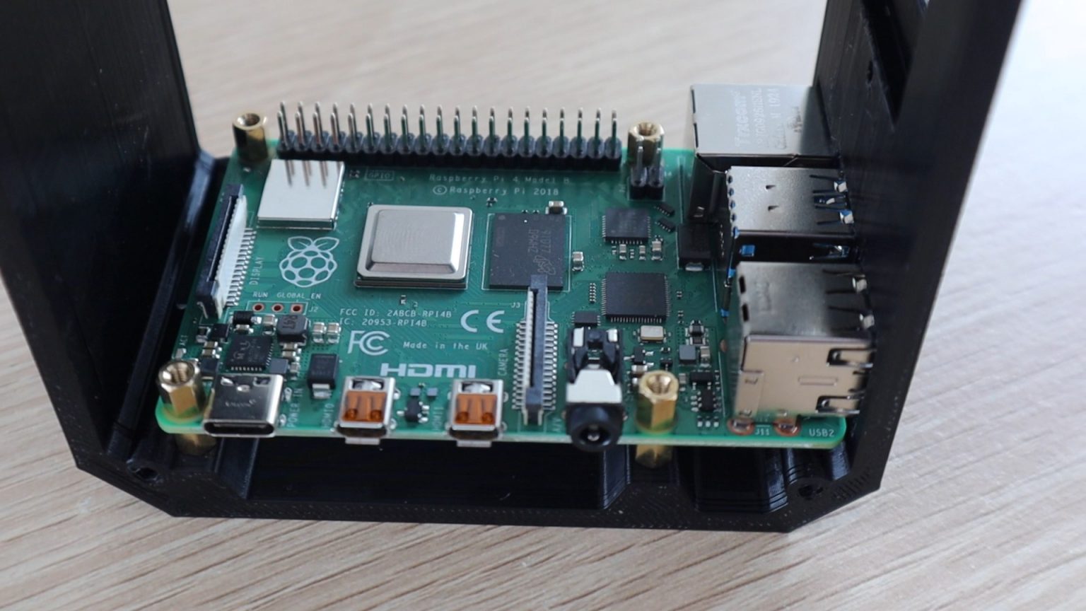
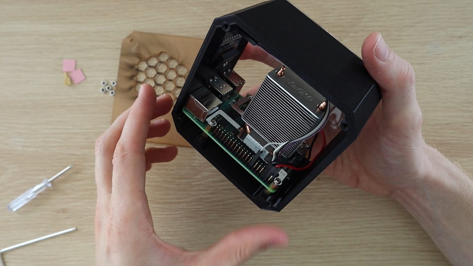
Place the "raspberry" in its place, and then use the second set of brass posts screwed into the "bottom" of the case to secure everything.

Glue the heatsink pad to the processor and remove the top protective film. Place the Ice Tower heatsink on the heat pad on the processor and secure it with four screws in the brass stands.
Installing the OLED display
Now we need to install the OLED display. If your display pins are not soldered, solder them to the back of the display.
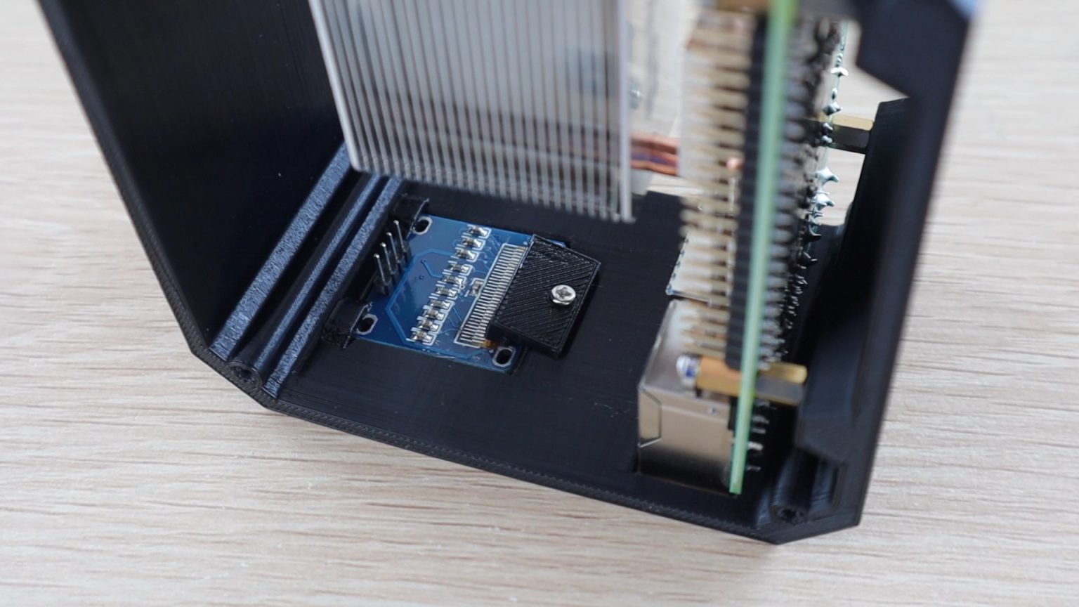
Slide the top edge of the display under the plastic clips, and then gently push it into place.
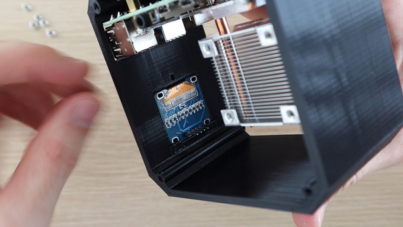
Use the clip we 3D printed and secure it with a small screw. A flexible shaft or 90 degree angle screwdriver may be required to tighten the screw.
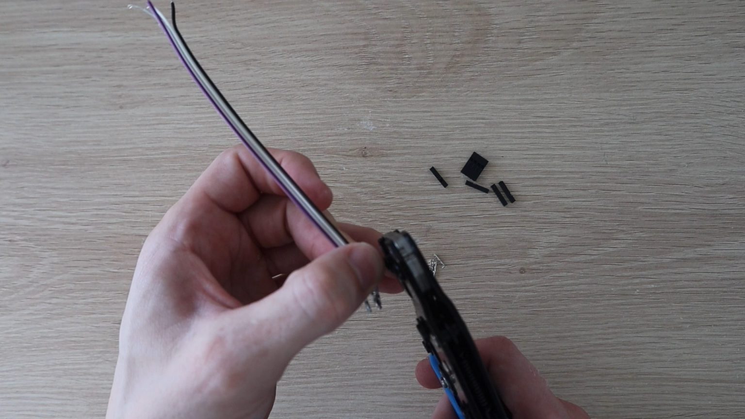
Now we need to lead the wires to the OLED display. You will need to make 4 connections to the General Purpose I / O Interface (GPIO) pins - two for power and two for communications. I made a short jumper cable from DuPont connector pins and ribbon cable. You can also use multiple breadboard pins or jumpers to connect the display to your Malinka.

When the cable is assembled, connect one side of the cable to the back of the display and the other to the GPIO pins as follows:
- VCC → Pin1 3.3V Power;
- GND → Pin14 Ground;
- SCL → Pin3 SCL;
- SDA → Pin2 SDA.

I noticed that there are two versions of these OLED displays, the order of placing the contacts in them is slightly different. So just make sure you connect the power to the correct pins.
We make acrylic walls
In general, we are done with the inner parts of our case. Now let's make some acrylic walls to complete it.

I reopened Tinkercad (free 3D modeling software - ed.) And roughly figured out where the Ice Tower radiator should be, so that the fan mounting holes were in the right place on the side panels. Then I exported an image of the case walls to open in Inkscape and draw a laser engraving layout.
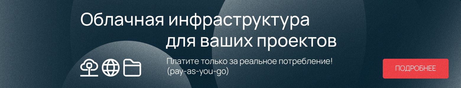
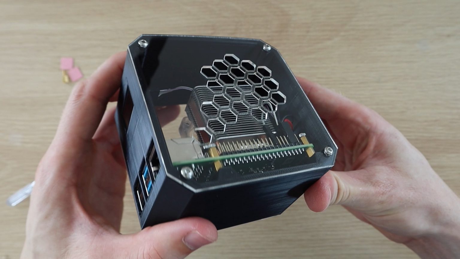
We make two acrylic walls: one with a fan for intake air, the other with openings for exhaust air.

You can remove the outline of the part, since we only need to cut the outline of the wall and the holes in it. In general, the model needs to include a fan hole and four screw holes. It is also important to add holes to secure the acrylic wall to the previously printed case.

Then I duplicated the shape of the wall where the fan will be installed and draw a series of hexagons in place of the hole. The logic is simple: hexagons are for the exhaust air flow.

Download a model of acrylic walls
Download a model of a part of the case for 3D printing
If you do not have a laser machine for such precise and complex cutting, simply drill round holes (about 8 mm in diameter) in the same place.

We cut! For the side panels I used 2mm clear acrylic.

You can use any acrylic you want - translucent tinted or opaque. The most available plexiglass is 3 mm thick. Overall, the thickness doesn't really matter, you just have slightly thicker edges.
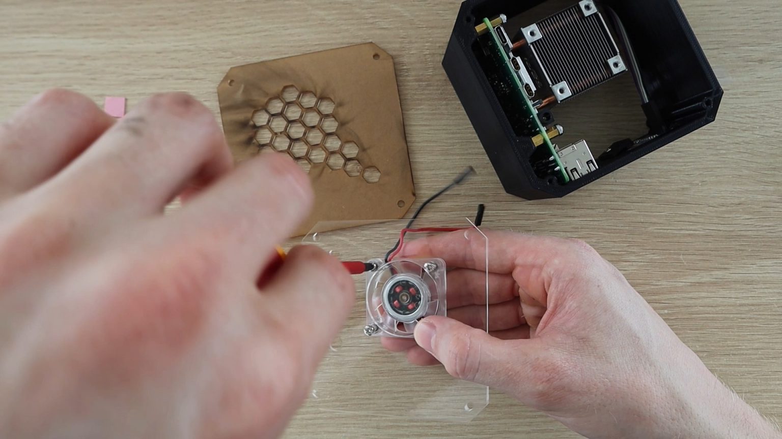
To mount the fan to the side panel, press several M3 nuts into the corresponding slots. The easiest way is to place the nut on a flat surface, position the desired hole over it to secure the fan, and press until it snaps into place. The nuts will hold tight, so you don't have to use a wrench to hold them while tightening the screws.
If you want to use fan screws, I will tell you straight away that they will be too short to fit through the acrylic, fan and nut. It is also not the best way to attach a fan.
Screw the side glass to the 3D printed case with four M3 x 8mm hex head screws.

This will be tricky because there are no threads inside the holes in the printed case.
Now connect the fan to a 5V power supply and install the second acrylic panel (with exhaust holes). Red wire to Pin4 (5V) and black wire to Pin6 (Ground).
This completes the assembly. Our Raspberry Pi 4 mini desktop is ready. Now we need the display to work.
Programming the OLED display
For the display to work, you need to run a Python script. To do this, you need to run the "raspberry".
The Raspberry Pi communicates with the display using the I2C protocol, so make sure to take this into account in your settings. Also check if you have python-smbus and i2c-tools libraries installed. They should be by default, but here it is better to override and still check.
The script below is based on one of the scripts in the Python Adafruit library for OLED display modules with some modifications made by Shahizat Nurgaliev to add CPU temperature to the displayed data and change the display format.
# Copyright (c) 2017 Adafruit Industries
# Author: Tony DiCola & James DeVito
#
# Permission is hereby granted, free of charge, to any person obtaining a copy
# of this software and associated documentation files (the "Software"), to deal
# in the Software without restriction, including without limitation the rights
# to use, copy, modify, merge, publish, distribute, sublicense, and/or sell
# copies of the Software, and to permit persons to whom the Software is
# furnished to do so, subject to the following conditions:
#
# The above copyright notice and this permission notice shall be included in
# all copies or substantial portions of the Software.
#
# THE SOFTWARE IS PROVIDED "AS IS", WITHOUT WARRANTY OF ANY KIND, EXPRESS OR
# IMPLIED, INCLUDING BUT NOT LIMITED TO THE WARRANTIES OF MERCHANTABILITY,
# FITNESS FOR A PARTICULAR PURPOSE AND NONINFRINGEMENT. IN NO EVENT SHALL THE
# AUTHORS OR COPYRIGHT HOLDERS BE LIABLE FOR ANY CLAIM, DAMAGES OR OTHER
# LIABILITY, WHETHER IN AN ACTION OF CONTRACT, TORT OR OTHERWISE, ARISING FROM,
# OUT OF OR IN CONNECTION WITH THE SOFTWARE OR THE USE OR OTHER DEALINGS IN
# THE SOFTWARE.
import time

import Adafruit_GPIO.SPI as SPI
import Adafruit_SSD1306

from PIL import Image
from PIL import ImageDraw
from PIL import ImageFont

import subprocess

# Raspberry Pi pin configuration:
RST = None     # on the PiOLED this pin isnt used
# Note the following are only used with SPI:
DC = 23
SPI_PORT = 0
SPI_DEVICE = 0

# Beaglebone Black pin configuration:
# RST = 'P9_12'
# Note the following are only used with SPI:
# DC = 'P9_15'
# SPI_PORT = 1
# SPI_DEVICE = 0

# 128x32 display with hardware I2C:
disp = Adafruit_SSD1306.SSD1306_128_32(rst=RST)

# 128x64 display with hardware I2C:
# disp = Adafruit_SSD1306.SSD1306_128_64(rst=RST)

# Note you can change the I2C address by passing an i2c_address parameter like:
# disp = Adafruit_SSD1306.SSD1306_128_64(rst=RST, i2c_address=0x3C)

# Alternatively you can specify an explicit I2C bus number, for example
# with the 128x32 display you would use:
# disp = Adafruit_SSD1306.SSD1306_128_32(rst=RST, i2c_bus=2)

# 128x32 display with hardware SPI:
# disp = Adafruit_SSD1306.SSD1306_128_32(rst=RST, dc=DC, spi=SPI.SpiDev(SPI_PORT, SPI_DEVICE, max_speed_hz=8000000))

# 128x64 display with hardware SPI:
# disp = Adafruit_SSD1306.SSD1306_128_64(rst=RST, dc=DC, spi=SPI.SpiDev(SPI_PORT, SPI_DEVICE, max_speed_hz=8000000))

# Alternatively you can specify a software SPI implementation by providing
# digital GPIO pin numbers for all the required display pins.  For example
# on a Raspberry Pi with the 128x32 display you might use:
# disp = Adafruit_SSD1306.SSD1306_128_32(rst=RST, dc=DC, sclk=18, din=25, cs=22)

# Initialize library.
disp.begin()

# Clear display.
disp.clear()
disp.display()

# Create blank image for drawing.
# Make sure to create image with mode '1' for 1-bit color.
width = disp.width
height = disp.height
image = Image.new('1', (width, height))

# Get drawing object to draw on image.
draw = ImageDraw.Draw(image)

# Draw a black filled box to clear the image.
draw.rectangle((0,0,width,height), outline=0, fill=0)

# Draw some shapes.
# First define some constants to allow easy resizing of shapes.
padding = -2
top = padding
bottom = height-padding
# Move left to right keeping track of the current x position for drawing shapes.
x = 0


# Load default font.
font = ImageFont.load_default()

# Alternatively load a TTF font.  Make sure the .ttf font file is in the same directory as the python script!
# Some other nice fonts to try: http://www.dafont.com/bitmap.php
# font = ImageFont.truetype('Minecraftia.ttf', 8)

while True:

    # Draw a black filled box to clear the image.
    draw.rectangle((0,0,width,height), outline=0, fill=0)

    # Shell scripts for system monitoring from here : https://unix.stackexchange.com/questions/119126/command-to-display-memory-usage-disk-usage-and-cpu-load
    cmd = "hostname -I |cut -f 2 -d ' '"
    IP = subprocess.check_output(cmd, shell = True )
    cmd = "top -bn1 | grep load | awk '{printf \"CPU Load: %.2f\", $(NF-2)}'"
    CPU = subprocess.check_output(cmd, shell = True )
    cmd = "free -m | awk 'NR==2{printf \"Mem: %s/%sMB %.2f%%\", $3,$2,$3*100/$2 }'"
    MemUsage = subprocess.check_output(cmd, shell = True )
    cmd = "df -h | awk '$NF==\"/\"{printf \"Disk: %d/%dGB %s\", $3,$2,$5}'"
    Disk = subprocess.check_output(cmd, shell = True )
    cmd = "vcgencmd measure_temp |cut -f 2 -d '='"
    temp = subprocess.check_output(cmd, shell = True )

    # Write two lines of text.

    draw.text((x, top), "IP: " + str(IP,'utf-8'), font=font, fill=255)
    draw.text((x, top+8), str(CPU,'utf-8') + " " + str(temp,'utf-8') , font=font, fill=255)
    draw.text((x, top+16), str(MemUsage,'utf-8'), font=font, fill=255)
    draw.text((x, top+25), str(Disk,'utf-8'), font=font, fill=255)

    # Display image.
    disp.image(image)
    disp.display()
    time.sleep(.1)
Download script for OLED display
You will need to download the original Adafruit library from Github to complete the setup by following these steps.
Open a new terminal window, then change to the library directory:
cd Adafruit_Python_SSD1306Install the library for Python 3:
sudo python3 setup.py installThen you can run the above stats.py file or the sample stats.py file in the Adafruit directory - in which case you just end up with a slightly different display layout.
Change to the directory containing the stats.py script:
cd examplesExecute the script:
python3 stats.pyI recommend testing the script to make sure the display works without errors before setting it to start automatically.
To configure the automatic launch of the script, you need to find the directory of the script, then open crontab and add a line to start it:
@reboot python3 /home/pi/stats.py &Obviously, you will need to change the name of the / home / pi / directory to highlight the one where you saved the desired script.
Don't forget to add & at the end, this will tell Malinka to continue running and run the script in the background.

Reboot your Raspberry Pi to run the script automatically. After that, you should see the indicated statistics on the OLED display when you start up your mini PC.