Subscriber terminal
A subscriber terminal is an individual station installed at a stationary facility (house) and designed to serve one subscriber (account). That is, everyone living in the house can use the Internet, which is distributed via Wi-Fi, but this will be one billing bill. And the likelihood that SpaceX will organize group access or several accounts to one terminal in the near future, I estimate as very low.
In 2016, in the documents sent by Space X to the FCC (see apps.fcc.gov/els/GetAtt.html?id=197812&x= ) 5 types of subscriber terminals were declared. In the table below, these are Models A, B, C, D. E
The first 2 columns refer to earth stations for satellite control and monitoring tasks, and the last five are subscriber terminals


Today, the design of the ES-A model is known. Model ES-B, judging by the magnitude of the beam angle, should have had a larger antenna diameter, and perhaps due to its larger size relative to Model A with an antenna diameter of 48 cm, it was found unsuitable for the mass consumer market and possibly higher cost. Model B may be sized to match the phased array flat antennas found on the StarLink satellite. Models with parabolic antennas have not yet been presented to the public and may be developed later.
As we can see in the StarLink network, the subscriber terminal can work with downlink channels of 5 nominal widths of 15.30.60, 120 and 240 MHz, allowing to transmit 15.30, 60, 120 and 240 Mega-symbols, respectively.
Technical parameters of the subscriber terminal: according to the Space X application sent to the Japanese regulator in 2020, the main parameters of the terminal have not changed since the first application was filed with the FCC in 2016:

That is, the outer diameter of the antenna is 55 cm, its gain G / T is 9 dB / K, the maximum speeds are 350 Mbit from the Internet, and 130 Mbit from the terminal to the Internet. It follows from the table that the terminal operates in a channel (inroute) with a bandwidth (channel width) of 60 MHz. Effective antenna diameter 48 cm, antenna beam angle 2.8 degrees, maximum terminal antenna gain 34.6 dBi, maximum EIRP (EIRP) is 38.2 dBW.

The transmitter power of the subscriber terminal changes depending on its inclination relative to the line to the zenith. In the case when the antenna beam is directed to the zenith, the power delivered to the antenna is 0.76 W, with a maximum deviation from the vertical of 4.06 W. The limitation here is set by the US sanitary standards for the radio flux density, where the parameters of the Space X terminal are only 1% lower than the permitted level for an installation that does not require the involvement of professional installers.
Thus, we can conclude that the spectral efficiency of receiving a subscriber terminal at 240 MHz is quite low, the channel width is transmitted through it no more than 350 Mbit, that is, 1.5 bits / hertz. This is most likely due to the small diameter of the antenna itself and the inherent low area utilization of phased array antennas.
Also, as shown above, in one of SpaceX's letters, the following table was given:

Modulation data, especially on the space-to-Earth link, is most likely given "with optimism", because 64QAM is 6 bits per symbol, and not 1.5, which characterizes the current version of the subscriber terminal, but the data on the antenna pattern ( especially installed on a satellite) are very helpful in understanding how the Starlink network will work.
The subscriber terminal consists of two parts. Antenna with a diameter of 48 cm with a phased array, which is installed outside the home so as to have the most open view of the sky at all 360 degrees:

The photo shows one of the first versions of the StarLink subscriber terminal.
The antenna is connected to the power supply unit via a cable with an Ethernet connector, which also serves as a power cable (PoE technology, power over Ethernet).
Here is a photo of the terminal from November 1, 2020, when public beta testing began.
Apparently, the antenna has an external plastic coating such as a casing, a photo of the terminal located at the Boca Chica test site in Texas appeared on the network on October 12, where this casing could not withstand local climatic conditions and began to collapse:

The house has a Wi-Fi router and a power supply.
In the video below, the first display of the terminal from the employee's home
Figure: The router is in the hand of a SpaceX employee, in the background is an antenna (looks like a white round table on one black leg).
Since the appearance of the router until October 27, 2020 was classified information, the best quality photos appeared only after this date.
Here is the brand nameplate on the router:

Routers are manufactured in Taiwan, and antennas are manufactured in the USA, by SpaceX itself.
Another element of the terminal kit will be a power supply unit that provides both a router and an antenna.


One of the first testers measured the power consumption of the StarLink terminal when it was running on a car battery, the power consumption was 116 W. It is also reported that the antenna of the StarLink terminal is heated, with a power of 180 watts.
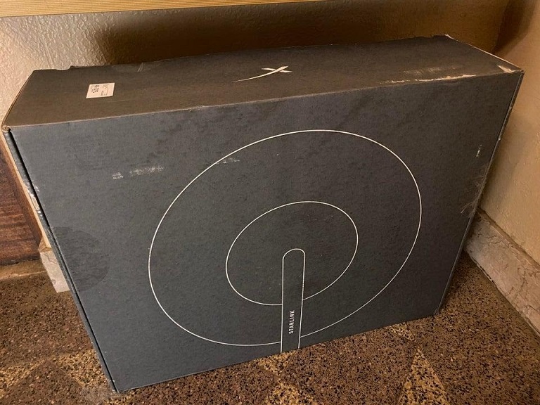
The terminal kit is supplied in a cardboard box measuring approximately 60 by 60 cm and weighing 9..9.5 kg.
In the photo there are boxes supplied at the stage of closed beta testing
At the stage of public beta testing, the delivery began in other boxes:
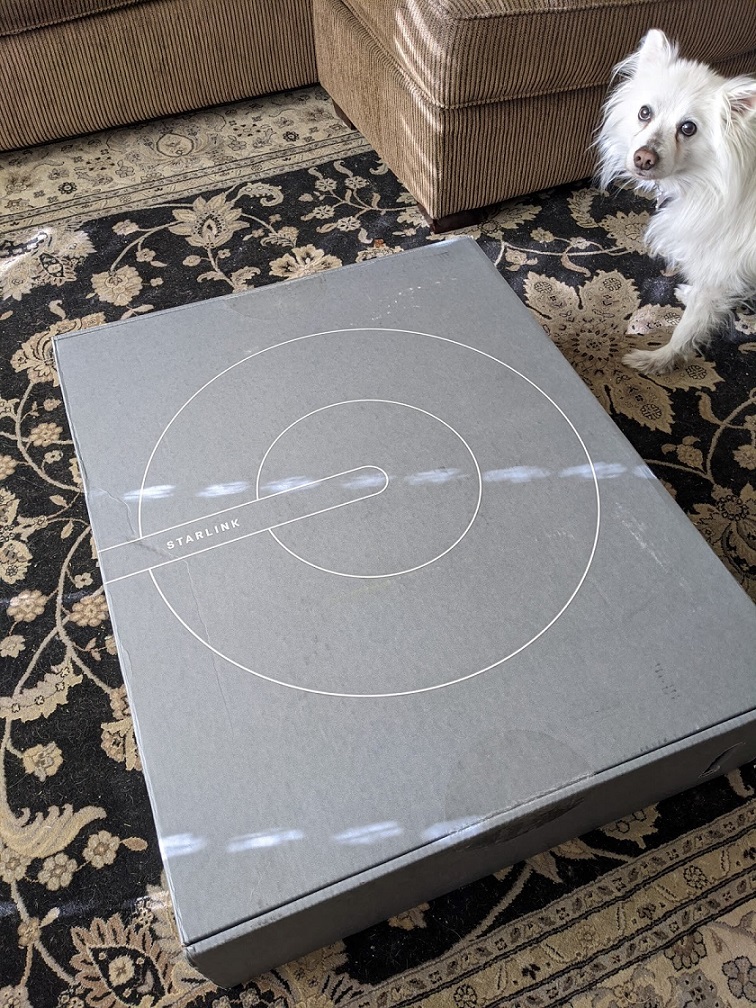
Inside view

Despite Elon Musk's famous tweet about Plug and Play:
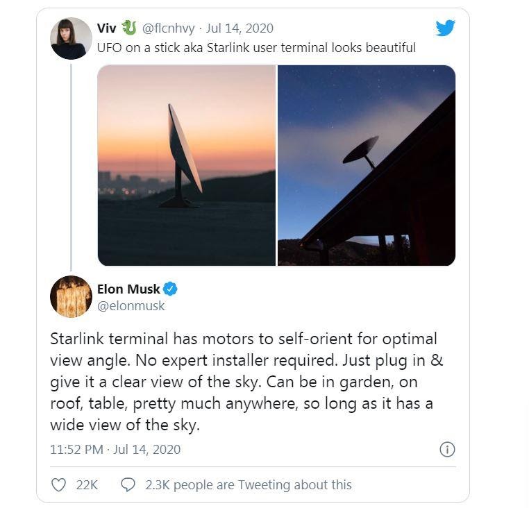
- this is very far from the truth. Before you “plug” the power supply cable into the outlet and start “play”, you will have to do an interesting event - the installation of the antenna.
The simplest and most typical solution is installation on a flat surface - a lawn:
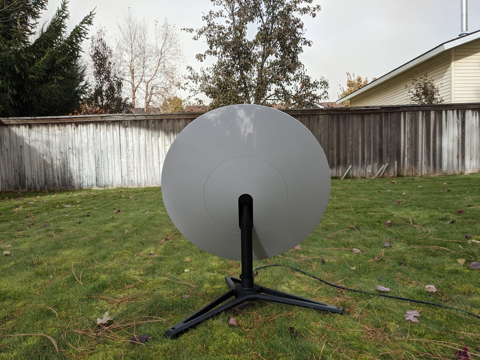
or a view from afar
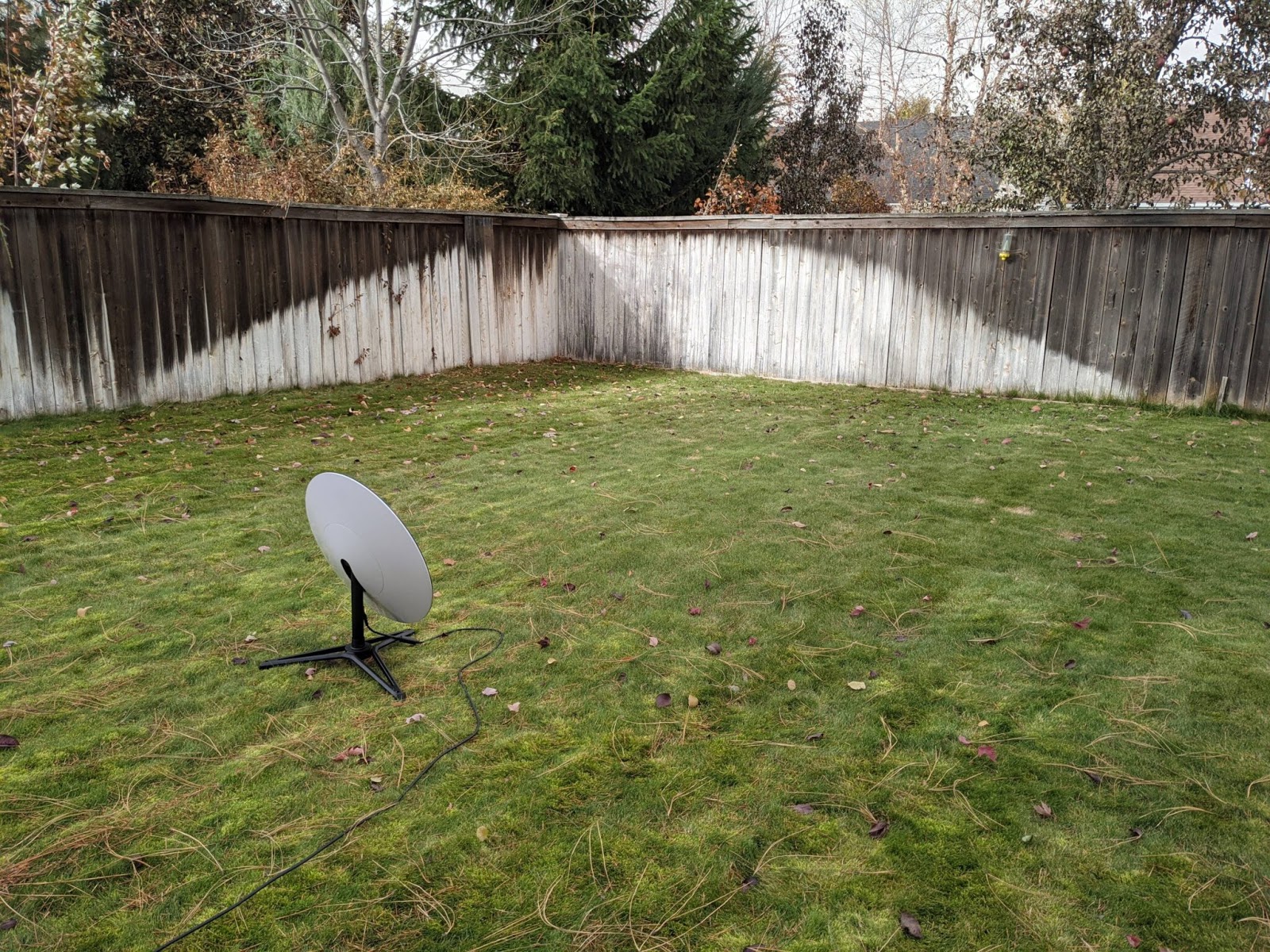
It is clear that the size of the support is too small for a strong wind and it will be necessary to roll the tripod-base with weights or screw it with screws / dowels to another solid surface.
A wire snaking on the grass, to put it mildly, is not the best solution if the Subscriber sometimes mows the grass with a lawn mower. Then the solution is roof mounting (also a typical solution). However, there is no 100% certainty that Generation Z, accustomed to iPhones, will cope with such an installation so easily when it will be necessary to drag and fasten such a structure onto the roof ridge:
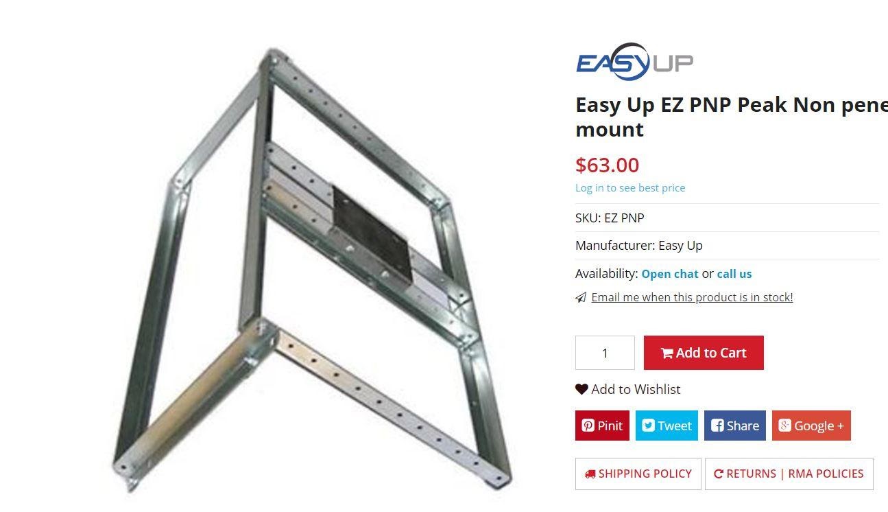
Figure: Easy Up EZ PNP Peak - Non-intrusive Starlink Antenna Mount on the Roof
The most difficult thing during installation is not to damage the waterproofing on the roof and secure it in the place where the cable gets into the house.
In general, according to the author, at least 50% of potential subscribers will decide to use the services of a professional installer or builder in order to save their time and money on future home renovations.
There is nothing to say about the internal structure of the antenna, because it is a corporate secret of SpaceX (at least until some terminal is stolen and uncovered by secret admirers of SpaceX engineers talent).
Most likely, there will be such chips / microcircuits inside (photo taken from C-Com, another manufacturer of flat phased array antennas):

Figure: Modules 4 by 4 elements RX for receiving, TX for transmitting. Canadian coin.
The most unexpected aspect of the antenna design is the presence of an electric drive. Judging by the design, the antenna will rotate in the horizontal plane 360 ° and deflect 50-60 degrees in the vertical plane. This decision (the introduction of an electric drive into the structure) is very controversial, since any rotating assembly is the cause of possible failures, especially taking into account the most diverse climatic conditions, when the antenna can be covered with an ice crust, dust, sand, etc. can get into the slots.
I believe that the introduction of the electric drive into the structure was made in order to avoid the need to work at small elevation angles - the inclination of the antenna towards the "working" satellite at the given moment increases the effective antenna area (see the formula for its calculation below) and, accordingly, the transmission rate and receiving information.
Antenna effective area = sin (elevation) * Geometric area.
That is, at an elevation angle of 25 °, the effective antenna area is only 42% of its geometric area. When turned on, the terminal antenna is oriented to the north, since there is the maximum "density" of satellites above the 53rd parallel. In this case, the angle of inclination of the antenna is large enough and allows you to have an almost right angle between the direction to the satellite and the plane of the antenna. When tested in the more southern regions of the United States, and even more so at the equator, the density of the satellite on the sides of the horizon will be approximately the same and the antenna will most likely look to the zenith.
Theoretically, the electric drive could, working constantly, deflect the antenna towards the nearest "optimal for operation" satellite, however, this imposes certain requirements on the speed of the drive and its resource. For areas below the 30th parallel, the satellites on the 50th parallel are no longer visible and the terminal tilt angle to the north will be less or not at all, although the density of the satellite is higher the further we are from the equator. In the equatorial area, the antenna will be directed almost horizontally to the ground and the "density" of satellites in the terminal's field of view is minimal.
Building a phased array terminal is not a complex technical challenge, but technology is more of a challenge. The fact is that modern subscriber terminals for communication with geostationary satellites with a parabolic antenna cost about $ 250, and according to the model adopted in the USA, they are not sold to the subscriber, but are provided to him for 2-3 years as part of the service. At the beginning of the Starlink project, Elon Musk pointed out that $ 300 is the target cost of the terminal. At the same time, modern phased array antennas from other manufacturers, for example Kymeta, now cost between $ 20-25 thousand. Therefore, SpaceX technologists have a very difficult task - to reduce the cost of the subscriber terminal to at least $ 1000, so that the business case converges in the near future. time. Note,that the announced price of $ 499 in November has a very weak connection with its current cost. Elon Musk himself fully confirmed this in his tweet dated November 3, 2020:
"Lowering Starlink terminal cost, which may sound rather pedestrian, is actually our most difficult technical challenge"

Previous materials:
- Everything about the Starlink Satellite Internet project. Part 1. Birth of the project
- Everything about the Starlink Satellite Internet project. Part 2. Starlink Network
- Everything about the Starlink Satellite Internet project. Part 3. Ground complex