The article dedicated to him at that time received a wide response among the audience, interested in "home automation" and simply not indifferent; and in this material we want to update the information about our product, tell how it has evolved during this time and what path we have traveled. But first things first. We hope you find it interesting, let's get started!
Circuit design
The thermostat is still a sandwich of three components: the bottom “power” board, the “smart” top board, and the touch-monitor (old friend - Nextion 2.4). In the future, we want to replace the monitor: we are working to create a similar display module, but with a capacitive touchscreen. This modernization will not affect the final cost: it will not increase it, but, unfortunately, production costs will not be reduced either. Users will benefit - the perspective display is more “responsive” compared to the resistive Nextion.
We also developed a non-screen version of the thermostat. The only difference is in the total cost and the possibility of hidden installation in a socket box.
All this allows us to install our thermostat instead of most third-party thermostats that use an analog sensor of the presented rating (more on that below).
The power section is unchanged, everything is in its place:
AC-DC 5V 700mA power supply, TE Connectivity relay (RT314005) 16A


But the thermostat's “brain”, both the hardware and its software, has undergone a much more thorough revision.

1 - minor change: the built-in ds18b20 temperature sensor was abandoned, the "space" for it remained, if necessary, the installation of diy should not be difficult;
2 - connector for Nextion monitor.
3 - connector for the future monitor (not installed in the image) - DIY fans will be able to use it to the fullest;
4 - seat for the radio module ss2530 (e18);
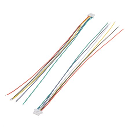
5 - connector for connecting the programming wire (in the image below).
With its help, the owner can change the software for any other compatible with the platform. Earlier versions provided only a "place" for soldering, but now it will not be difficult to reflash the device.
Watchdog (hardware) - for maximum reliability will restart the device if “something went wrong”. The previous jumper - a jumper to activate it - was replaced by an analog control key and a button.
In order to optimize space, the ESP8266 module has been moved to the bottom side of the board. The nRF24L radio module has been replaced with a cc2530 (e18) module, which will allow the thermostat to be used in ZigBee networks in the future.
The previously applied mechanism for connecting the upper and lower tiers into a single whole (image 1), unfortunately, showed itself not from the best side - its unacceptably low resource for these very connections - disconnections - was noted. We replaced it with a more reliable one (image 2).

Image 1

Image 2
Software component
We have added an experimental feature to the firmware with “MQTT” support in the form of native support for the Apple HomeKit protocol. In the future, we plan to receive an MFI certificate and provide full support for Apple HomeKit.
Experienced HomeKit firmware makes integrating the thermostat into Apple's smart home ecosystem transparent and easy. You can configure and control the device using both its touch screen or web interface, and the native Apple application “Home”.
In the proprietary version of MQTT, communication with the rest of the world of “smart things” is carried out using the MQTT protocol through an MQTT broker, which opens up opportunities for integration with almost any systems on the market (MajorDoMo !, Home Assistant, etc.). In general, it is characterized by more flexible settings, allows you to customize "scripts".
The user can switch between these two versions at any time using the web interface.
Let's describe all the possibilities in more detail
The mechanics of interaction and interface design for the touchscreen monitor built into the thermostat have been redesigned. The basis was the experience of operating users, their requests. Including the comments under the article (thanks again!) And suggestions for improving the interface in our Telegram group helped a lot . The website got it too .
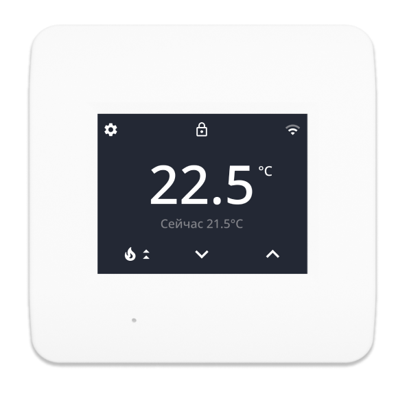
This is how the main page looked in the old version:

Now it looks like this:
Let's review all the thermostat settings.

Old interface
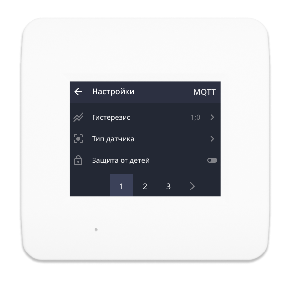

New interface
You can:
- ( +- 5.0 0.5);
- ( ds18b20 );
- ( );
- Over-the-air (« »);
- “ ” : , ;
- — .
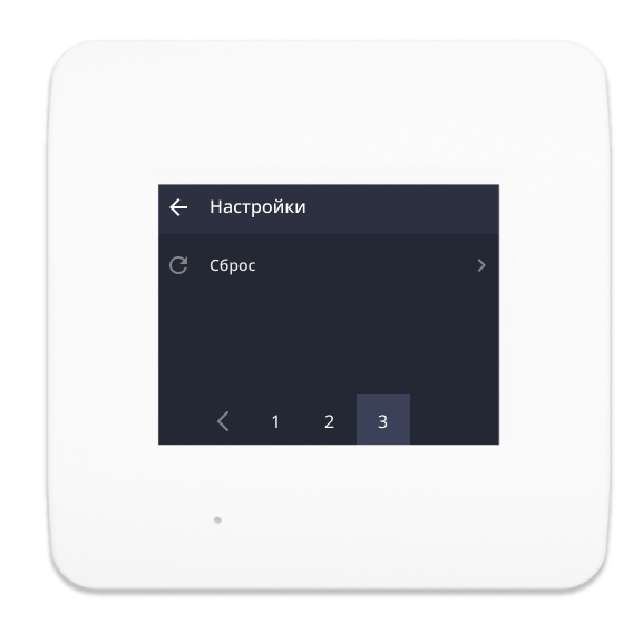
In addition, you can customize temperature thresholds: minimum and maximum allowable values. The range is currently adjustable from 7 to 75 degrees, but in the future we will increase the upper threshold to 90 degrees. This will allow the thermostat to be used to control the heating boiler. These values are set only at the time of initial configuration. If you need to change them, you will need to reset the device and re-configure the parameters.

We are constantly expanding the list of supported analog temperature sensors, and at the moment it looks like this:
- 3.3 kΩ,
- 5 kOhm,
- 6.8 kΩ
- 10 kOhm,
- 12 kOhm,
- 14.8 kΩ
- 15 kOhm,
- 20 kOhm,
- 33 kOhm,
- 47 kOhm.
Of course, support for the ds18b20 digital sensor is preserved (it is selected by default).


The web page allows you to make all the above settings. Besides:
- connect to an MQTT broker;
- see the description of topics for device control;
- update the device from the Server, or download the firmware file manually;
- change the operating mode from MQTT to HomeKit and back;
- reconnect the device to a different Wi-Fi network.

Preparation for work
The data for connecting to the ESP access point is encoded in the qr-code displayed on the screen when first turned on (on the version with the screen). Just “scan” it with your smartphone and accept the offer to connect to the AP of the thermostat. In the version without a screen, you will need to manually connect to the “Lytko-xxxx” access point.

After connecting to the network and the initial configuration on your smartphone, the device is ready for use. Everything.
Feedback
In addition to suggestions for improving the interface of the thermostat, we also receive ideas for expanding the functionality of the device: what if we install the same thermostat to control the boiler? At the request of one of the members of our Telegram group, we added boiler support to the firmware by increasing the upper temperature threshold to which the controller allows heating the connected device.
At the first start, you will need to set the maximum temperature to the required level at the time of the initial configuration.
A colleague connected the thermostat to the hot water boiler and wrote an article about it .
Achievements
Our thermostat is now on the TV, or rather, in the lens. A video about our product was released on the YouTube channel Electronics in the lens . The Lytko team is grateful to the author for a thorough review of the device and a capacious demonstration of the functionality. We took into account the criticism expressed by the author and are working on correcting all the shortcomings. The review presents two models: conventional underfloor heating * and dry contact. * although the thermostat of this version can also be used in conjunction with a boiler, some of our users have been able to configure it to control valves on radiators. So far, only through a wired sensor, but we are also developing options for obtaining temperature from the outside: using a BLE sensor, a ZigBee sensor or an external MQTT sensor.
PS: we are not satisfied with what has already been achieved and have prepared a new version of the device with ESP32 on board. The tests will begin soon.

