spacecraft are specially designed for group launch with two stacks of 30 satellites each under the fairing of a Falcon 9 rocket and have dimensions: length - 3.2 m, width - 1.6 m, height - 0.2 m (size estimate made from the photo below).

The photo shows the laying of Starlink satellites under the fairing of a Falcon 9 rocket. Parabolic antennas for a feeder link with Ka-band gateways are circled in red.

Starlink satellites at the time of separation from the second stage of the Falcon 9 rocket. Parabolic antennas for a feeder communication line with Ka-band gateways are circled in blue.
Here you can watch a video of the separation of satellites from the FALKON rocket
After putting a group of satellites into a reference orbit (as a rule, it is 280 km), the satellites open solar batteries, establish contact with the ground control center and carry out a check for operability and absence of damage when separating from the rocket, then they activate electric rocket engines (ERE) on krypton and begin movement to the working orbit, which takes 2-3 months.
At launch, solar panels are folded like an accordion and have 12 segments, where the long side of each segment is equal to the satellite's width (3.2 m)

We can estimate the dimensions of each segment at 3 mx 0.8 m. Thus, the total solar array area is 12 x 3 x 0.8 = 28.8 m2.
Due to losses between solar cells and at the edges (fill factor 0.9 ), this value can be rounded up to 26 m2.
Let us take the solar radiation flux density as 1300 W / m2, the panel efficiency at 18%, and we get approximately 6 kW of maximum (peak) electrical power. (For comparison, satellites "Express" on the platform "Express -1000" weighing 1450 kg have a solar battery capacity of about 3 kW, but perhaps this is an average value).
The actual power depends on the position of the solar panels relative to the Sun: the optimal incidence of rays on the panel is at a right angle.
To move a satellite from a reference orbit of 280 km to a working orbit of 550 km and keep it on it, plasma thrusters or ERE are used. If we start from EJE for small satellites such as Russian SPD-100 or foreign BHT-1500, then their power consumption is approximately 1.5 kW, and thrust is 100 mN, with a specific impulse of 1700-1800 seconds. The EJE looks something like this (see figure below) and has dimensions of approximately 20x20x15 cm.

EJEs have a supply of krypton of approximately 5-10 kg, which is filled into high-pressure balloons. This margin will make it possible to lift the satellite into a circular orbit of 550 km, keep the satellite in it for five years, and then change the orbit from circular to elliptical, changing the perigee from 550 km to, say, 250 km, where, due to the deceleration of the rest of the atmosphere, the satellite is sufficient quickly decelerate and burn.
The main payload of the Starlink satellite is 2 antenna complexes for communication with gateway stations (gateways) and subscriber terminals.
Antenna complex for communication with gateways (or feeder line) are parabolic antennas pointed during flight to the point on the Earth where the gateway is located. The feeder line operates in the Ka-band (18/30 MHz).

As follows from the table, the satellite has 2100 MHz at its disposal in the direction from the gateway station to the satellite and 1300 MHz in the opposite direction. Using both polarization options (left and right in the case of circular), this allows a maximum of 4200 MHz to be used for traffic transmission from the gateway to the satellite and 2600 MHz in the opposite direction.
Also on board are 4 flat square antennas with a phased array - three for transmitting information from the satellite to the subscriber terminal and one for receiving a signal from the terminal.

Figure: View of four Ku-band phased array square antennas before and after coating to reduce visibility from the ground.
Communication between the subscriber terminal and the satellite is carried out in the Ku-band, while 2000 MHz can be used for transmission from satellite to subscriber, and only 500 MHz from subscriber to satellite. Given the two polarizations for traffic transmission, the satellite has 4000 MHz down and 1000 MHz receive.
Also on board there is a set of equipment for the command radio link and telemetry transmission, using 150 MHz, respectively, in the Ka and Ku bands.
The Starlink satellite is a repeater and does not process information: on board it only changes the frequency of the received signal and its amplification. Also, satellites of the first generation do not have inter-satellite communication (ISL - Inter Satellite Link) and can only receive and transmit information to the Earth. As a TT&C station (command, control, receiving telemetry) 4 earth stations are declared, including the Brustner teleport located in Washington state. The Starlink satellite is in the visibility zone of the TT&C station for no more than five minutes, while the amount of data collected from the constellation was about 5 TB per day in June 2020, that is, at least 10 GB from one satellite per day.
Each Starlink satellite has about 70 separate Linux processors and about 10 microcontrollers on board.
Being in an orbit of 550 km, the satellite can cover with its signal a spot on the Earth with a radius of 950 km (that is, with a diameter of approximately 1900 km), provided that the elevation angle for the subscriber terminal is not less than 25 °. Note that the effective operation of flat phased array antennas is possible at an elevation angle of 40 ° or more.

Figure: The radius of the satellite's visibility zone at an angle of 25 degrees, depending on its height.
| Orbit "a", km | 540 | 560 | 570 |
| Max deflection angle α (in degrees) | 56.7 | 56.4 | 56.3 |
| Coverage area "r", km | 926.8 | 954.6 | 968.4 |
It is easy to calculate how many satellites are needed to provide 100% coverage of the Earth between the north and south 50 parallels, provided that the satellite signal covers the entire field of view of the satellite on Earth. The surface area of the Earth between the north and south 50 parallels is 300.4 million square meters. km (the entire surface of the globe is 510 million square kilometers). Since we need 100% coverage with no gaps, the zone circles will overlap and 100% coverage is ensured if we only use the “squares” in the light zone circle. The side of such a square is L = D / √2
Or, in our case, L = 1356 km, and the area covered by the square is 1.84 million square kilometers. Thus, only 164 satellites will provide 100% coverage of the Earth between 50 north and south parallels?

So why is Space X 1584 AES?
And here we must talk about such a parameter of any antenna system as the antenna directional pattern.

Antenna radiation pattern is a very important antenna parameter, and the characterizing criterion here is the angle at which the signal power is 2 times (and in DeciBels this corresponds to 3 dB) higher.

Antenna radiation pattern angle depends on its diameter (area), surface utilization factor (UUF) and signal frequency. In this case, the instrumentation is determined by the distribution of the field amplitude over the working surface of the antenna, power leakage beyond the edges of the antenna mirror and other losses. In addition to the main lobe of the radiation pattern, the antenna also has side lobes and a back lobe. These petals are secondary and take energy from the main petal of the DN. When designing antennas, the goal is to increase the ratio of the energy of the main lobe to the first (largest) side lobe.
The larger the diameter (area) of the antenna, the smaller the angle of the radiation pattern and the greater its gain (Cus).
So what are the StarLink antenna patterns? For a subscriber terminal in 2020, in documents filed with the FCC, Space X published the following table:

If we focus on the above-mentioned diameter of the beam spot on the ground at 45 km, then this corresponds to the angle of the satellite beam pattern (from space to Earth) at 4.5 degrees (when deviating from the nadir line, the angle can apparently change from 3 to 5 degrees, the farther from the nadir line, the greater the angle), which correlates well with the parameters of a flat antenna of this size.
SpaceX's initial filing from 2016 indicated that the beam would be 45 kilometers in diameter. (page 80 of Appendix A of the Technical Part to SpaceX's FCC filing dated November 15, 2016).
To assess and visualize the StarLink coverage area, assume that the antenna beam angle on the satellite changes from 3.5 degrees (nadir) to 5.5 degrees at the edge of the area. Calculations of the diameter of the coverage area show that the beam diameter corresponding to a beam angle of 3.5 degrees directly below the satellite will be 34 km. As the beam deviates away from the nadir line, the angle of the radiation pattern increases: according to SpaceX data in the table above, it will be 5.5 degrees for the edge of the zone, while the diameter of the coverage area of one beam on Earth increases and reaches about 210 km at the periphery of the visibility zone AES with an inclination angle of 25 degrees. Based on this geometry and the characteristics of the StarLink satellite antennas, the projection of its rays onto the Earth will look like this:

One satellite in this way can theoretically have up to 300 such beams in its coverage area. Here is a projection (view from the satellite side) of the field of view, in which the subscriber terminals see the satellite at an elevation angle of 25 degrees.
<img src = "
 " align = "center">
How many beams will be organized on the StarLink satellite cannot be directly understood from the Space X documents, however, we can easily determine the maximum number of beams that can be operated in the line of sight of one StaRLink satellite using the fact that in the Ku band it is impossible to use more Megahertz to transmit information from the satellite to the subscriber terminal than we have in the Ka band for transmission over the feeder line from the gateway to the satellite - that is, 4200 Megahertz in the case of using both polarizations.
Here we make the following assumption that the StarLink satellite belongs to the "bent pipe" type, that is, without information processing on board (that is, without demodulating the radio signal into IP packets and forwarding them), that is, since all modern communication satellites of much larger sizes work and service life So far, there is no evidence that the first generation StarLink satellite may be processing data.
As can be seen from the table of parameters of the subscriber terminal (see section StarLink Subscriber Terminal) that the satellite channel from the satellite to the subscriber terminal has a maximum width of 240 MHz in the downward direction and 60 Megahertz in the upward direction to the satellite. In such a configuration, which is optimal from the point of view of the efficiency of using the frequency resource in the coverage area of one satellite, no more than 16 beams will be able to operate, which fully use the available 4000 MHz frequency resource in the Ku band (taking into account the guard intervals and frequencies for the command radio link and telemetry transmission) at using both polarizations when transmitting from the satellite to the subscriber terminal.

Note that a parabolic antenna is used for the Ka-band feeder beam, which provides "lifting" of Internet traffic on board the satellite. In order to ensure maximum throughput with a fixed available Ka-band frequency band, it is necessary to ensure the maximum signal-to-noise ratio by increasing the signal power from the satellite, and for this it is necessary to minimize the coverage area on Earth as much as possible - in modern systems, working with HTS satellites, its diameter is about 100 kilometers. Considering that StarLink satellites are at a much lower altitude than geostationary satellites, the diameter of the feeder beam zone can be even smaller. An additional advantage of the Ka-band narrow spot is that the satellite signal does not interfere with other Ka-band systems on Earth.
The control of the deviation of the beam from the nadir in the coverage area will be a phased antenna of the satellite, which can deflect the beam in any direction (steerable beam) and even change its shape (shapeable) according to the Space X application to the FCC.
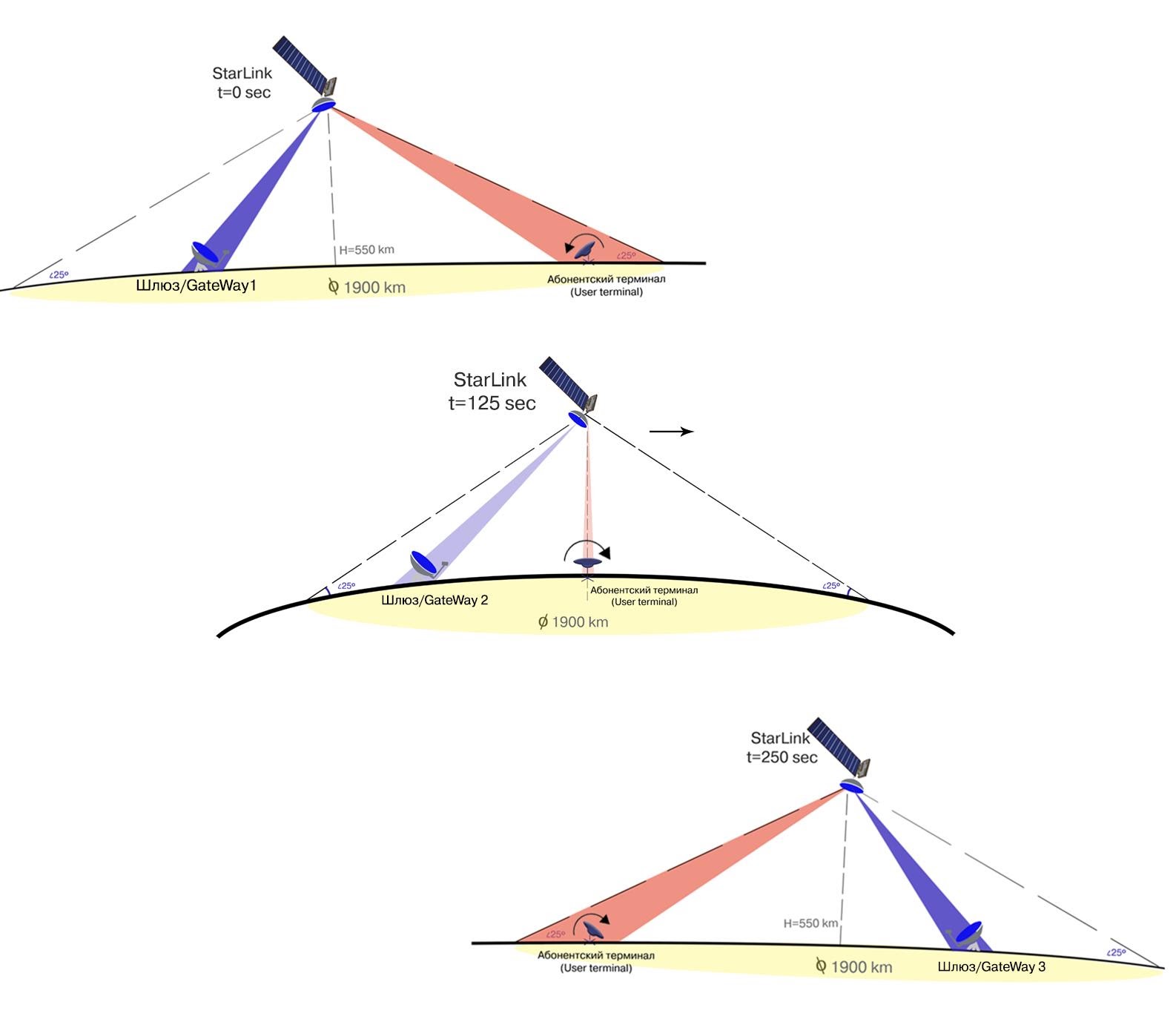
At an altitude of 550 km, the satellite moves at such a speed that the time of its flight in the visibility zone of the Subscriber Terminal is 4.1 minutes, or approximately 250 seconds. If the StarLink system implements the ideology of the maximum session time of the satellite with a group of terminals located in the same area and the minimum number of handover of the terminal to different ones, then this is illustrated by the following figure, in which the satellite controls its beam by installing it on one group of terminals in one geographic area.

Another option assumes that the beam on the satellite is fixed in some one position (tilt angle) to the Earth and the task of the subscriber terminal's antenna is to "get" into this beam. This option requires a very large number of satellites, taking into account that the antenna directional pattern of the subscriber terminal is also small.
The small number of beams on board the satellite makes it difficult for Space X to cover 100% of the territory and gives an answer to the question of why Space X is forced to launch so many satellites. Even more interesting, these same calculations provide the answer why Space X is forced to reduce the minimum elevation angle from 40 degrees to 25 degrees, despite the fact that this dramatically reduces the efficiency of its phase-array antenna.
The diameter of the AES visibility zone with an elevation angle of up to 25 degrees at an AES height of 550 km is approximately 1900 km, the area of this zone is 2 835 294 sq. Km
The table below calculates the number of satellite beams required to fully cover the area visible from the satellite on the Earth's surface in within an elevation angle greater than 25 degrees. The subscriber terminal antenna diameter is taken as 48 cm.
| Elevation angle, degrees | Beam zone diameter, km | Beam area, km2 | Number of beams for full coverage of the area | Effective antenna area, m2 |
| 80 | 40 | 1,257 | 2 256 | 0.178 |
| 70 | 50 | 1964 | 1,444 | 0.170 |
| 60 | 60 | 2827 | 1 003 | 0.157 |
| 50 | 80 | 5027 | 564 | 0.138 |
| 40 | 130 | 13,273 | 214 | 0.116 |
| thirty | 210 | 34636 | 82 | 0.090 |
Obviously, from the point of view of covering the maximum area, it is more efficient to work with beams directed from the satellite not to the nadir (sub-satellite point), but to the periphery of the visibility zone, despite the fact that there the effective antenna area (and hence its throughput) sharply decreases ...
It is also now possible to estimate the number of beams, and hence the number of satellites required for 100% coverage of any parallel, for example, the 50th parallel of north latitude (its length is 25,740 km, where closed beta testing is currently
taking place . At an elevation angle of slightly less than 40 degrees and the beam diameter of 160 km, the guaranteed width of the coverage area (the width is equal to the side of the square inscribed in the circle of the beam) is 113.5 km and corresponds to 227 satellites visible from the 50th parallel along its entire length around the Earth.
The area of the earth's surface between the 53rd parallels is 300.4 million km. If we take the effective coverage area of 1 beam as 113.5 by 113.5 = 12876 sq. Km, then the required number of beams will be 23330, and if there are 16 beams on one satellite, we need at least 1458 satellites for full coverage, which is very close to 1584 announced by Space X for the first phase of StarLink deployment.
It also becomes clear the reason for the appearance of the drive mechanism in the StarLink terminal is connected precisely with the need to rotate the antenna towards the satellite in order to provide a more or less decent angle between the phased plane and the direction to the satellite at small elevation angles of the terminal (ideally 90 degrees).
The overall coordination and control of the entire network of satellites, gateways and subscriber terminals is carried out by the Network Operations Center - this is the most unknown, invisible and undisclosed part of the Starlink system.
The lifespan of the Starlink satellite in an orbit of 550 km is about 5 years, after which the supply of the working medium of krypton ends, and the satellite either on command lowers its orbit to dense layers of the atmosphere, or, in case of loss of communication with the Earth, gradually decreases, decelerated by the remnants of the atmosphere. and burns up (more on this will be written in the section on space debris).
Starlink satellites are being produced for the first time in the world in almost large-scale production mode. According to SpaceX, its production capacity is capable of producing up to 120 Starlink satellites per month. Note that the average production time for a communication satellite for a geostationary orbit is now 2-3 years.
Undoubtedly, such a rate of production greatly reduces the test and inspection cycle, and we also note that to save money in the satellite, cheaper components and components are used, in particular, expensive xenon is replaced by a much cheaper krypton as the working fluid of the EP.
Thus, a decrease in the requirements for components and the ground test cycle is reflected in both the resource and the reliability of satellites, the design of which is being finalized based on the results of tests in space.
On September 13, 2020) the reliability of Starlink satellites was characterized by the following table:
| A type | Total launched | Deorbited by command from Earth | Uncontrolled deorbiting | Do not maneuver (probably out of order) | % remaining in orbit |
| Version 0 (AES Tintin) | 2 (2018) | 2 | 0 | 0 | 0% |
| Version 1ISZ type 0.9 | 60 (2019) | fourteen | 0 | eight | 63% |
| Version 2ISZ type 1.0 | 653 (from 2019 to nv) | 4 | 1 | eight | 98% |
On October 1, 2020, Space X published new information, introducing the concepts of "Dead" - loss of communication with the satellite, and "non-maneuverable" - failure of the remote control. This is what the state of the StarLink satellite constellation looked like on October 1.

Next, we will talk about the most complex and most important element of the Starlink network - the ground complex.