Today we will find out what else is included in the design of the carburetor besides the main dosing system and the idle system , which have already been considered.
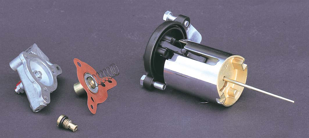
If there are no special requirements for mixture formation, the carburetor will work well with only the main metering system and an idle system in its design. However, their capabilities are not enough to simplify starting a cold engine, eliminate dips in the dynamics of speed gain when the throttle is suddenly opened, and maintain the best throttle response without losing maximum power. To eliminate these effects and further improve engine performance, a number of carburetor accessories are used, which will be discussed in this article.
Starting device
When the engine is cold and the ambient temperature is relatively low, part of the combustible mixture does not reach the combustion chamber, condensing and settling on the walls of the intake manifold. As a result, the mixture is depleted, which makes it difficult to ignite. Starting the engine becomes problematic, and operation is erratic and difficult to control until the engine is fully warmed up.
To facilitate the task of cold start, special starting devices are used - enrichers. They are designed for the required enrichment of the combustible mixture during cold start-up and warm-up. In other words, the concentrator prepares an additional amount of a combustible mixture, which is sufficient (when working with other carburetor systems) for starting and stable operation during the first time after starting.
Similar devices are found in all carburetor designs, with the exception of some specific models used on sport bikes, where the starting procedure is slightly different.
In the simplest case, the starting device is a kind of lever that allows the driver to forcibly lower the floats in the float chamber, thereby increasing the fuel level, which leads to an enrichment of the mixture. The principle of operation was determined by the name of the concentrator - float sinker. With this design, the mixture is enriched in all carburetor systems, and a return to normal operation is possible only after starting the engine (when part of the fuel is consumed and the level returns to normal).
The main advantage of the float sinker is its simplicity of design. The disadvantages include the dependence of the degree of mixture enrichment on the exposure time. Since the impact is carried out manually by the driver, the composition of the mixture will depend on his skill and experience. In addition, to work with the drowner, direct access to the carburetor is required, which is not always possible. For these reasons, float drowners are less and less common in modern carburetor designs. More advanced enrichment systems were developed with a fuel supply independent of other carburetor systems, including jets, valves and other regulating elements.
Consider the following enrichment design.
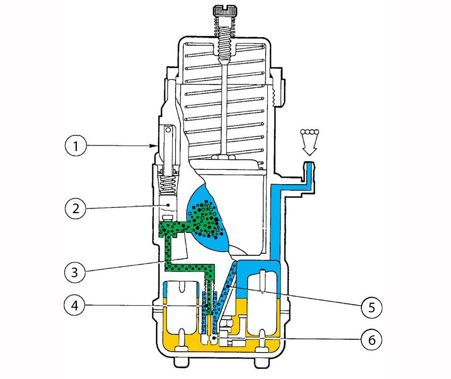
The design of the enricher of the Dellorto carburetor of the VHSB series: 1 - valve control lever; 2 - cylindrical valve; 3 - channel for supplying the mixture to the diffuser; 4 - emulsion tube; 5 - air channel; 6 - fuel jet
A miniature cylindrical valve 2 acts as a control element. The valve is controlled by the driver manually (directly or by means of a cable). The maximum enrichment is determined by the corresponding nozzle 7, regardless of the degree of valve opening and the version of its drive. The design of the fuel well of the enrichment unit and the location of the fuel jet are such that the work of the enrichment unit can be divided into two stages.
When the engine is shut off, the emulsion tube of the enrichment jet 5 is completely filled with fuel to the general level in the float chamber. Since the fuel level is the same, a weak vacuum at the moment of starting is sufficient for the required amount of fuel to flow out through the enrichment unit. At this stage the mixture is very rich, making it easy to start the engine.
After starting the engine, the emulsion tube quickly empties as the jet restricts the filling rate. The mixture starts to lean, but it is still rich enough for stable cold engine operation. After a while, determined by the degree of heating, the driver (or other control element) turns off the enrichment system.
The further development of starting devices was the introduction of automatic control systems.
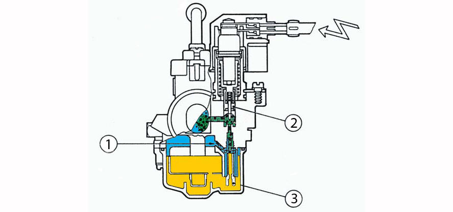
Automatic concentrator design: 1 - air channel; 2 - cylindrical valve with a conical needle; 3 - fuel jet combined with an emulsion tube
Their main difference is that they are able to automatically reduce the degree of mixture enrichment as the engine warms up. The most widespread are thermoelectric systems. A sectional view of a real control device is shown in the figure.

Thermoelectric control device for the enrichment unit: 1 - valve with a conical needle; 2 - returnable spring; 3 - thermosensitive element; 4 - heating element
At the heart of such a control device is the heating 4 and temperature-sensitive 3 elements. Inside the temperature-sensitive element is a substance that expands with increasing temperature. A heating element increases its temperature when a constant voltage is applied to it. The characteristics of these elements are selected in such a way as to match the warm-up and cool-down times of the engine.
On cold start, valve 1 is initially open. After starting the engine, voltage is applied to the control device, the heating element increases its temperature in proportion to the degree of engine warming up, the substance inside the temperature sensitive element also expands in proportion and it begins to gradually close the valve. By the time the engine is fully warmed up, the valve will completely shut off the fuel supply. After stopping the motor and as it cools down, the temperature-sensitive substance will decrease in volume, under the action of the return spring 2, the valve will begin to open. Thus, the mixture is automatically enriched by the value required for the current temperature.
Accelerator pump
The accelerating pump is designed to compensate for the depletion of the mixture when the throttle is suddenly opened. Overestimation occurs due to a sharp decrease in rarefaction due to a sharp increase in the cross-sectional area of the diffuser. As a result, there is a dip in the engine speed set.
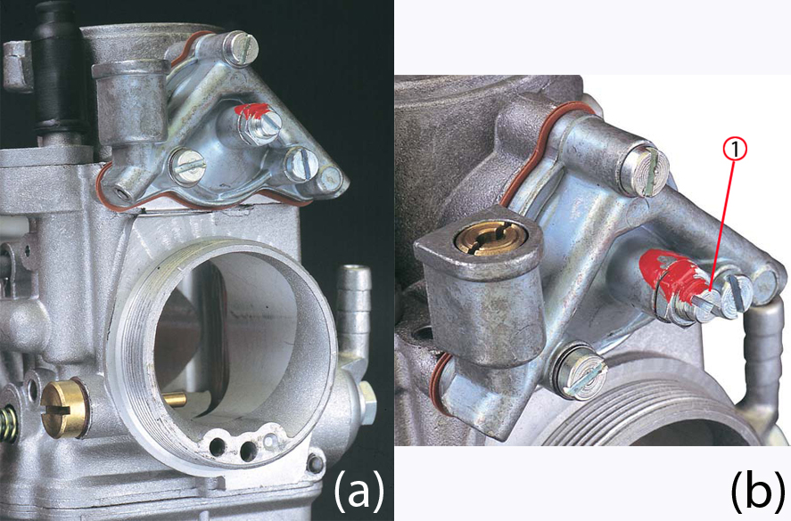
General view of the diaphragm accelerating pump. The number 1 marks the diaphragm travel adjustment screw.To
eliminate the dip when gaining speed, an accelerating pump is introduced into the carburetor design, which injects a strictly defined amount of fuel directly into the carburetor diffuser when the throttle is suddenly opened.
Accelerator pumps are of two types: plunger and diaphragm. The booster pump is driven by the throttle valve directly or via a lever system. For example, on Dellorto PHF and PHM series carburetors, the diaphragm accelerator pump is driven by a lever 3 sliding on an inclined plane in a special groove 4 of the throttle valve. When the throttle valve rises, the lever slides along the slope of the slot, flexes and presses on the diaphragm.
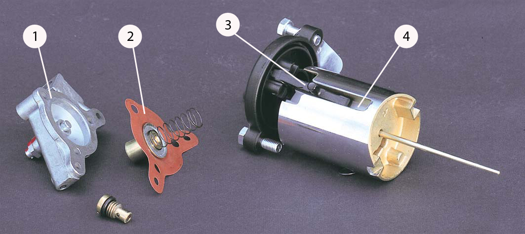
Pump diaphragm drive system: 1 - accelerator pump body; 2 - diaphragm; 3 - lever; 4 - groove with an inclined plane
The engine may need enrichment at the initial moment of a sharp throttle rise, or less intense but more prolonged enrichment during the entire lift time. By changing the angle of inclination and the length of the inclined plane, it is possible to adjust the start of the injection moment and its duration. In another way, the amount of injected fuel can be adjusted with a screw that sets the stroke of the diaphragm. By turning the screw clockwise, the stroke of the diaphragm decreases, which leads to a decrease in the amount of injected fuel, counterclockwise rotation gives an increase.
With the other pump settings unchanged, the injection duration can be adjusted by the nozzle, through which fuel is supplied to the diffuser. A large jet gives a shorter injection time, a small one, respectively, longer. In this way, the pump flow can be adjusted to the specific requirements of the engine.
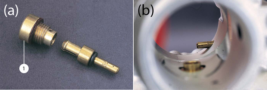
Accelerating pump jet: The jet in the body is fixed with a special screw 1, which is accessible from the outside of the carburetor, which makes it easy to replace during the adjustment process.
Econostat
For better throttle response, the carburetor of a two-stroke engine must maintain a relatively lean mixture at low to medium throttle rises. As mentioned earlier, the main jet not only determines the composition of the mixture at full throttle, it also has a significant effect on the composition during partial rises, along with the metering needle.
If you use a reduced flow main jet for best performance at medium throttle ramps, the mixture may become too lean for maximum power. Conversely, installing a higher flow orifice can result in a too rich mixture at medium gradients, which will impair engine throttle response.
Econostat can eliminate this problem. It supplies fuel directly to the diffuser only when the air speed is high - at maximum power. This compensates for the insufficient flow capacity of the main fuel jet.
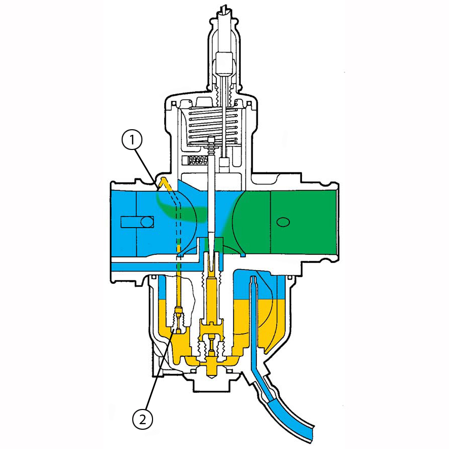
Econostat operation scheme: 1 - fuel supply hole; 2 - fuel jet The
fuel jet of the econostat, like all others, is located in the float chamber. The fuel supply to the diffuser is located at the top of the main air duct. This location of the hole is due to the need to supply fuel through it only when there is a strong discharge in the diffuser, when the throttle valve is fully open.
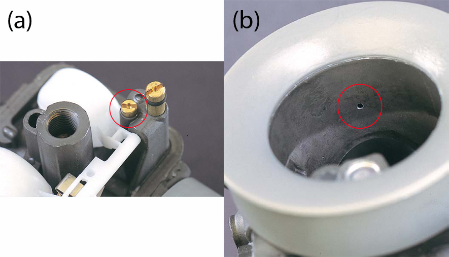
Econostat elements. The color highlighted fuel jet (a), fuel inlet (b).
The presence of an econostat in the design of the carburetor somewhat complicates its adjustment in the maximum power mode, since the econostat and the main dosing system work in parallel at this moment and the resulting composition of the mixture depends on their joint work. However, a high-quality tuning allows you to maintain maximum power without losing in engine throttle response.
To be continued...