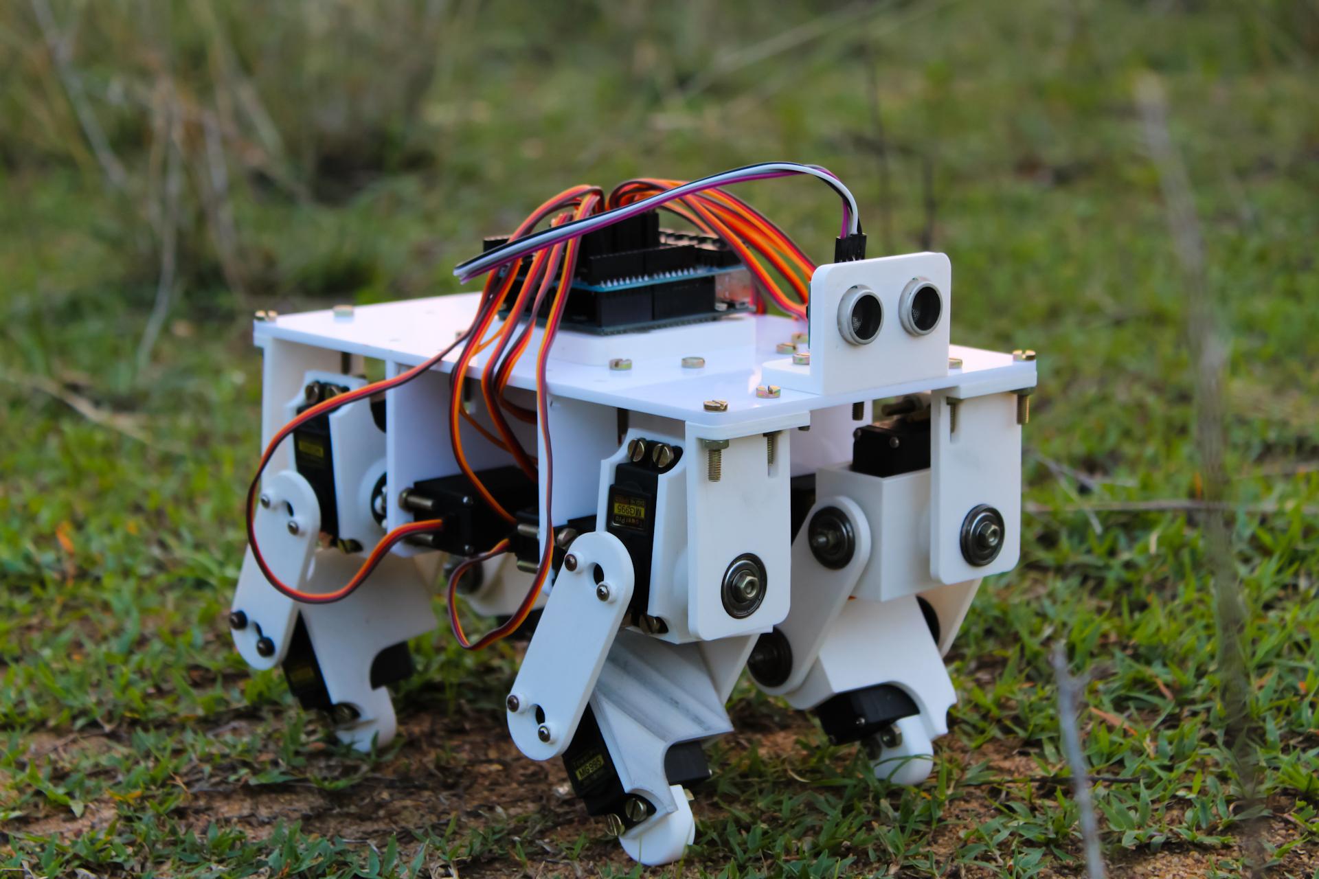
I am actively interested in robots, and recently made a bipedal robot powered by Arduino. After that, I wanted to make a four-legged robot that mimics animals such as dogs or cats. In this article, I will talk about designing and assembling a four-legged robot.
The main goal of this project was to make the system reliable enough so that during the experiment with different gaits I would not have to worry about possible equipment failures. This allowed me to push the robot to the limit by giving it complex gaits and different movements. An additional goal was to make a relatively inexpensive prototype using off-the-shelf components and 3D printing for rapid prototyping. Together, these two goals provide a solid basis for various experiments and the development of more specialized four-legged robots with more specific goals - navigation, obstacle avoidance, dynamic motion adaptation.
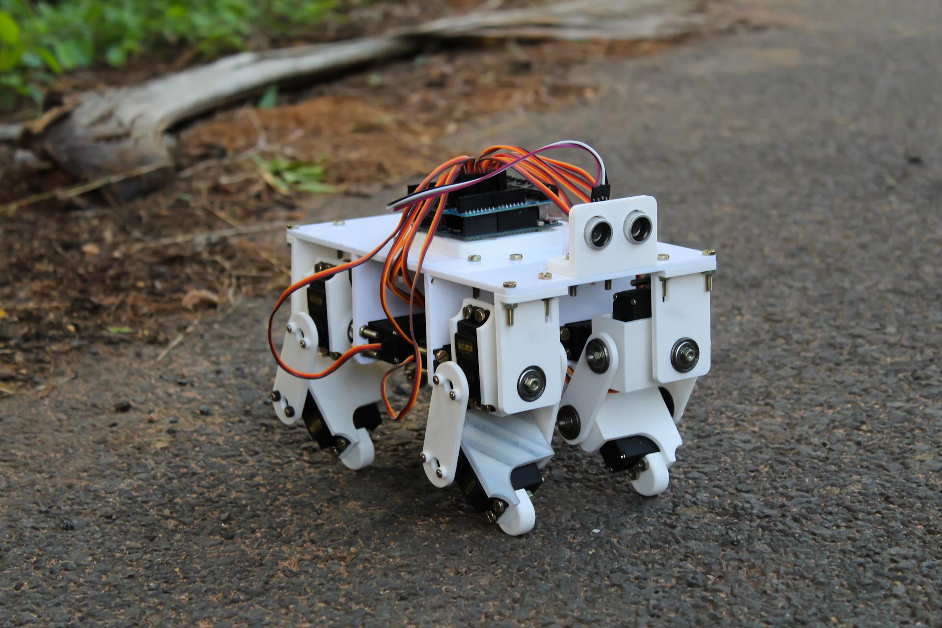
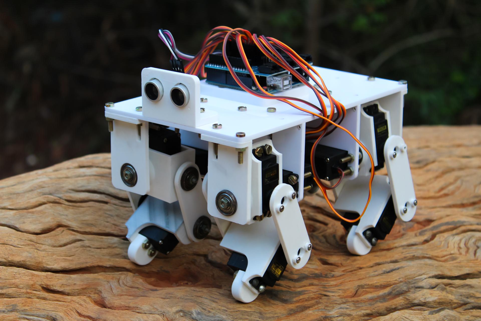
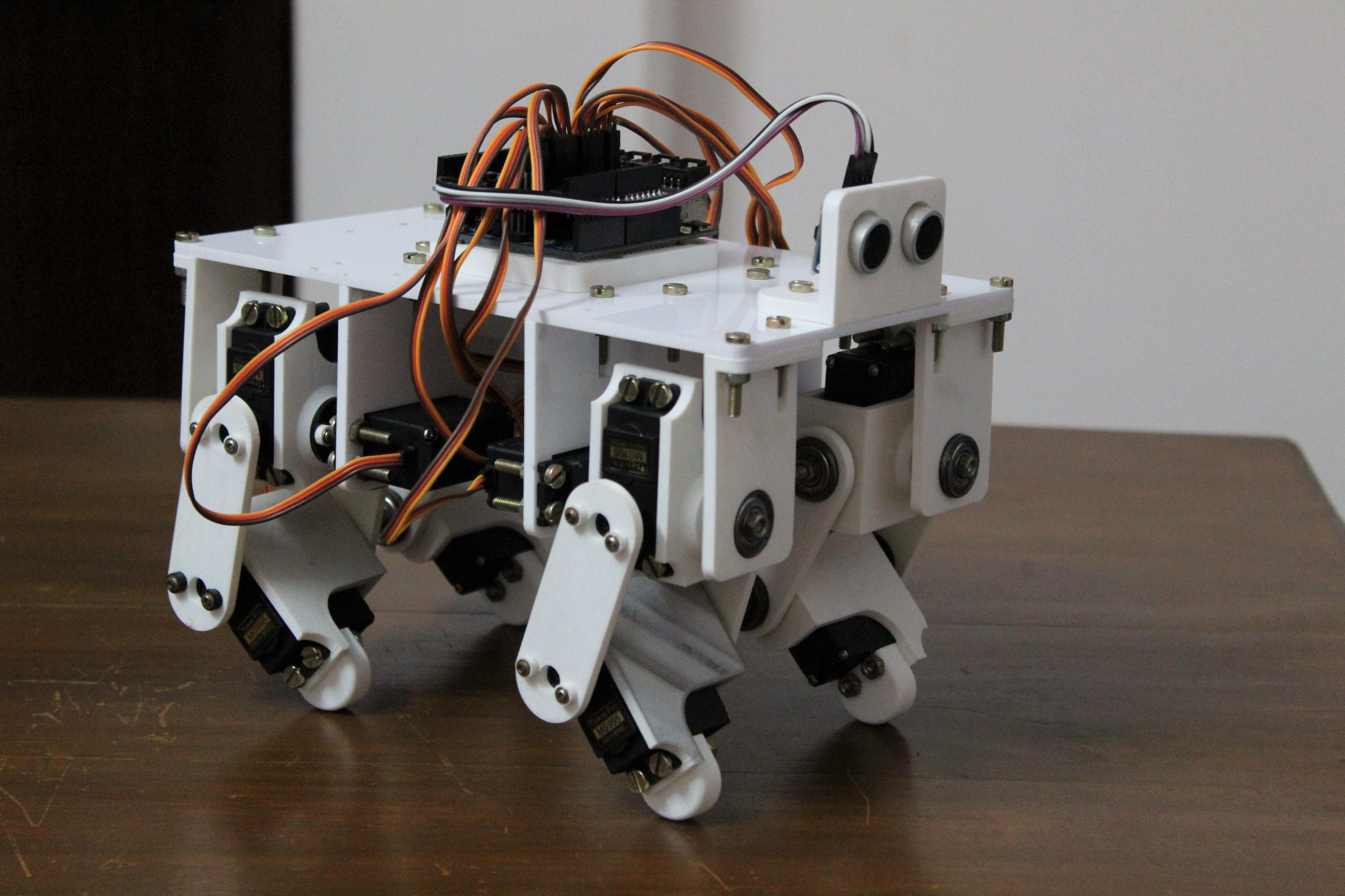
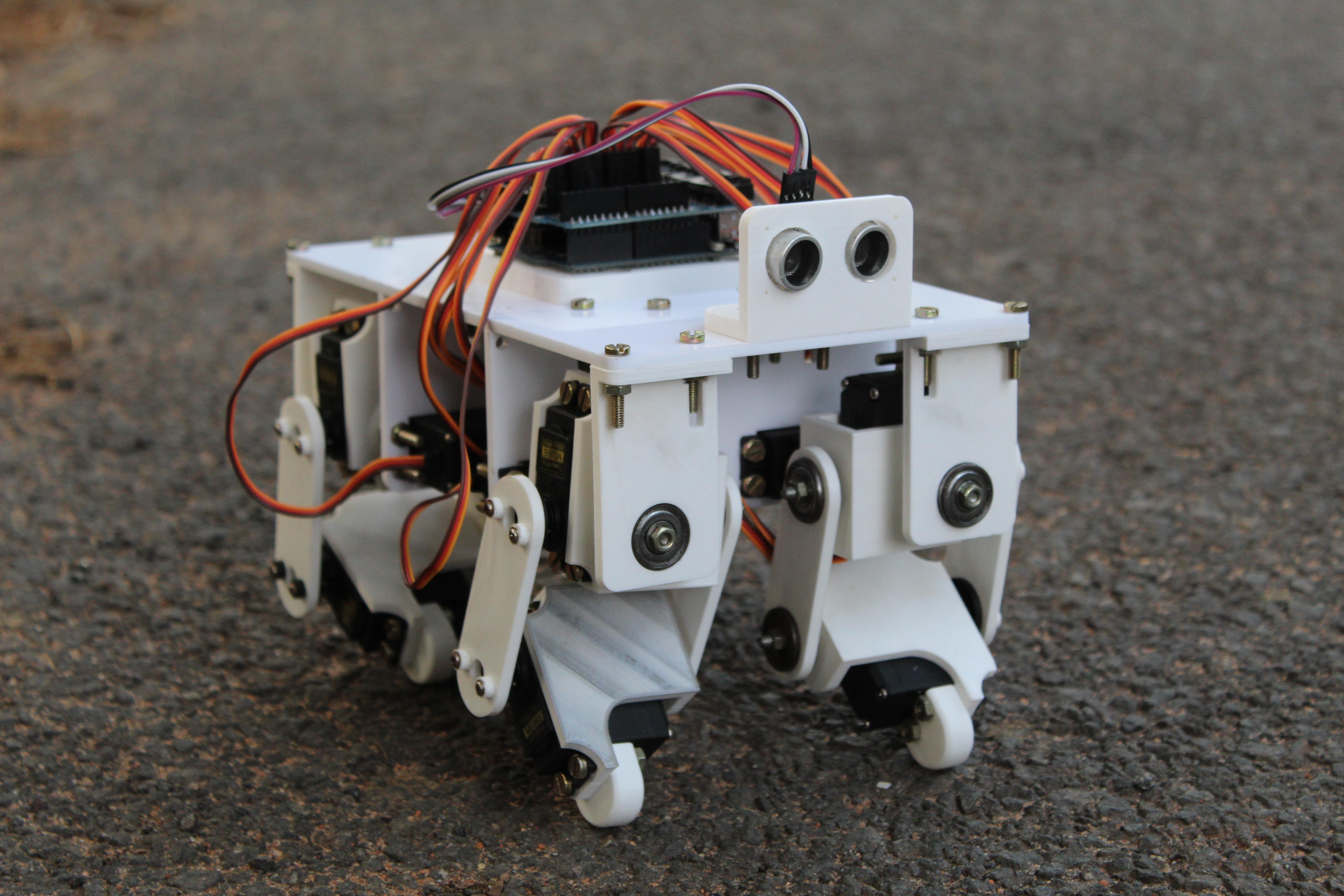
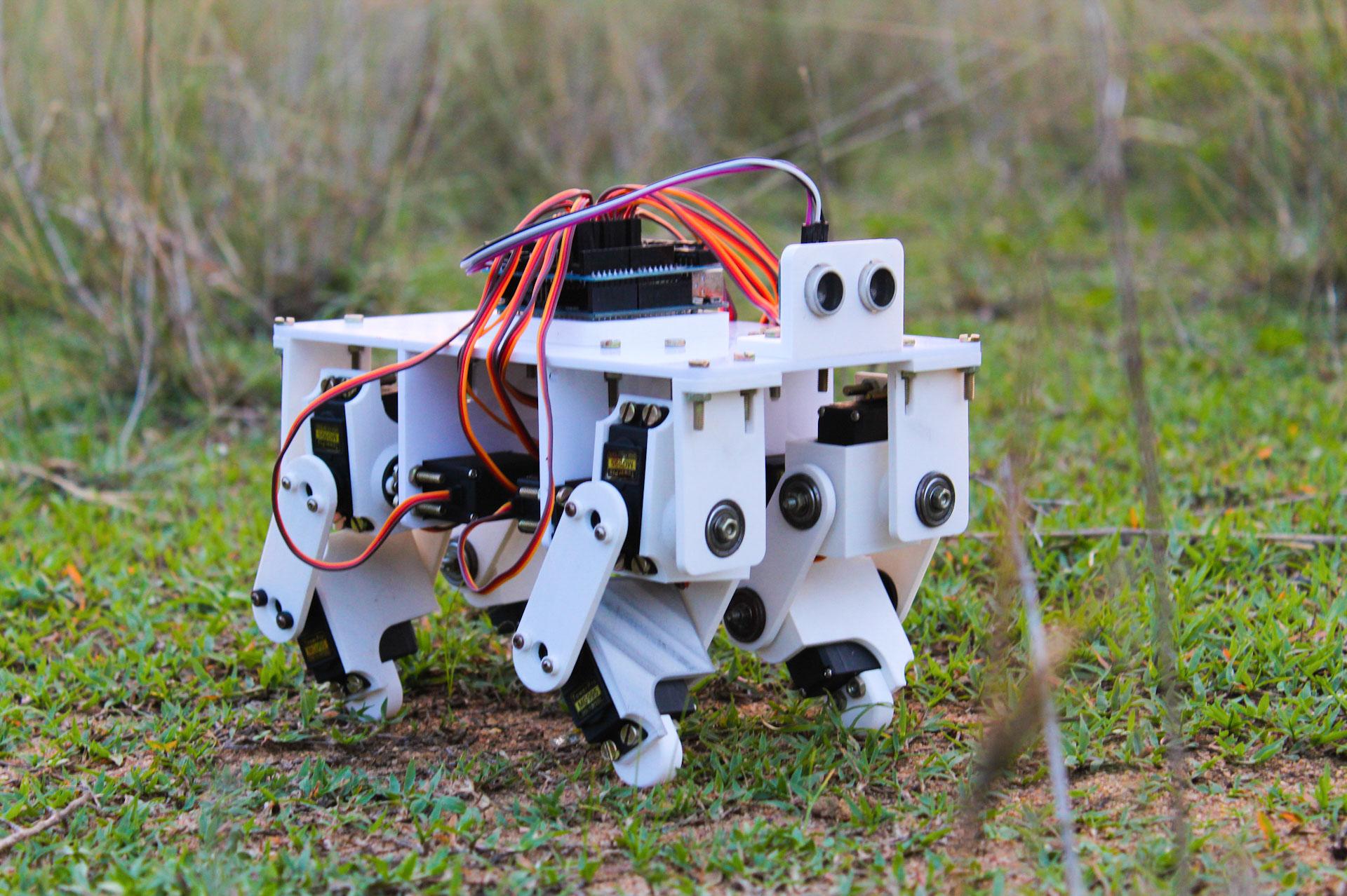
Step 1: general information and design process
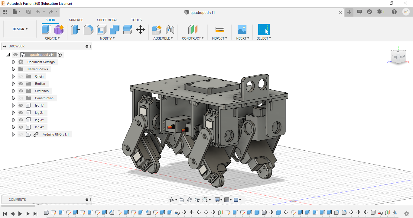
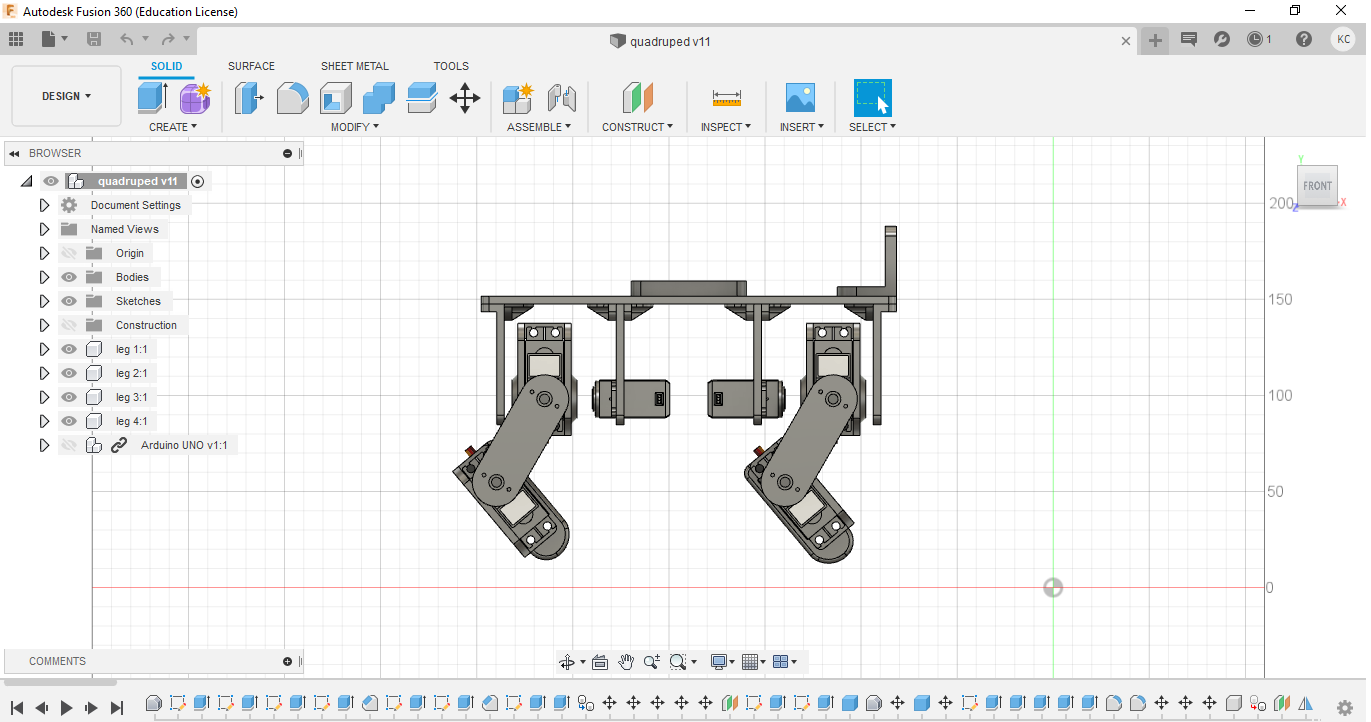
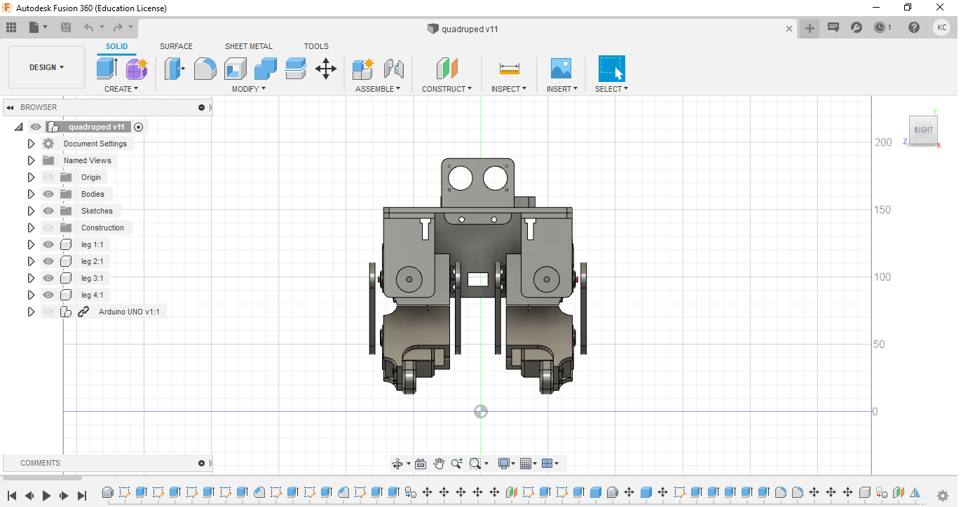
I developed the robot in the free 3D modeling software from Autodesk, Fusion 360. I started by importing the servo motors around which I drew legs and a torso. Then I designed the motor holding brackets to give them a second attachment point, diametrically opposed to the shaft. Shafts on each side of the motor give the structure strength and eliminate the possibility of skewing when the legs are loaded. The bearings are inserted into special holders, and bolts are used as the shaft in the brackets. After the holders are attached to the shafts with a nut, the bearing provides a secure pivot point on the opposite side of the servo motor from the shaft.
Another goal during development was to make the model as compact as possible in order to make the most of the torque of the servo motors. The arms were sized to provide maximum mobility with minimum length. If I made them too short, the brackets would collide with each other, which would reduce mobility. If made too long, the motors would have to apply unnecessary torque. Last but not least, I designed the robot case with attachments for the Arduino and other electronic components. I have provided additional mounts on the top of the panel to expand the project in the future. Someday it will be possible to add distance sensors, cameras or other mechanisms for the robot, for example, grippers.
Step 2: materials needed
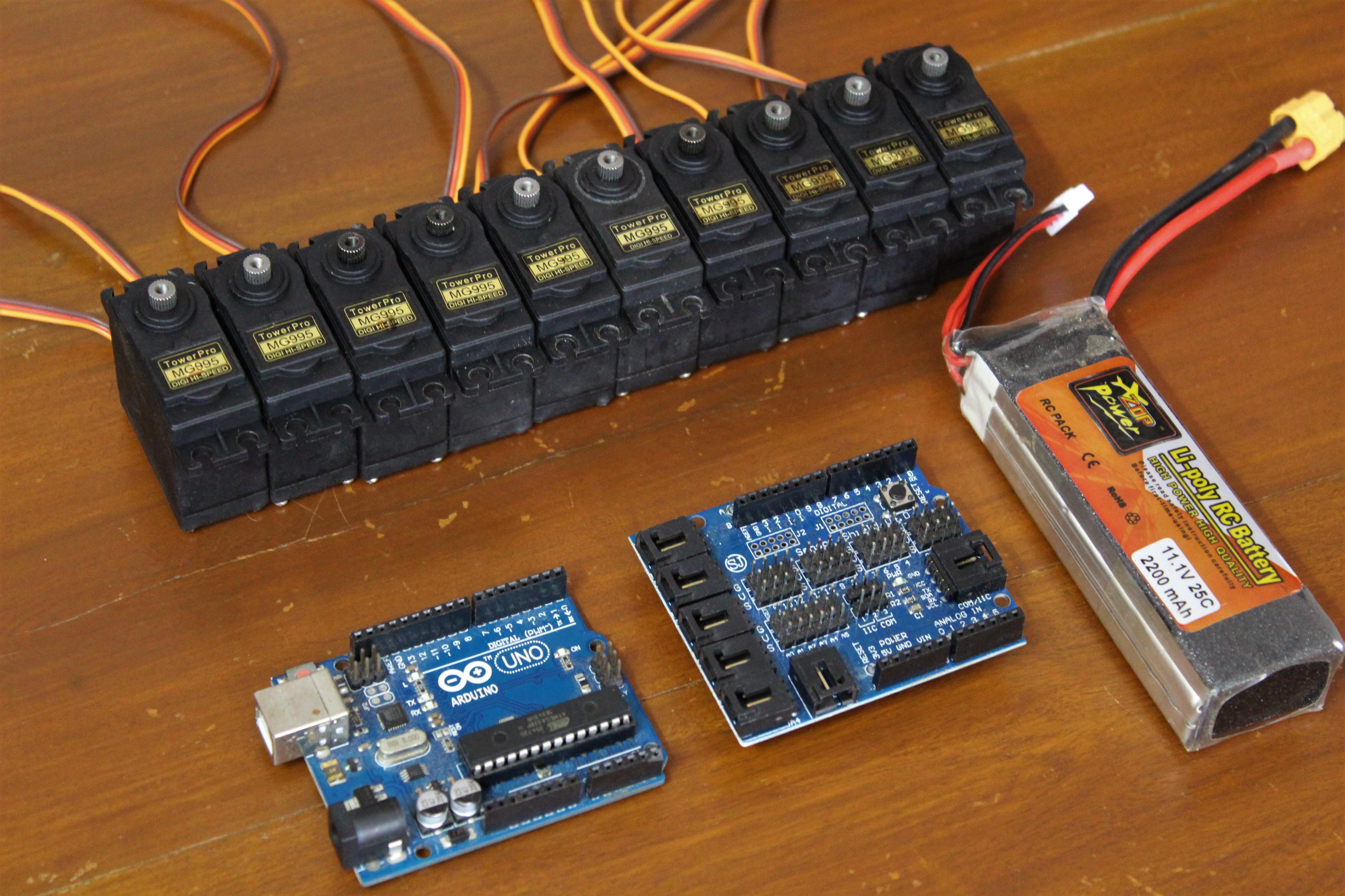
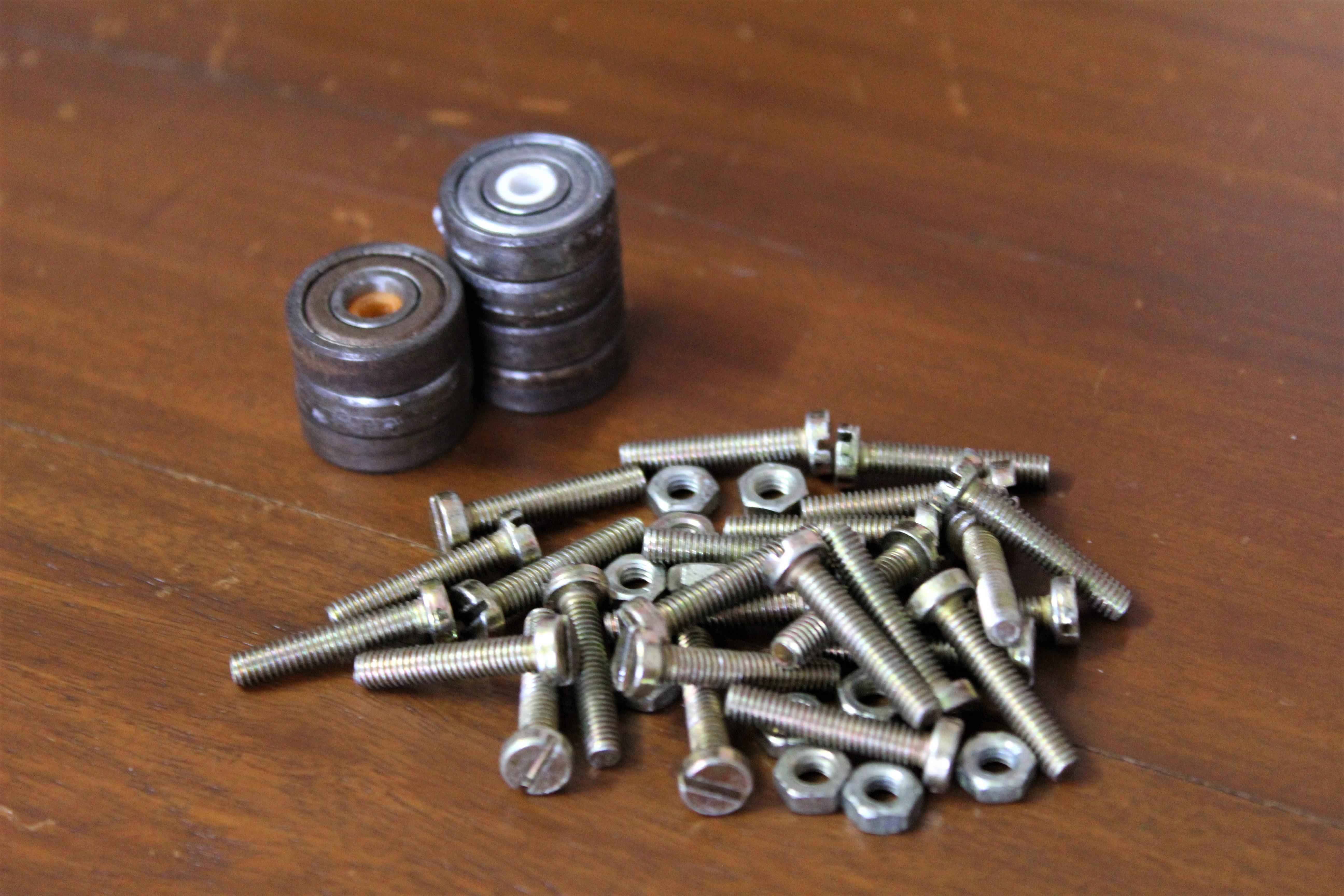
List of required materials to create your own quadruped robot powered by Arduino. All components are common and available.
Electronics:
- Arduino Uno x 1.
- Towerpro MG995 servo motor x 12.
- Arduino Sensor Shield (I have version 4, but I recommend buying version 5).
- Connecting wires, 10 pcs.
- MPU6050 IMU (optional).
- Ultrasonic distance sensor (optional).
Components:
- Bearings (8x19x7 mm, 12 pcs.).
- Bolts and nuts M4.
- Plastic for a 3D printer.
- Plexiglass 4 mm.
Tools
- 3D printer.
- Laser cutter.
Most of the waste is spent on 12 servo motors. I still recommend not using cheap plastic motors as they break too easily. Except for the tools, everything together cost me $ 60.
Step 3: printed components
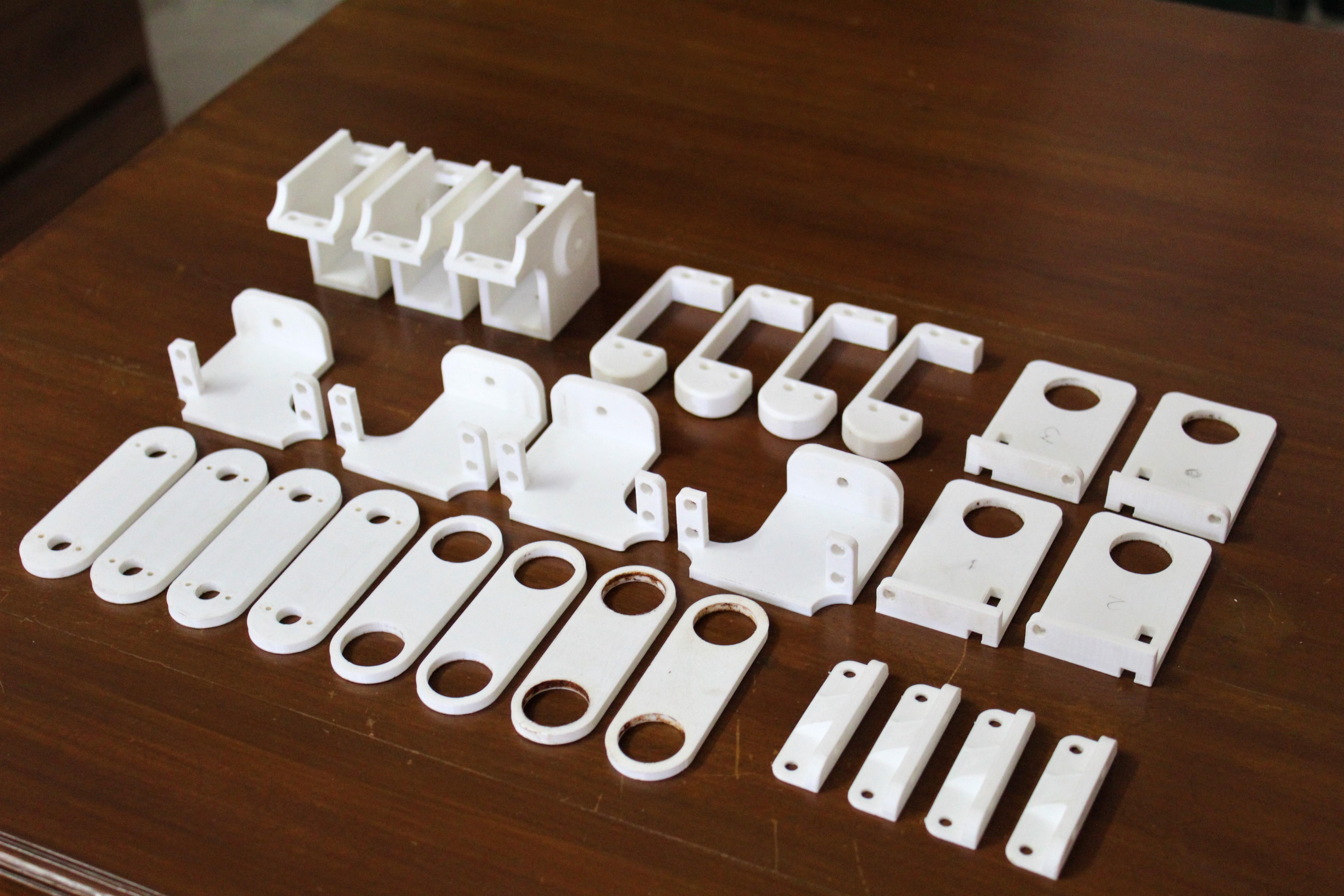
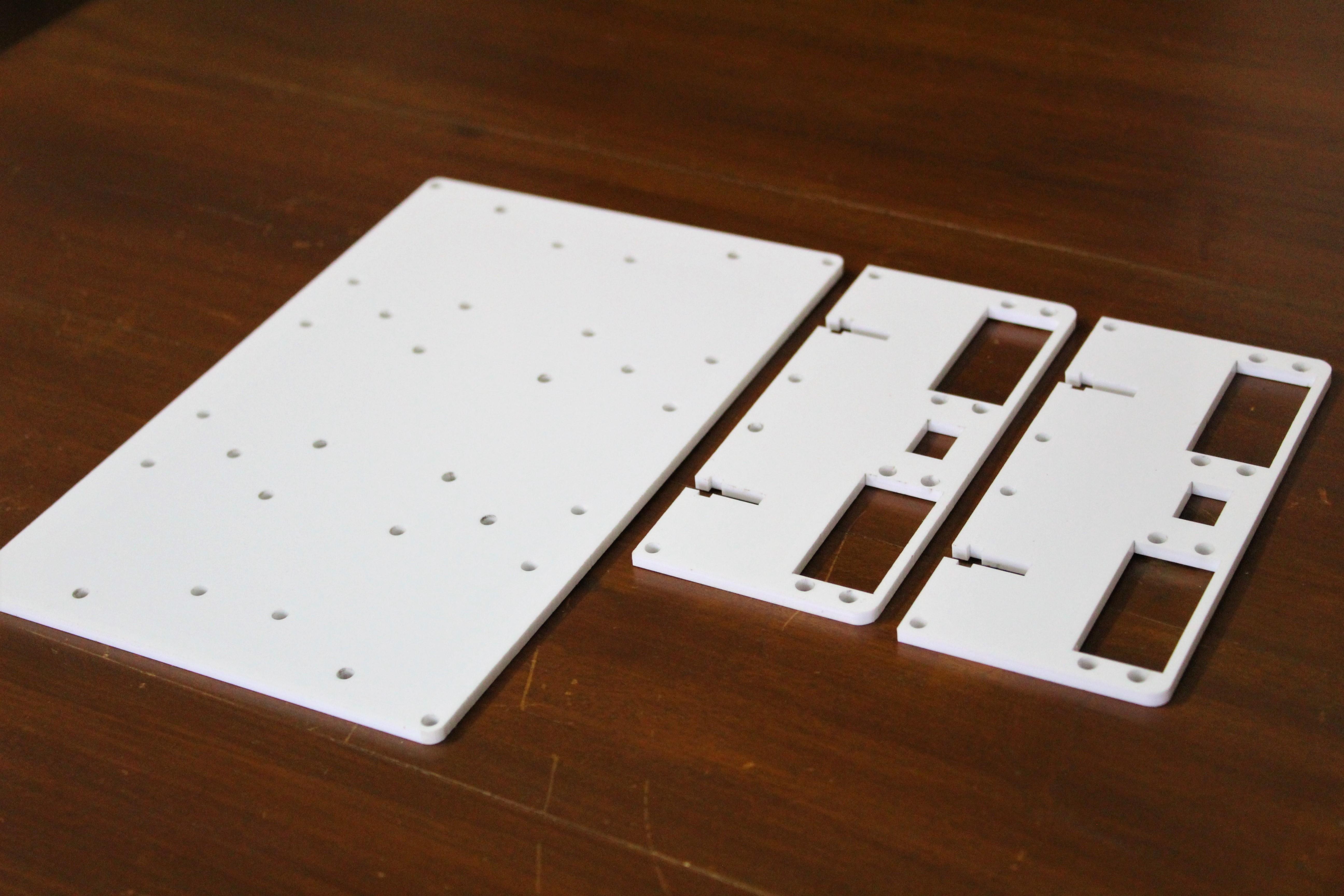
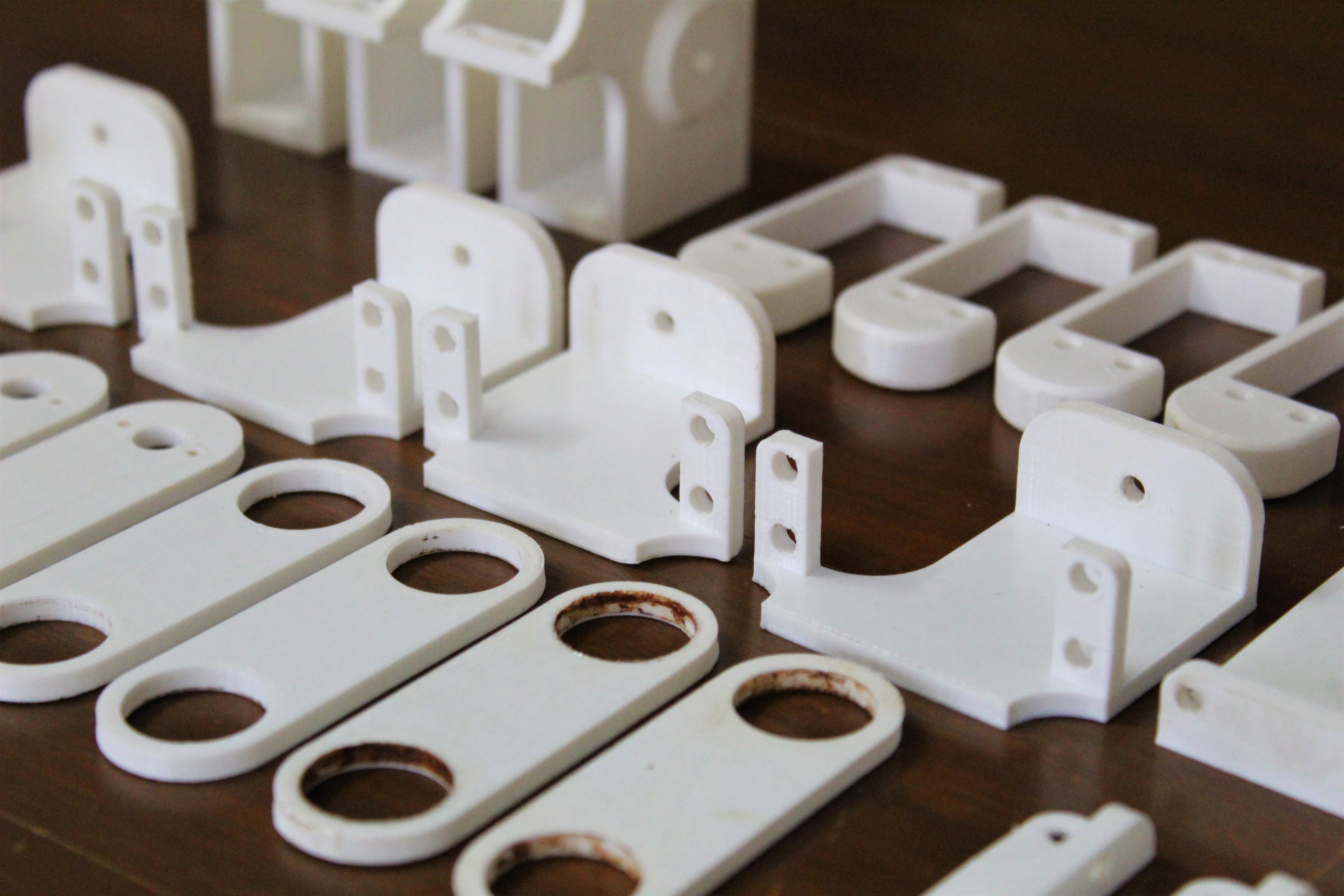
The components of the robot had to be specially developed - for this we took advantage of the capabilities of digital design and CAD. Most of the components are 3D printed and some are cut from 4mm plexiglass sheet. Printed at 40% coverage, 2 perimeters, 0.4 mm nozzle, 0.1 mm layer height with PLA. Some of the components require props due to their complex shape with overhanging parts, but they are accessible and easy to remove with wire cutters. You can choose the color according to your taste. Below is a list of components and STL links for printing, as well as 2D drawings for the cutter.
Components for 3D printing:
- Femoral servo motor bracket x 2.
- Femoral servo motor mirror bracket x 2.
- Knee servomotor bracket x 2.
- Mirror servo motor knee bracket x 2.
- Bearing holder x 2.
- Mirror bearing holder x 2.
- Legs x 4.
- Servo motor holders x 4.
- Bearing holders x 4.
- Arduino hardware x 1.
- Distance sensor fixture x 1.
- Corner fasteners x 4.
- Bearing sleeve x 4.
- Servo washer x 24.
Components for laser cutting:
- Servo Mounting Panel x 2.
- Top panel x 1.
There are a total of 30 parts to print, excluding the various washers, and the total number of digitally produced parts is 33. I printed everything in 30 hours.
content.instructables.com/ORIG/FBK/9YPN/KFZEKVED/FBK9YPNKFZEKVED.rar
content.instructables.com/ORIG/FZS/65E0/KFZEKVEE/FZS65E0KFZEKVEE.pdf
Step 4: preparing the bearing holders
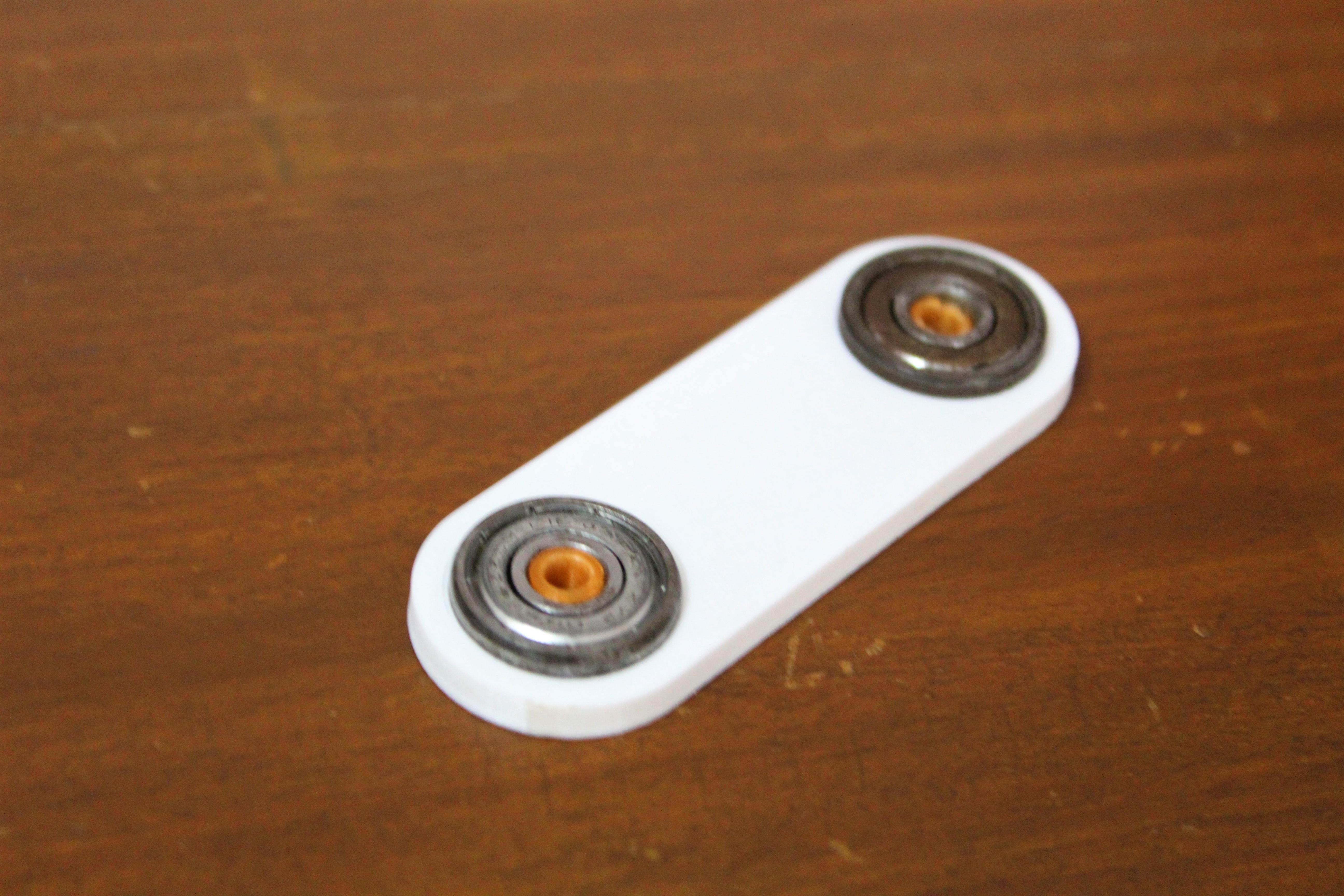
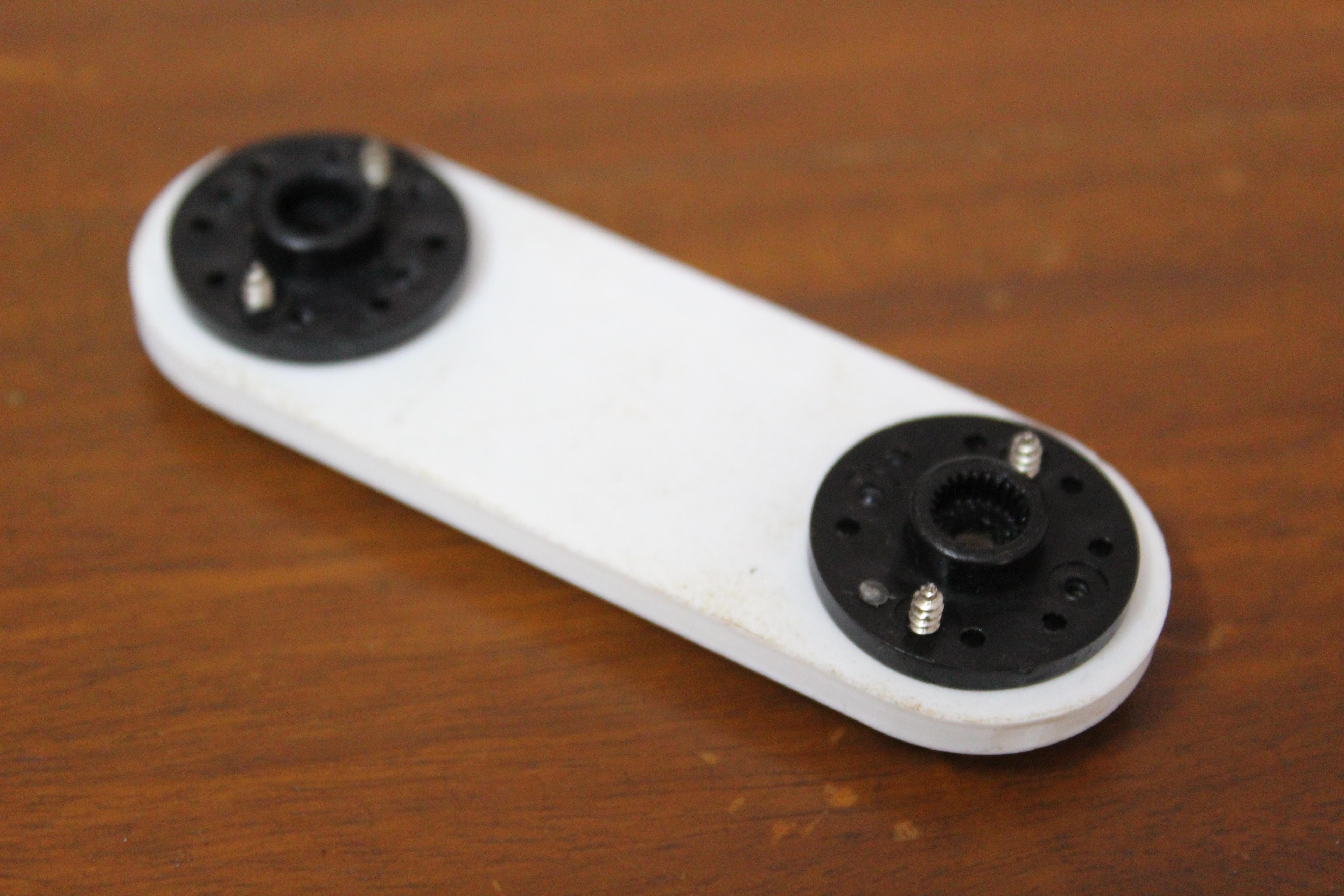
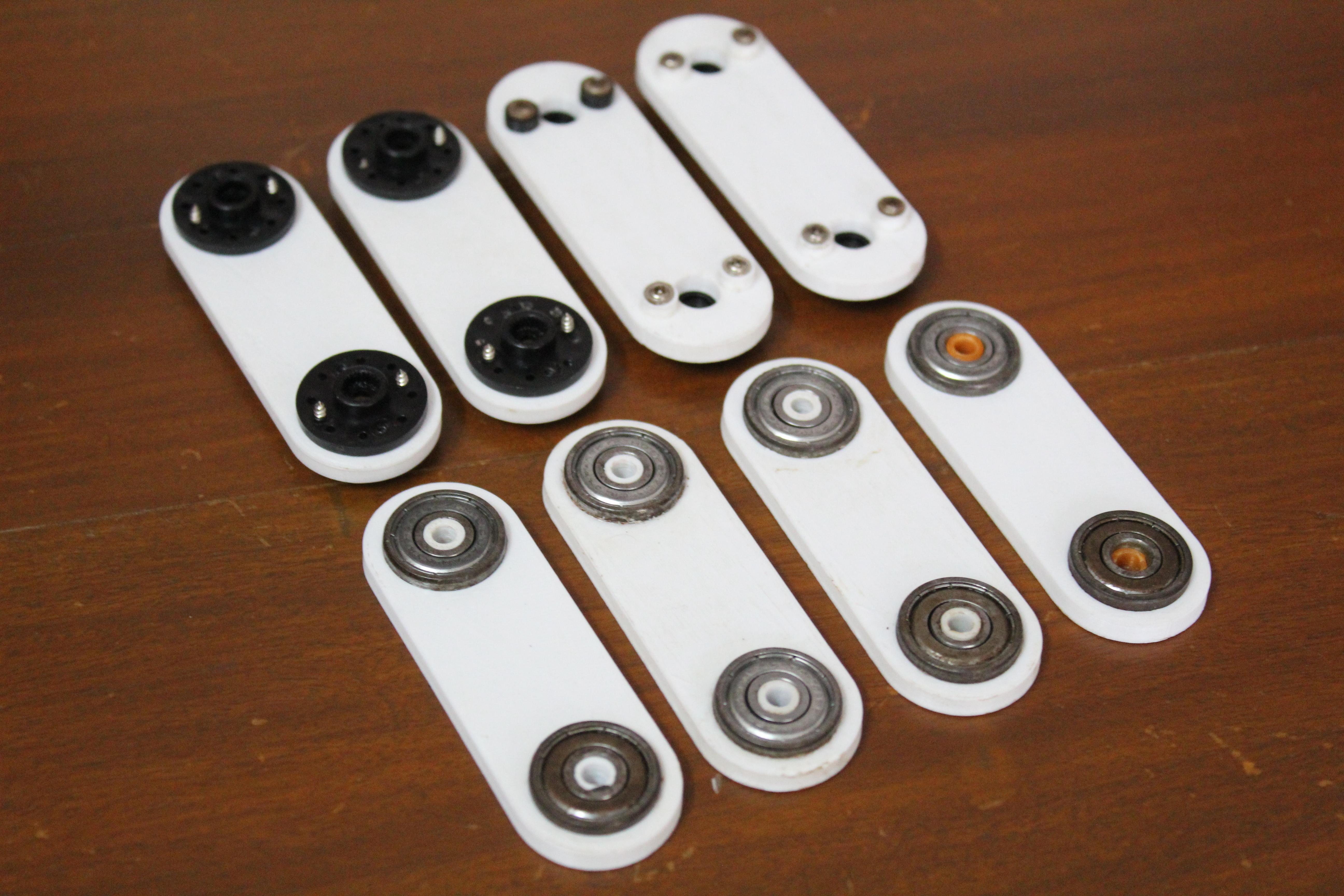
If you start assembling with certain components, then the whole process will go faster. You can start with the holders. To do this, first sandpaper the holes inside the holder, and then insert the bearing into it flush. I had to 3D print a few washers because the bolts that came with the motors were too long and would hit the motors during operation.
Step 5: prepare the servo motor brackets
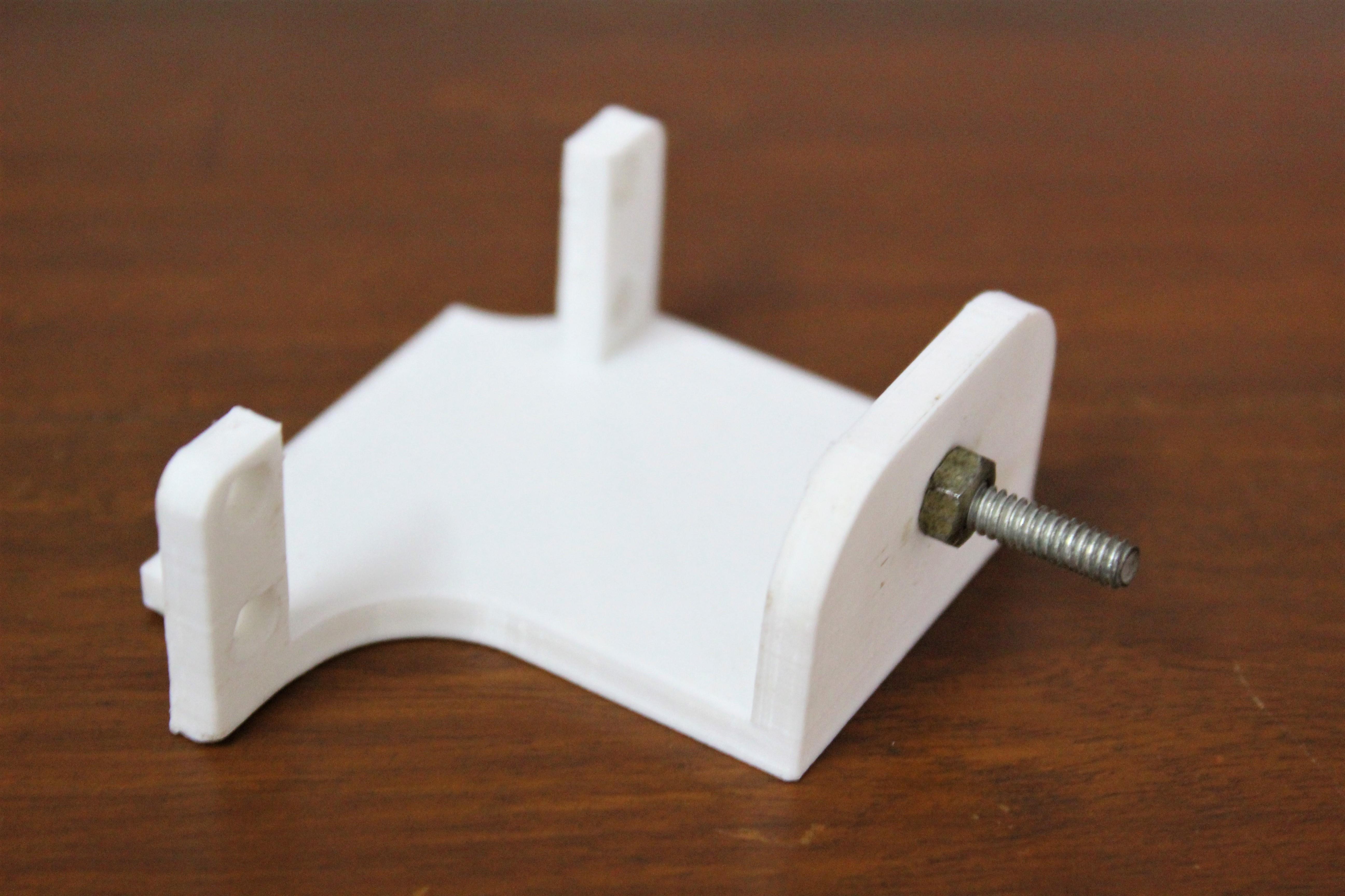
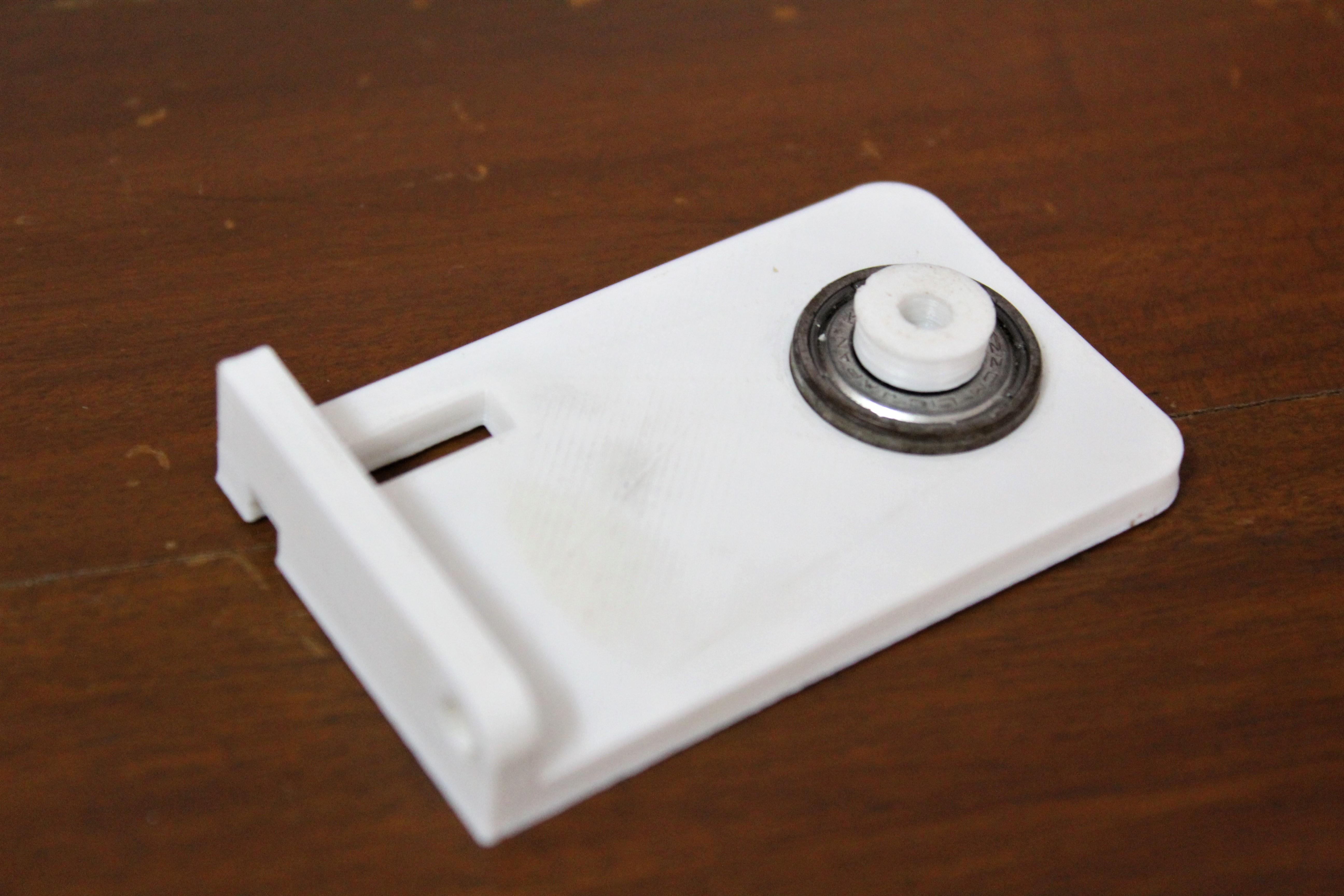

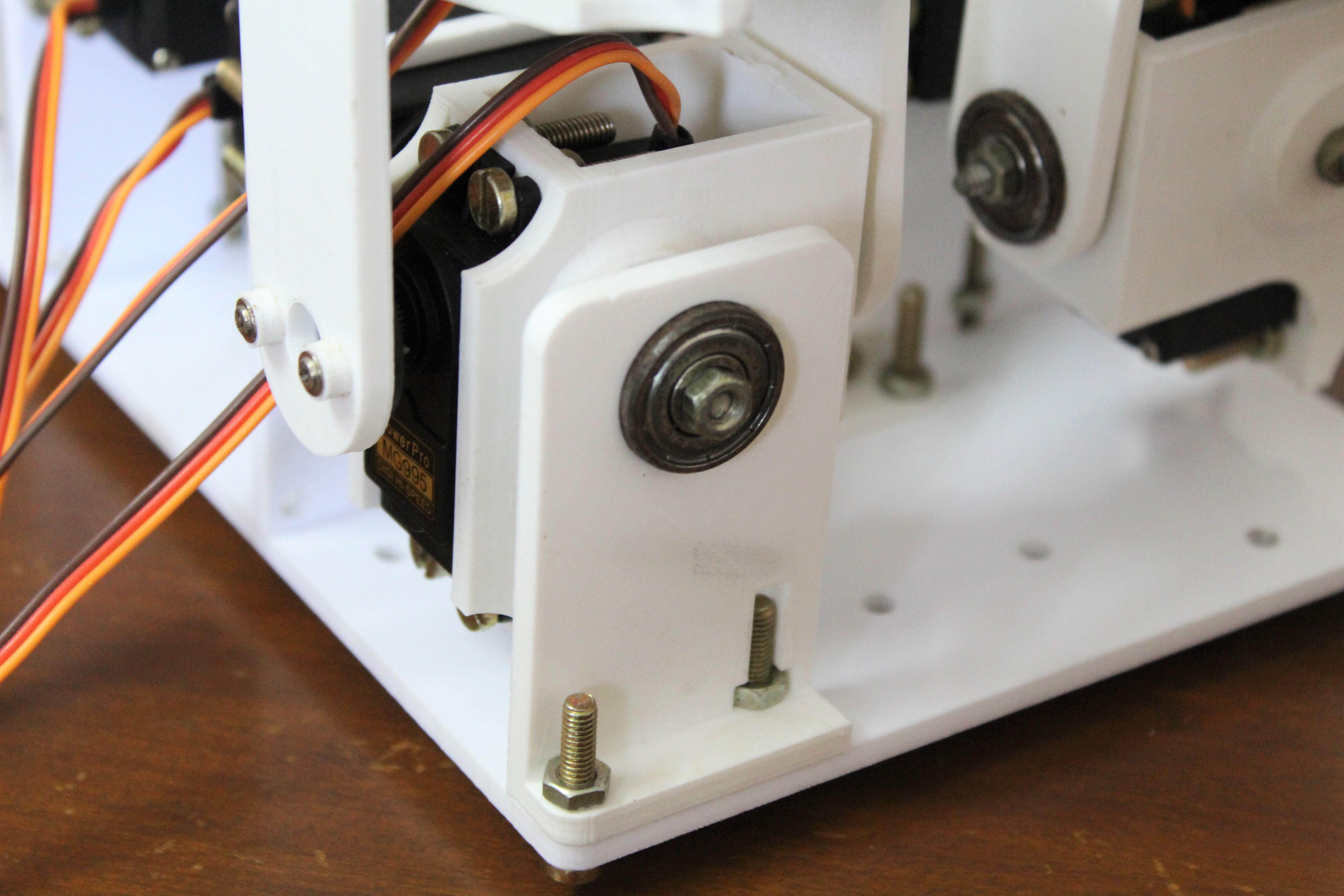
To assemble the knee brace, simply insert the bolt into the hole and tighten with the nut. This joint will act as the second axis of the motor. Thread the two bolts through the holes in the thigh brace and tighten with the nuts. Then take the bent servo bracket and attach it to the raised part of the bracket with two nuts. Finally, take the bearing sleeve and insert the bearing into it. You may need to sand the inner surface of the sleeve a little. The attached photos show the different stages of assembly.
Step 6: assembling the legs
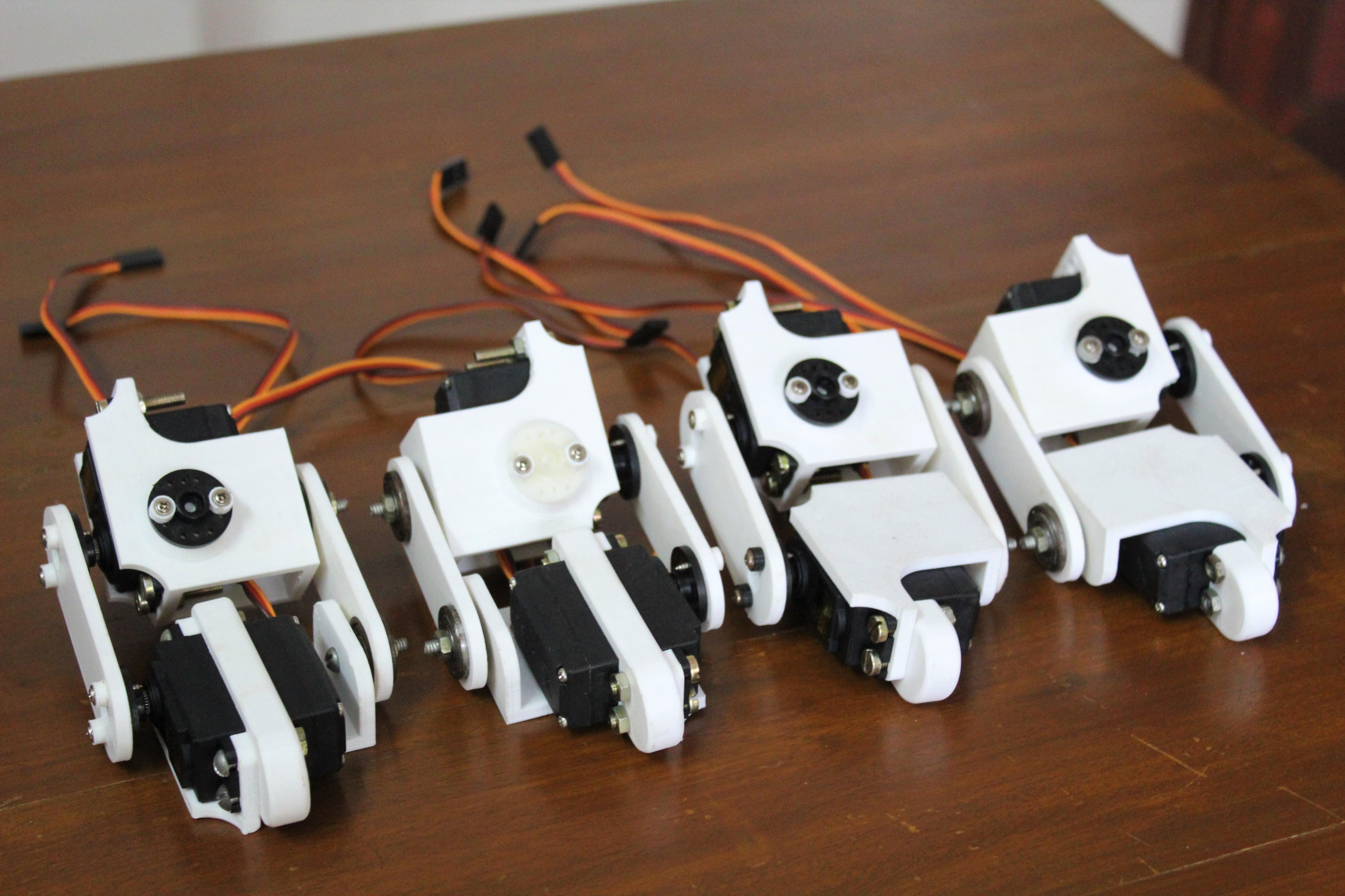
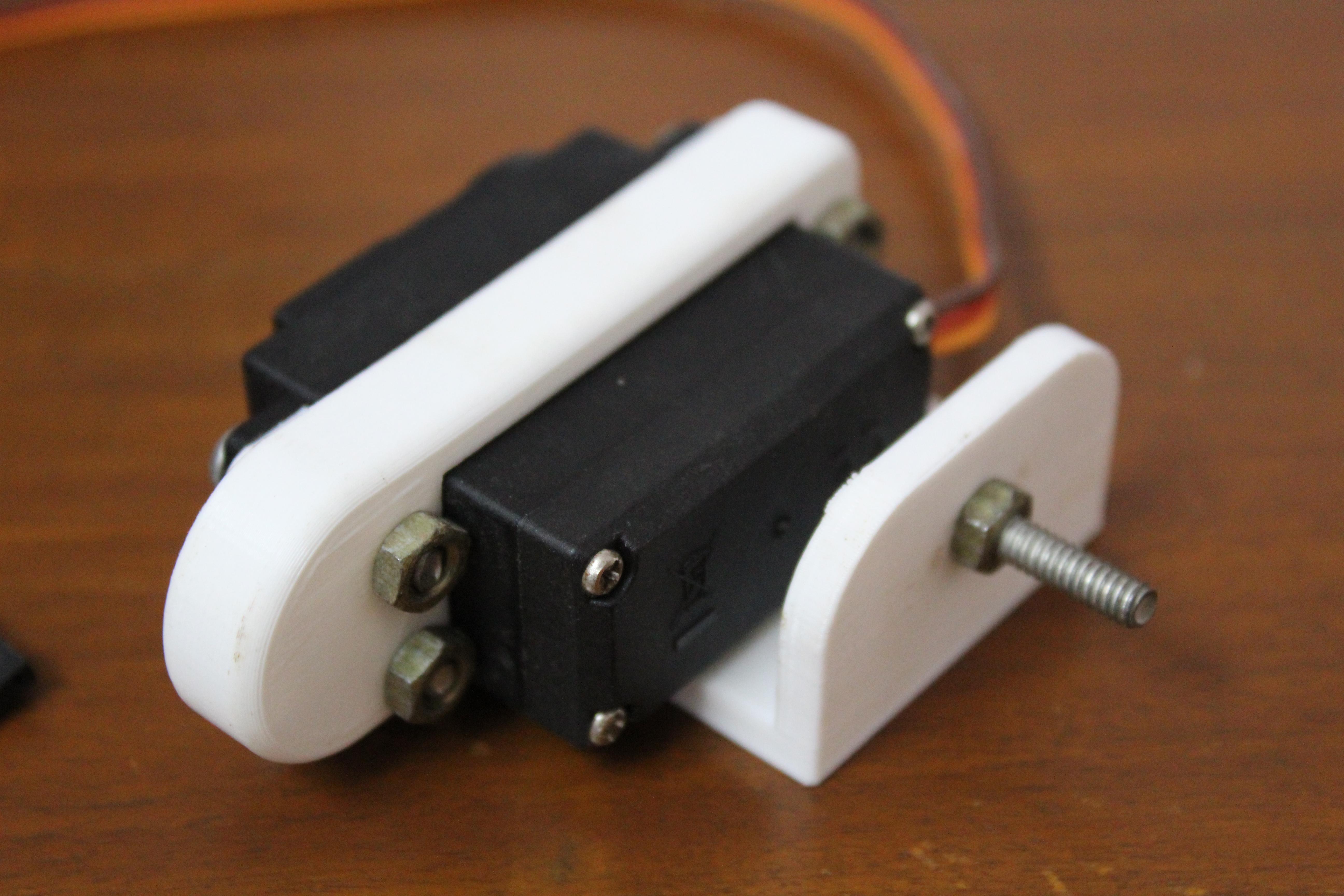
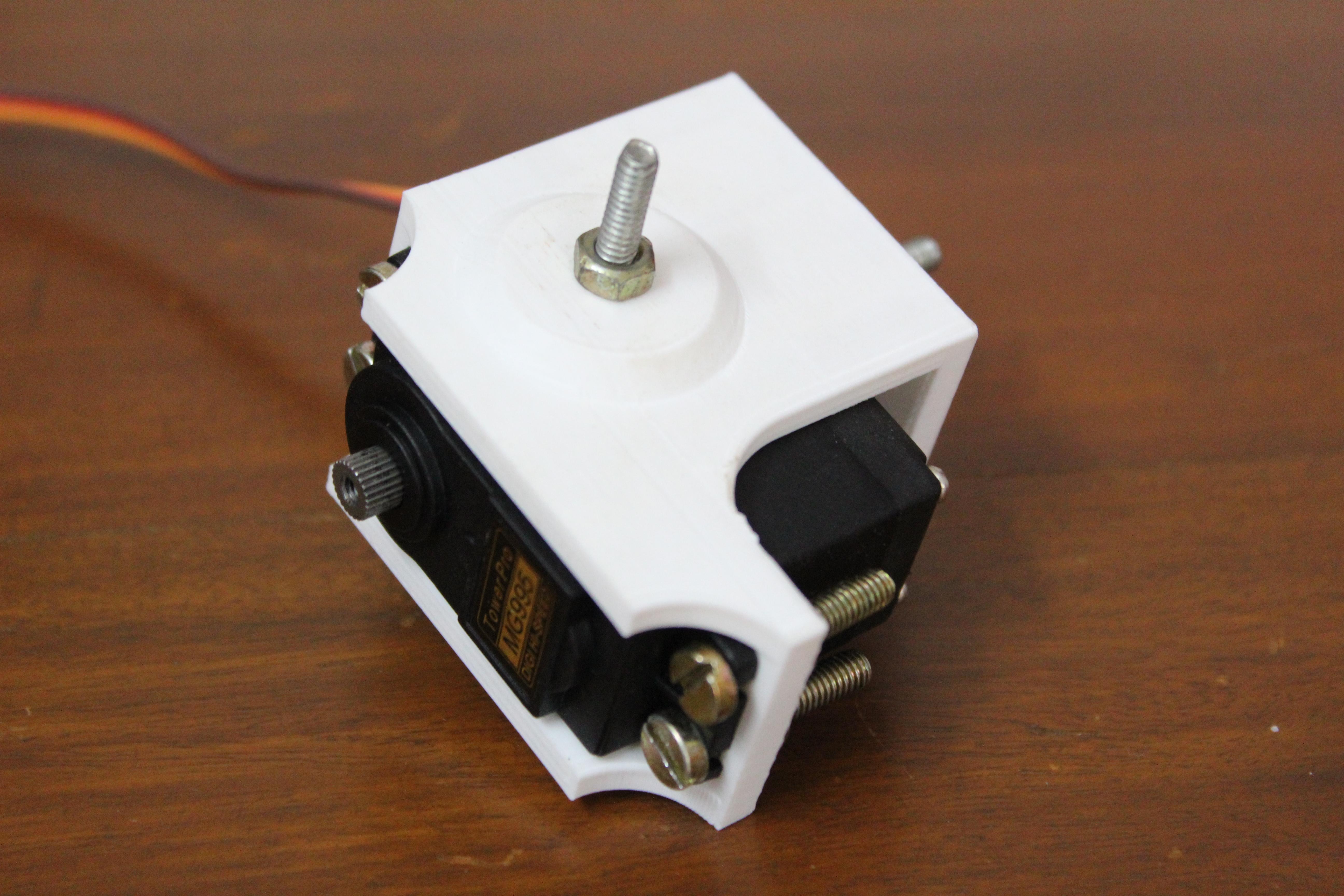
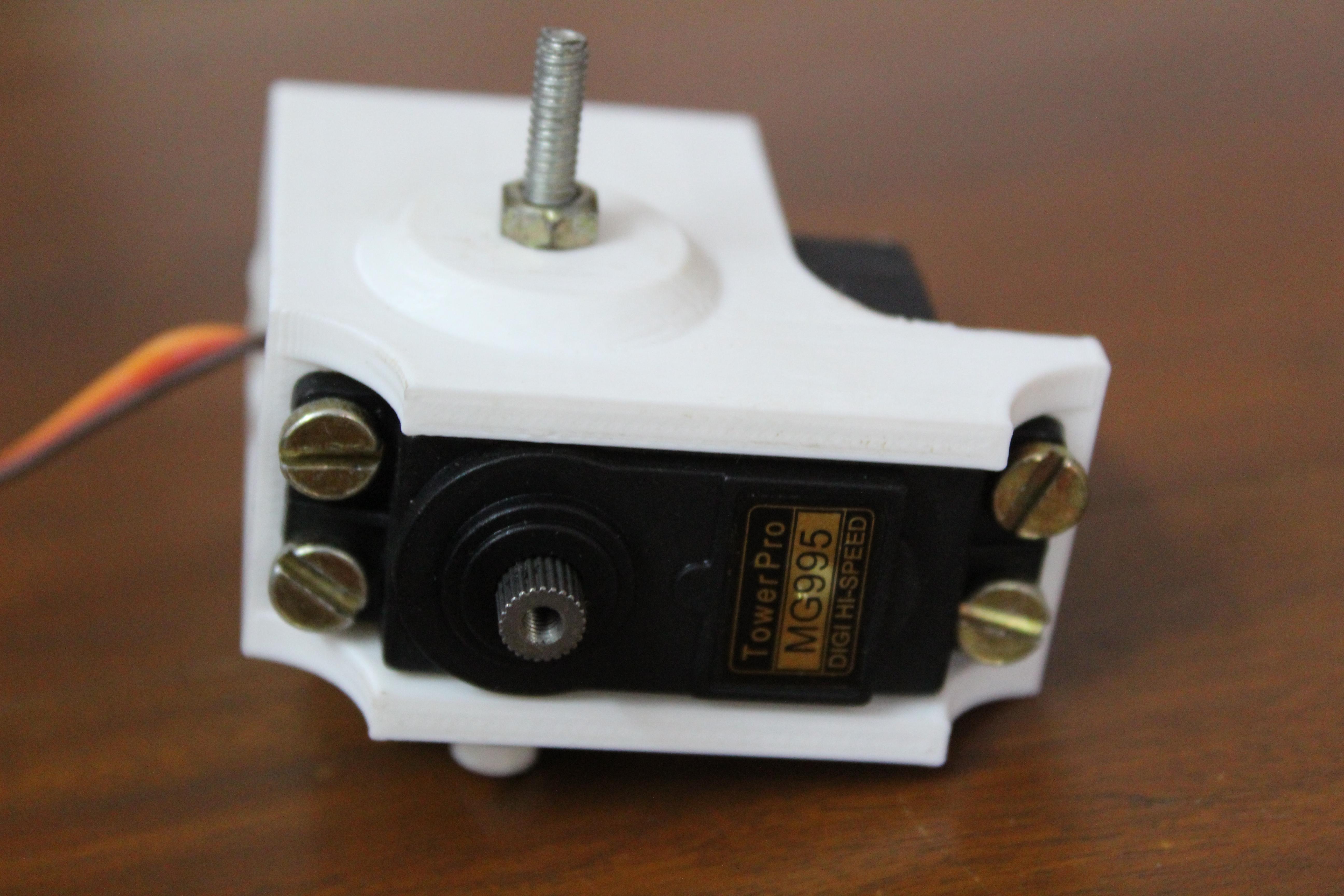
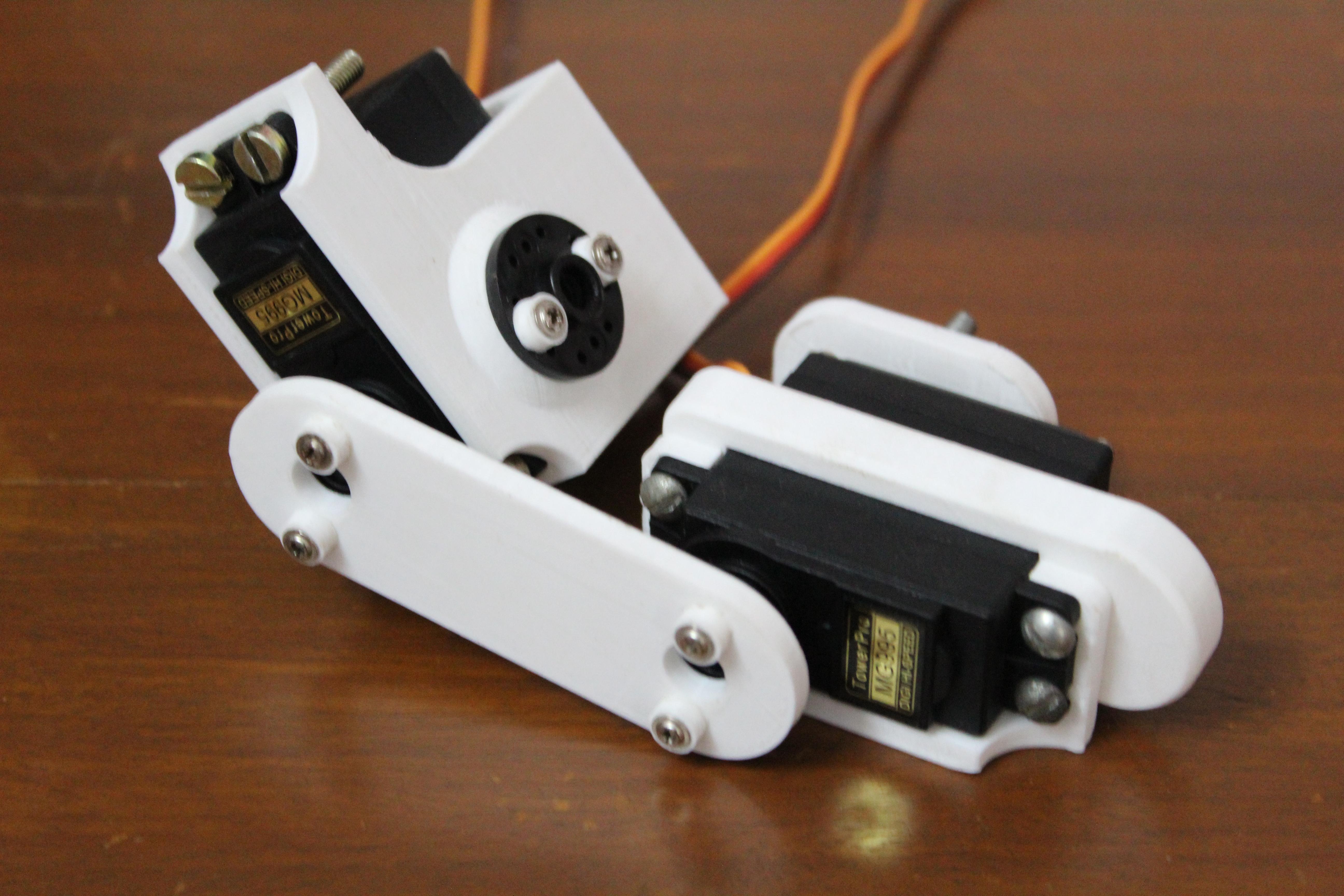
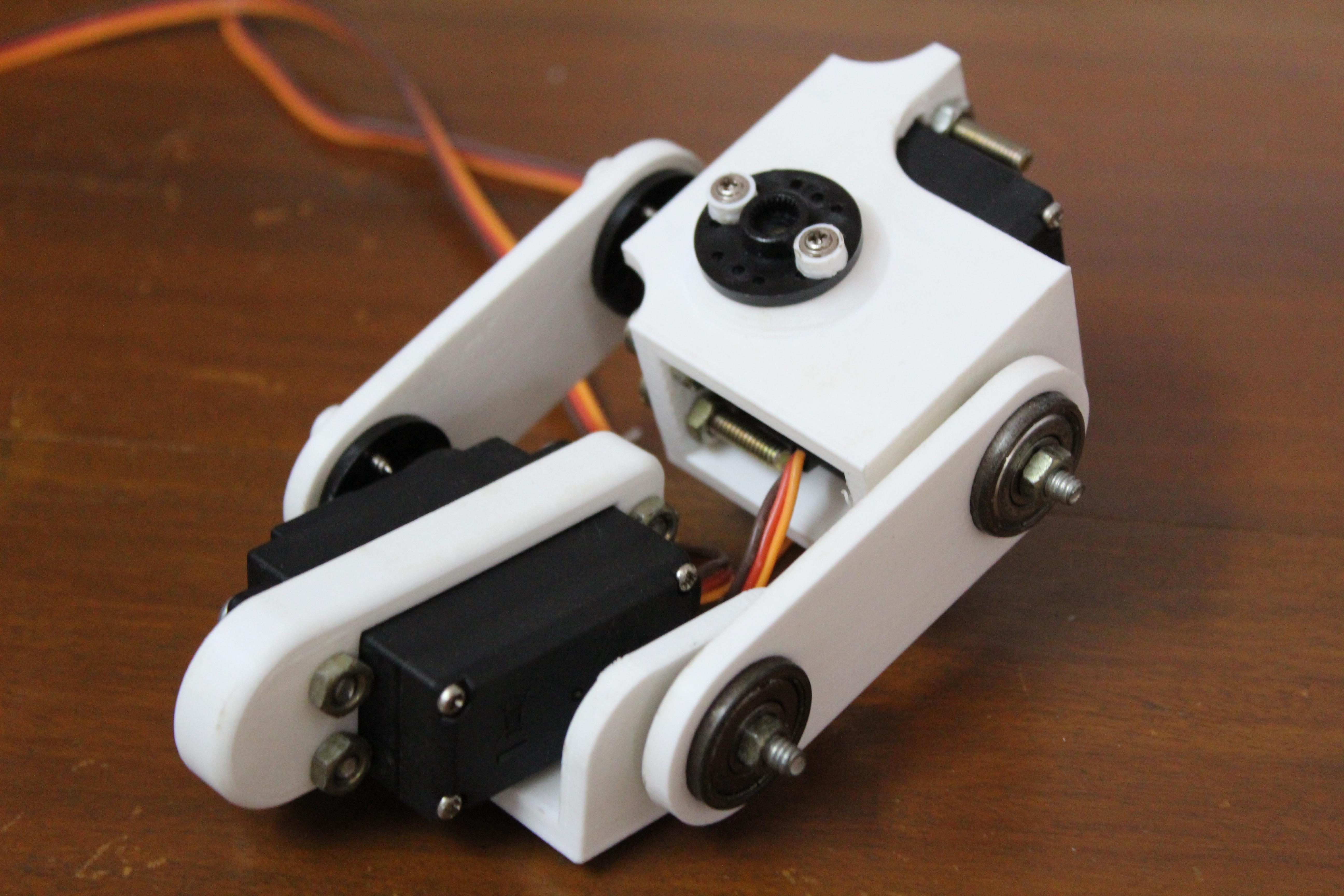
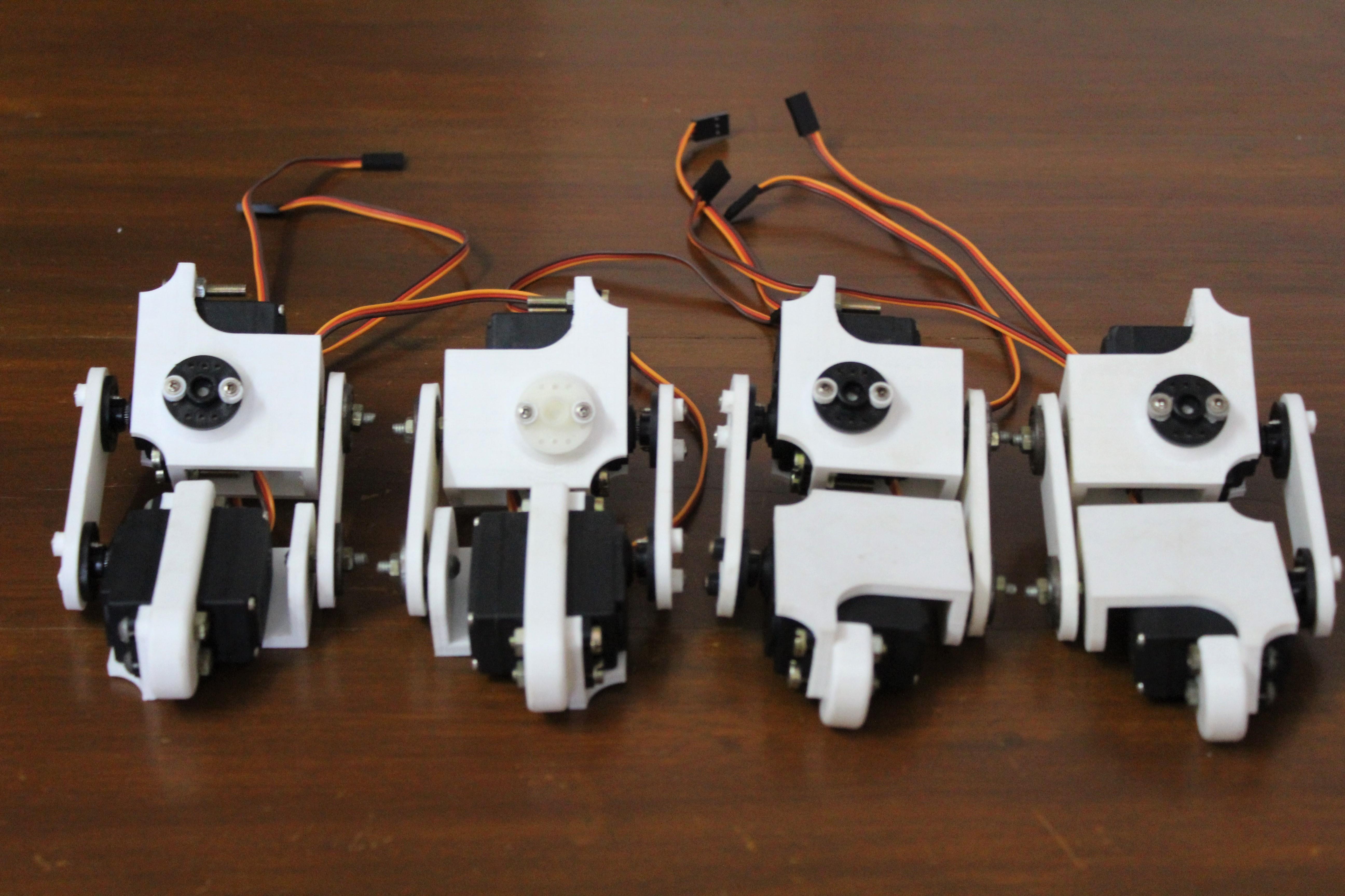
Once you have all the braces and holders assembled, you can start assembling your legs. First screw the servomotors onto the brackets with screws and nuts. Align the motor shaft with the bolt protruding from the other side.
Then connect the thigh servomotor to the knee servomotor with the holder. Do not tighten the nut just yet - later, you may need to trim something. On the other side, secure the holders with two bearings to the protruding bolts with nuts.
Collect all four legs like this.
Step 7: assembling the torso
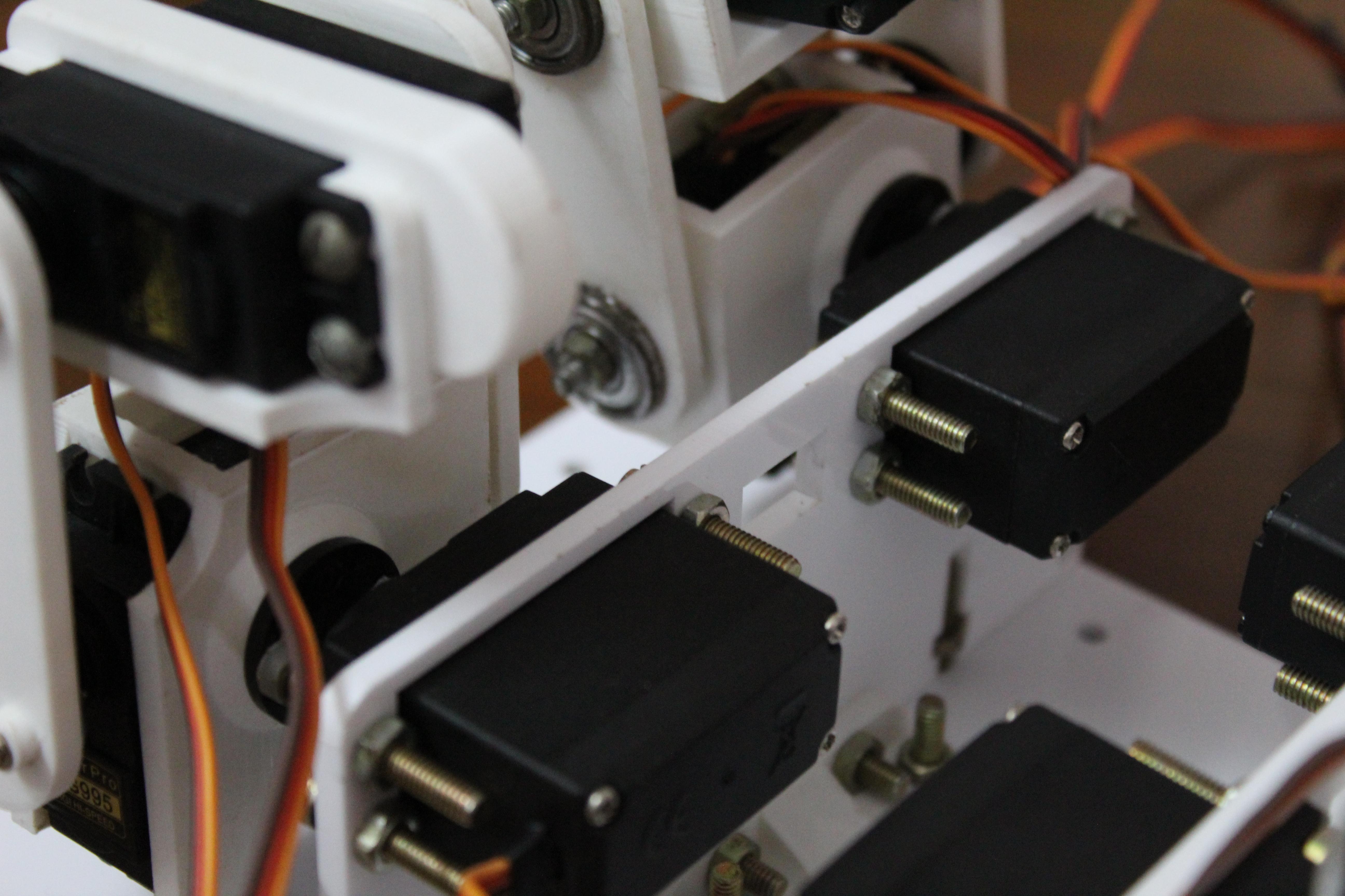
Now you can start assembling the torso. It contains four servo motors giving the third degree of leg freedom. Start with 4 M4 bolts that secure the motors to the laser cut panel.
Mount the servomotors so that the axles point outwards - see photos.
Then bolt the corner brackets on both sides of the panel. They help to securely attach the motor mount panel to the top panel.
With all holders secured, attach the motor panel to the top panel. Start with the outer bolts located at the front and back. The bolts in the middle hold the Arduino mount at the same time. See photos at the beginning of the section. Attach the Arduino panel to the top panel so that the bolts go through the holes in the corner brackets.
Step 8: putting it all together

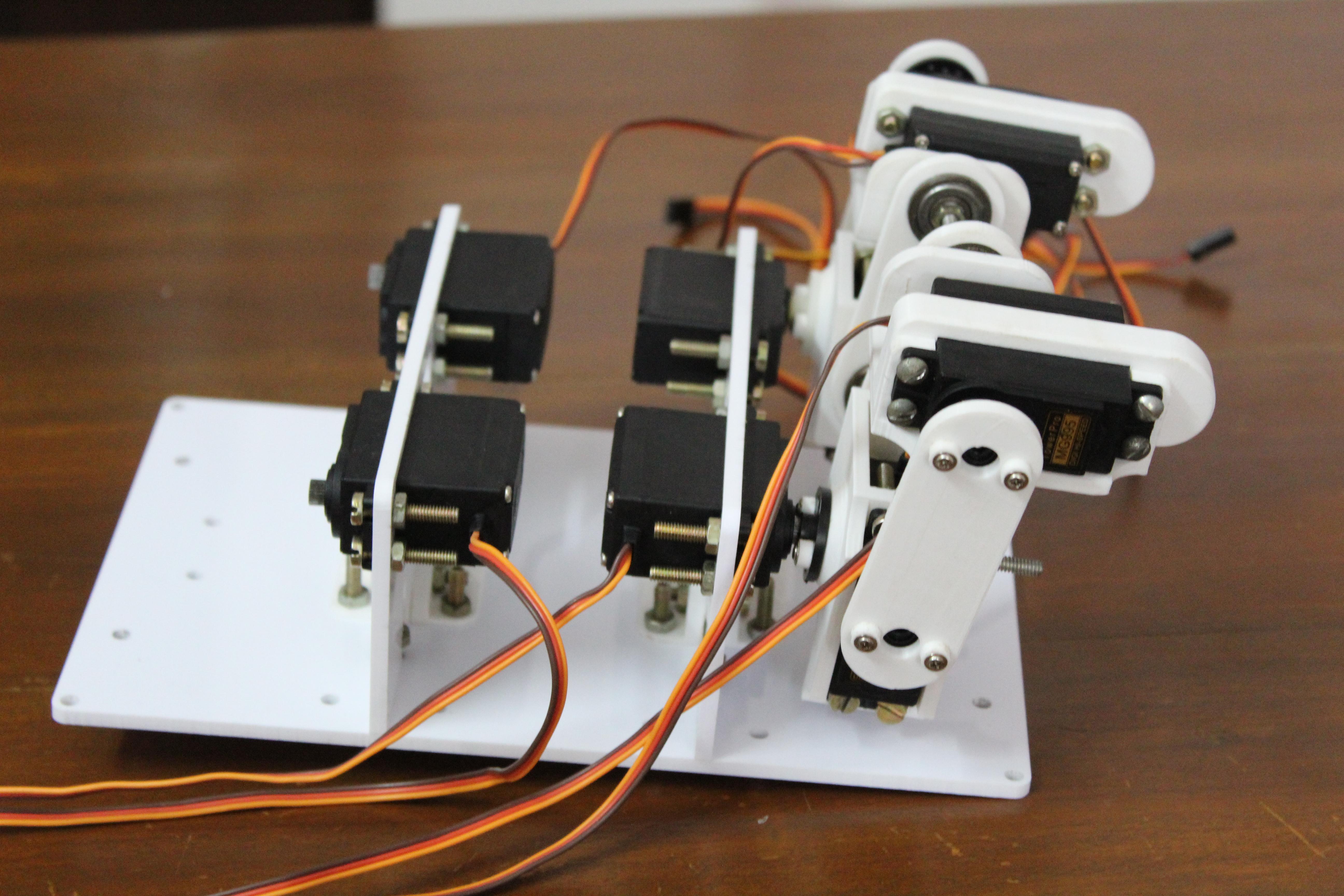
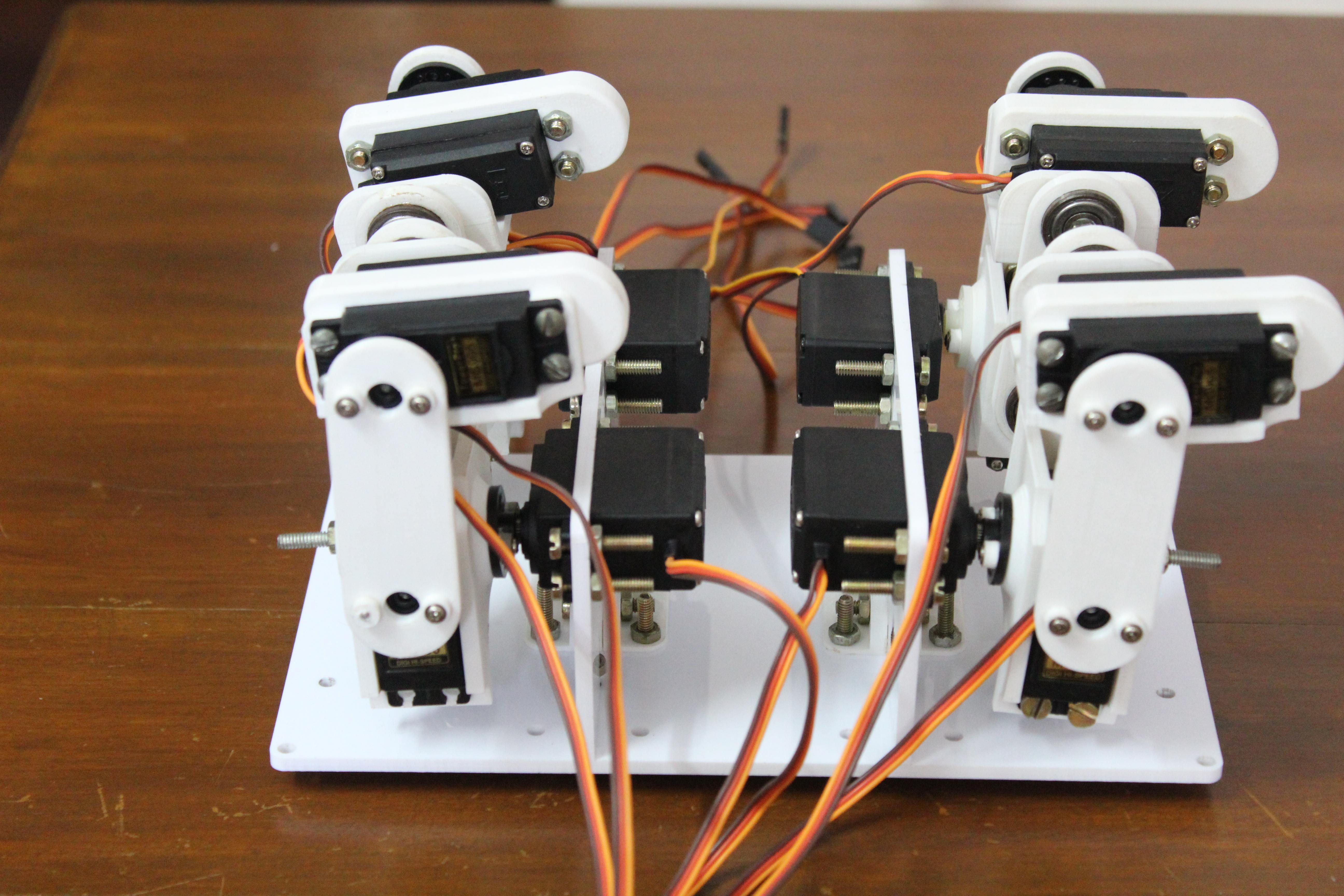
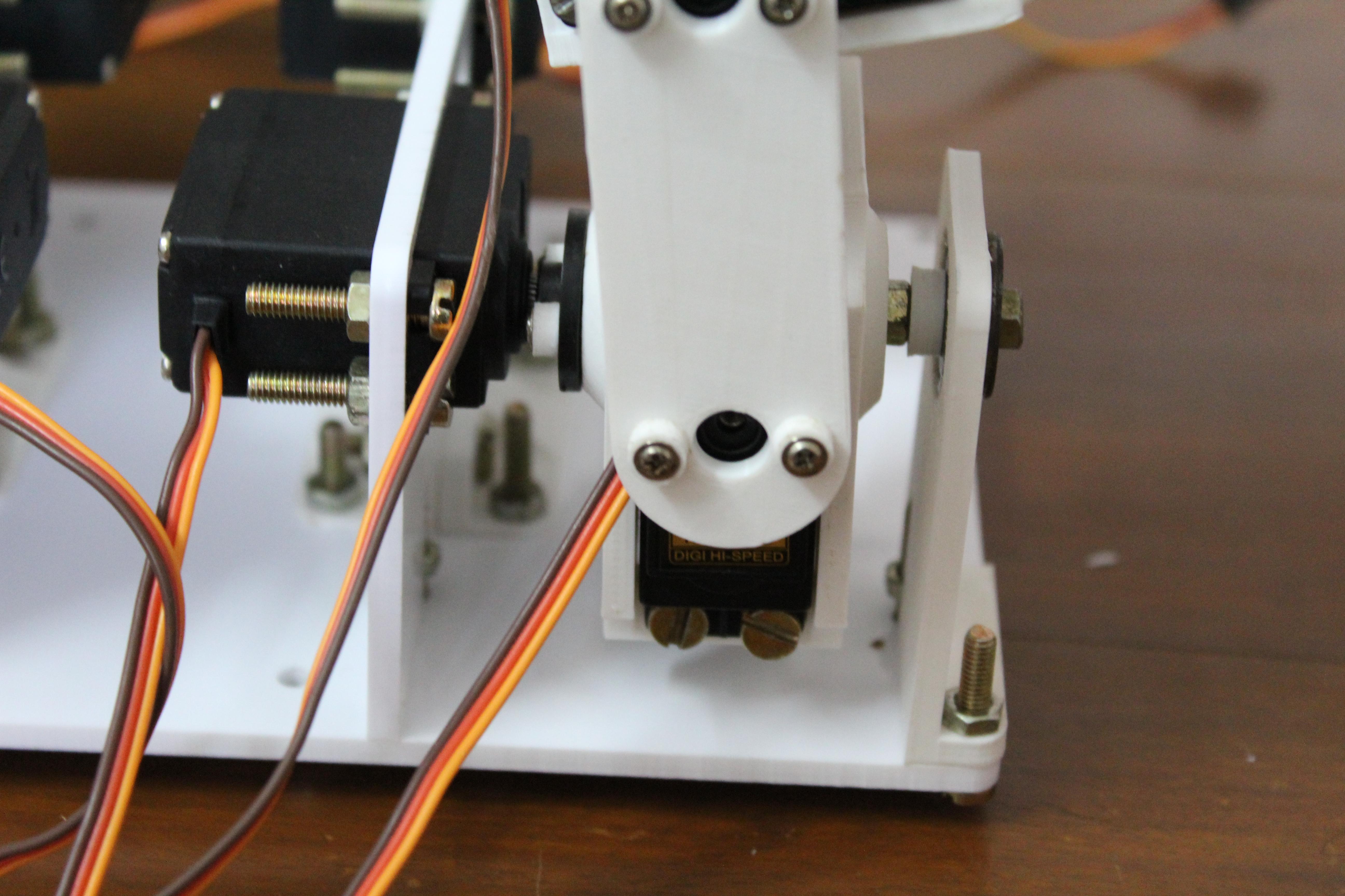
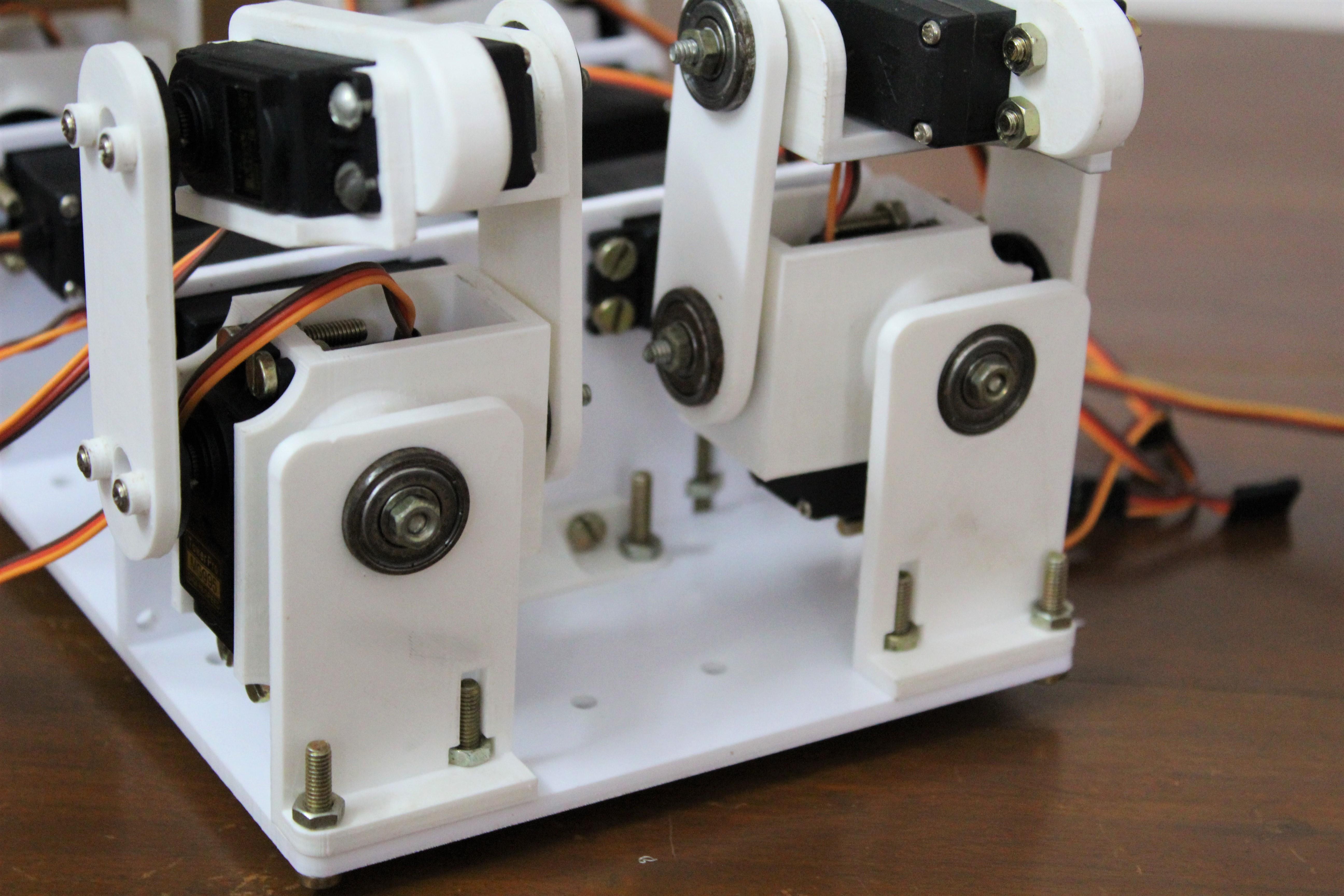
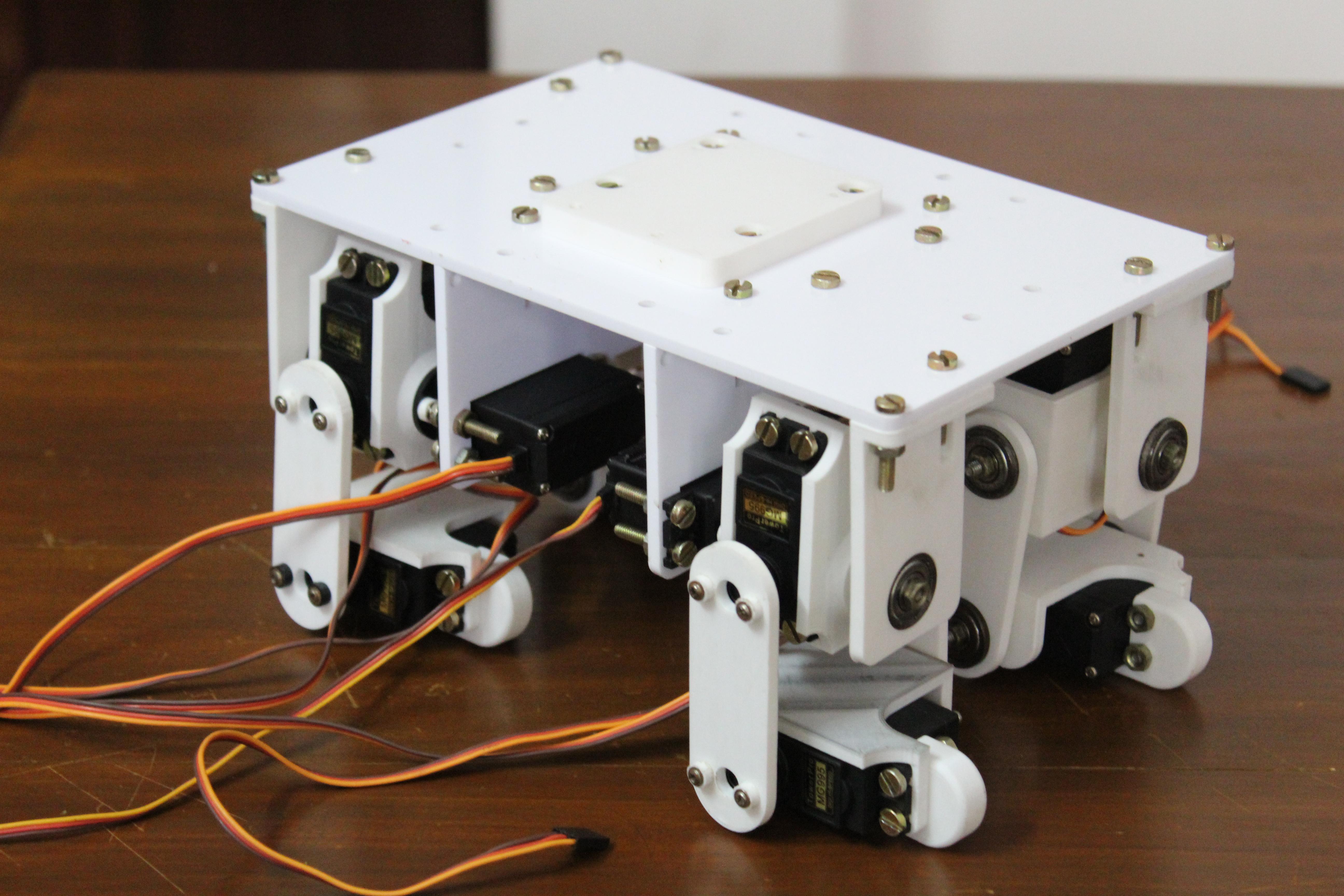
When the legs and torso are assembled, the robot can be assembled. Secure the legs to the four servomotors using the angle brackets attached to the femoral servomotor bracket. Finally, use bearing holders to support the opposite axle on the thigh bracket. Thread the axle through the bearing and secure with a nut. Attach the bearing holders to the top panel with screws and nuts.
The four-legged robot is ready.
Step 9: wires and electronics
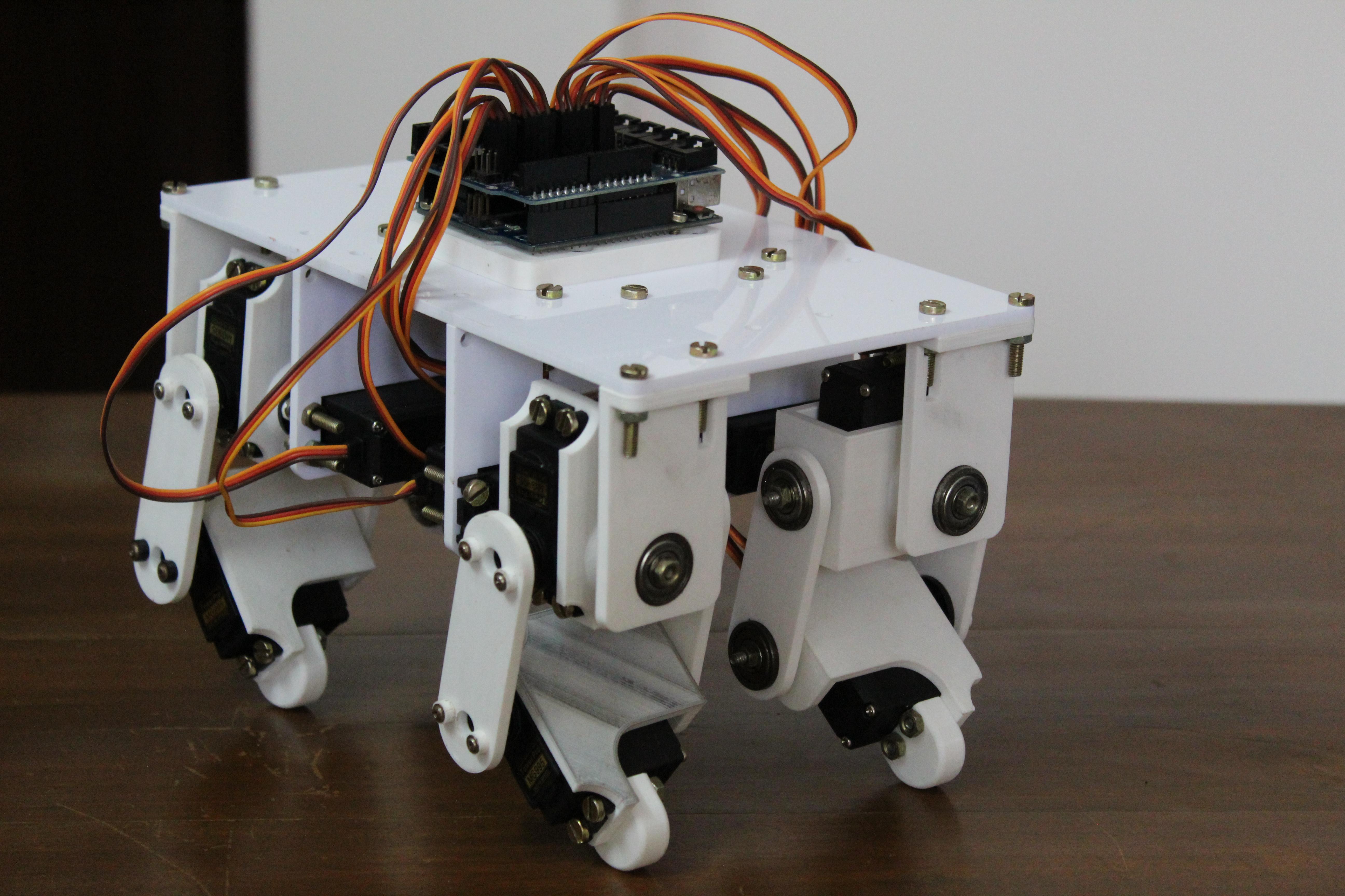
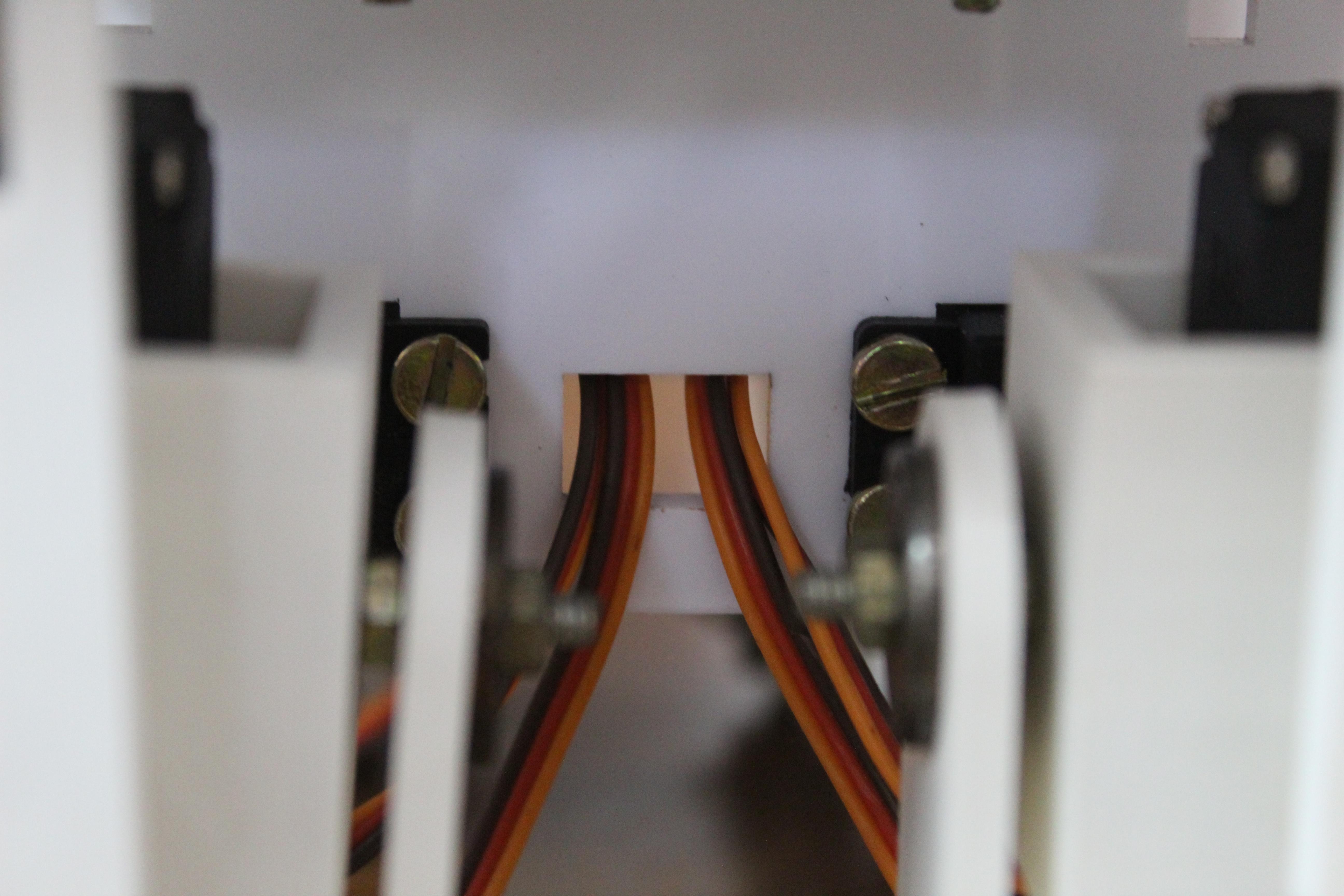
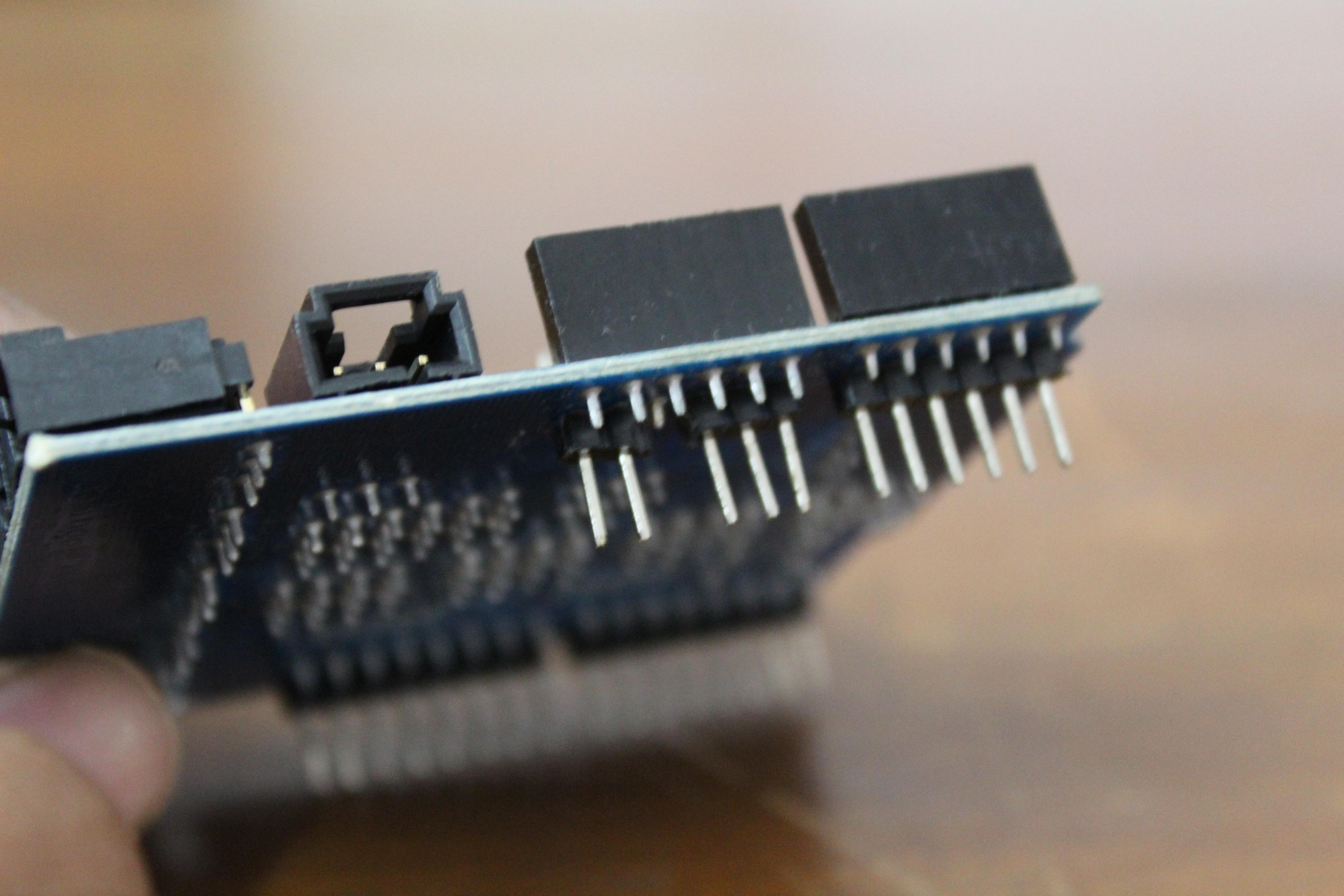
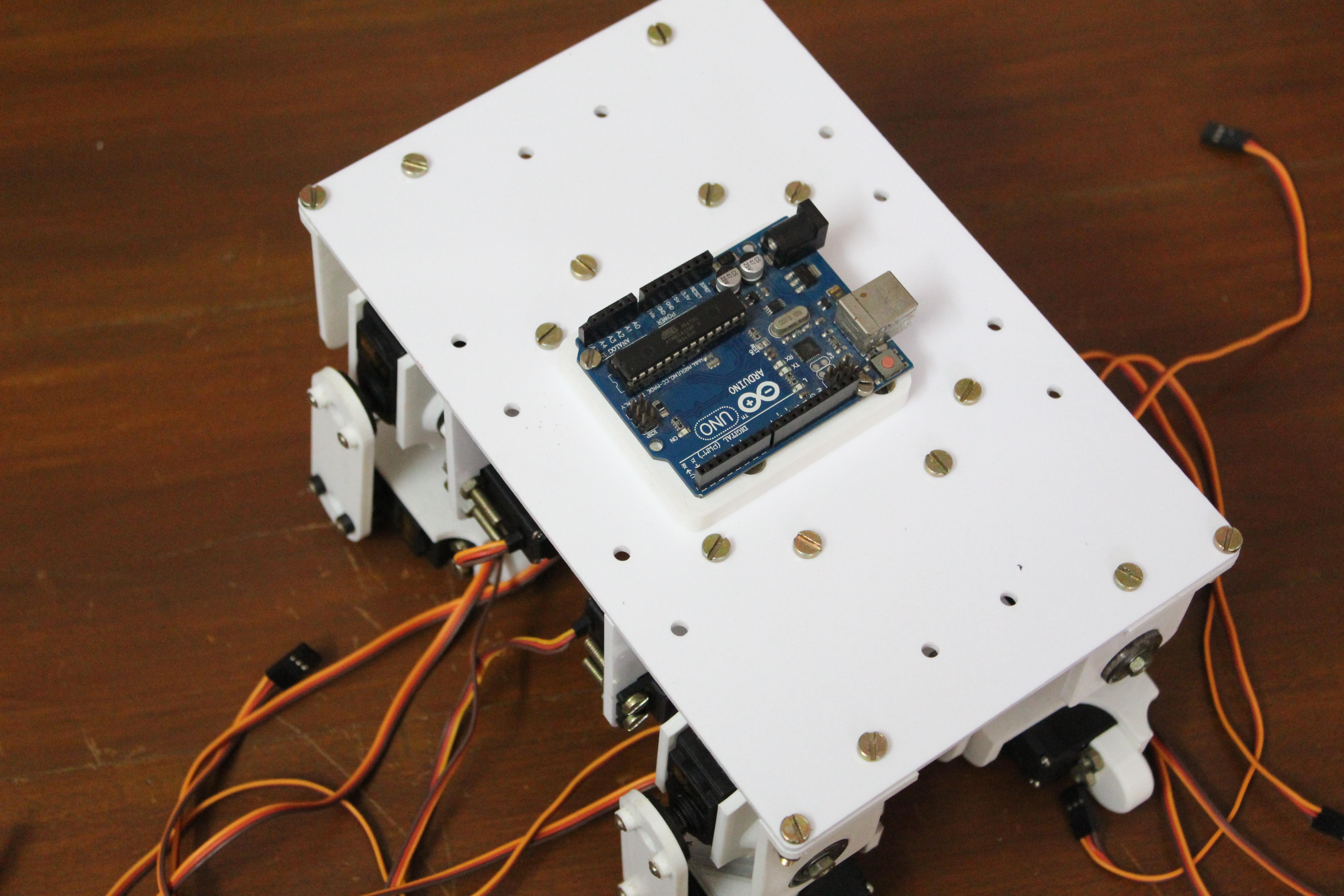
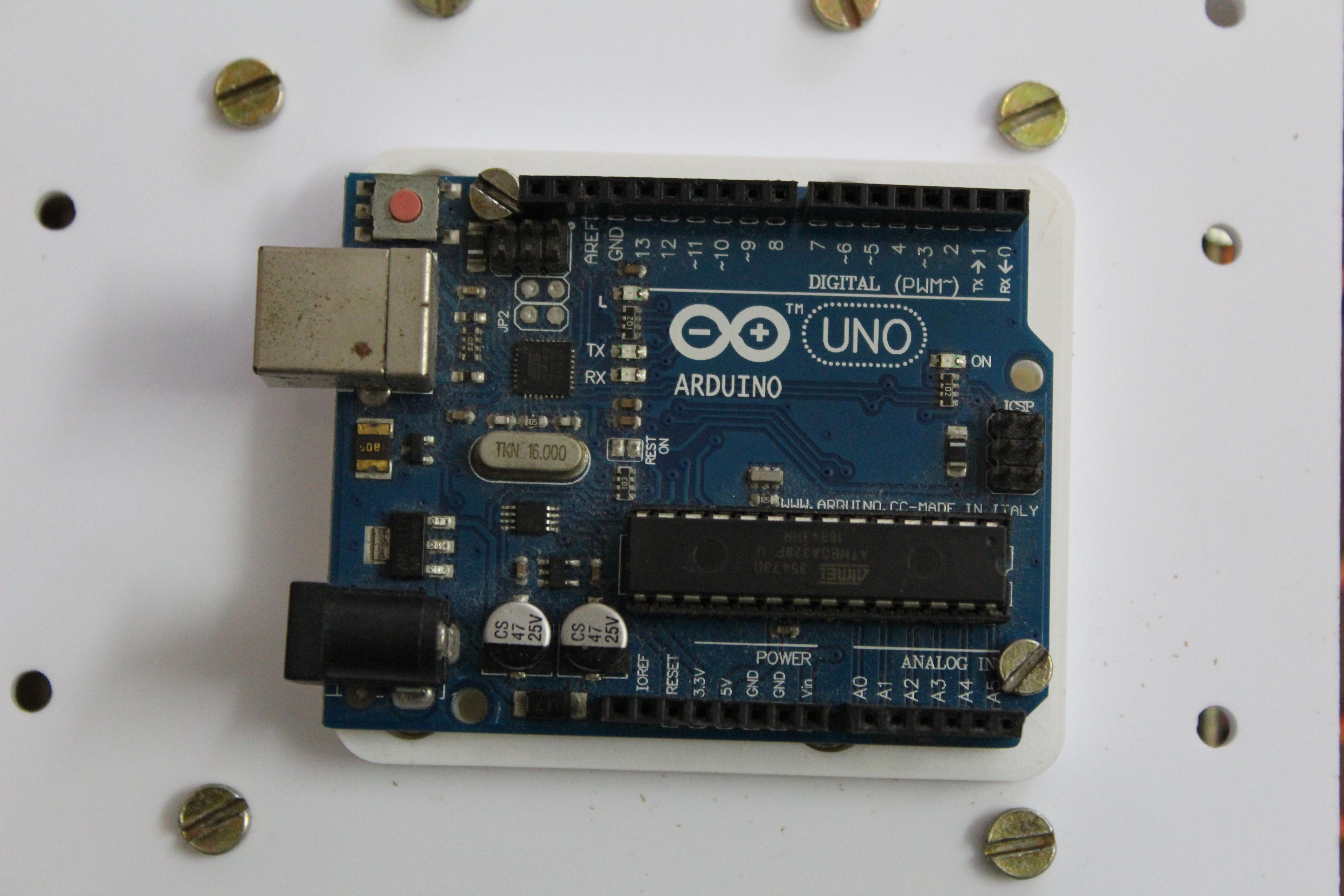
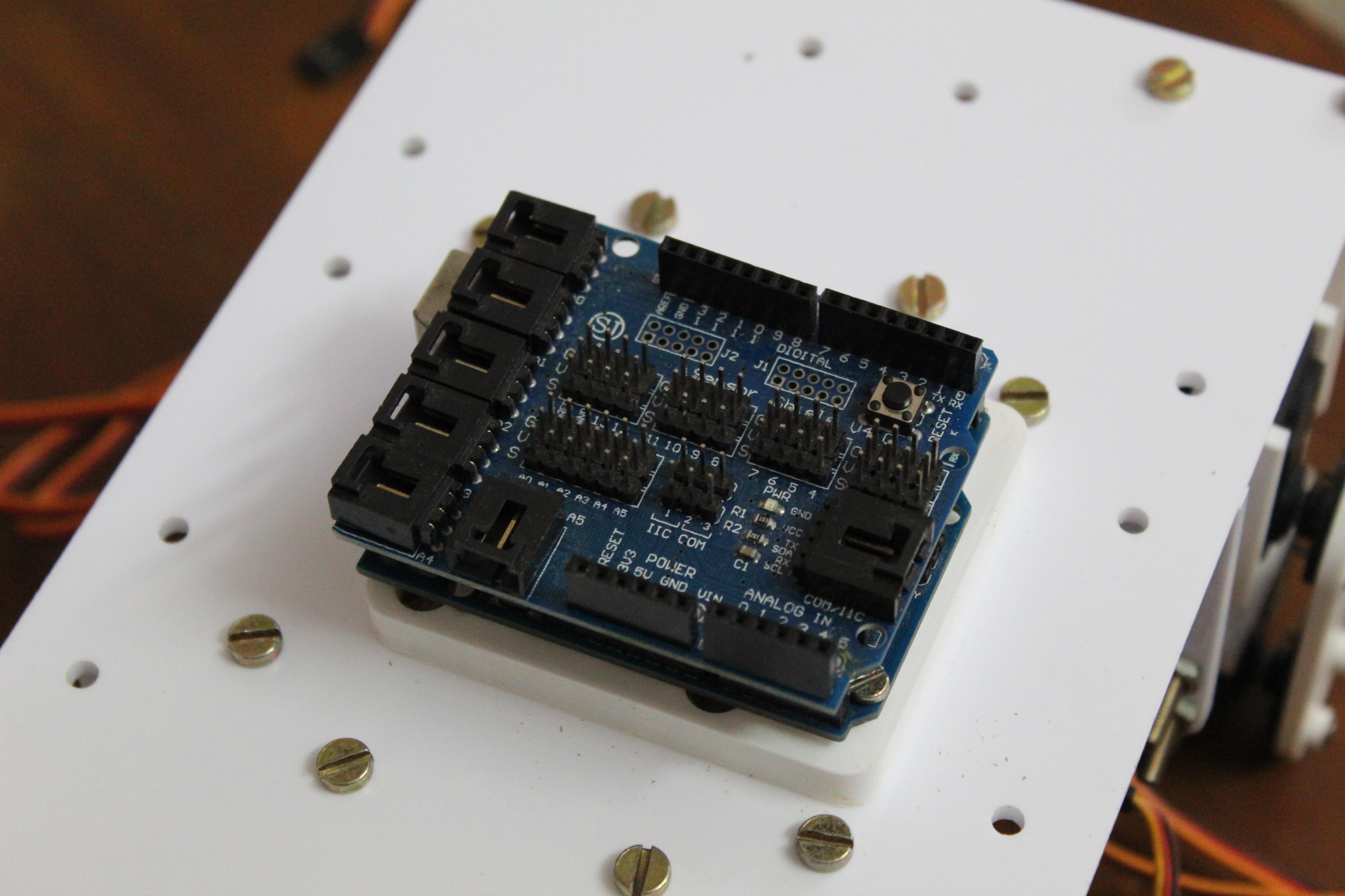
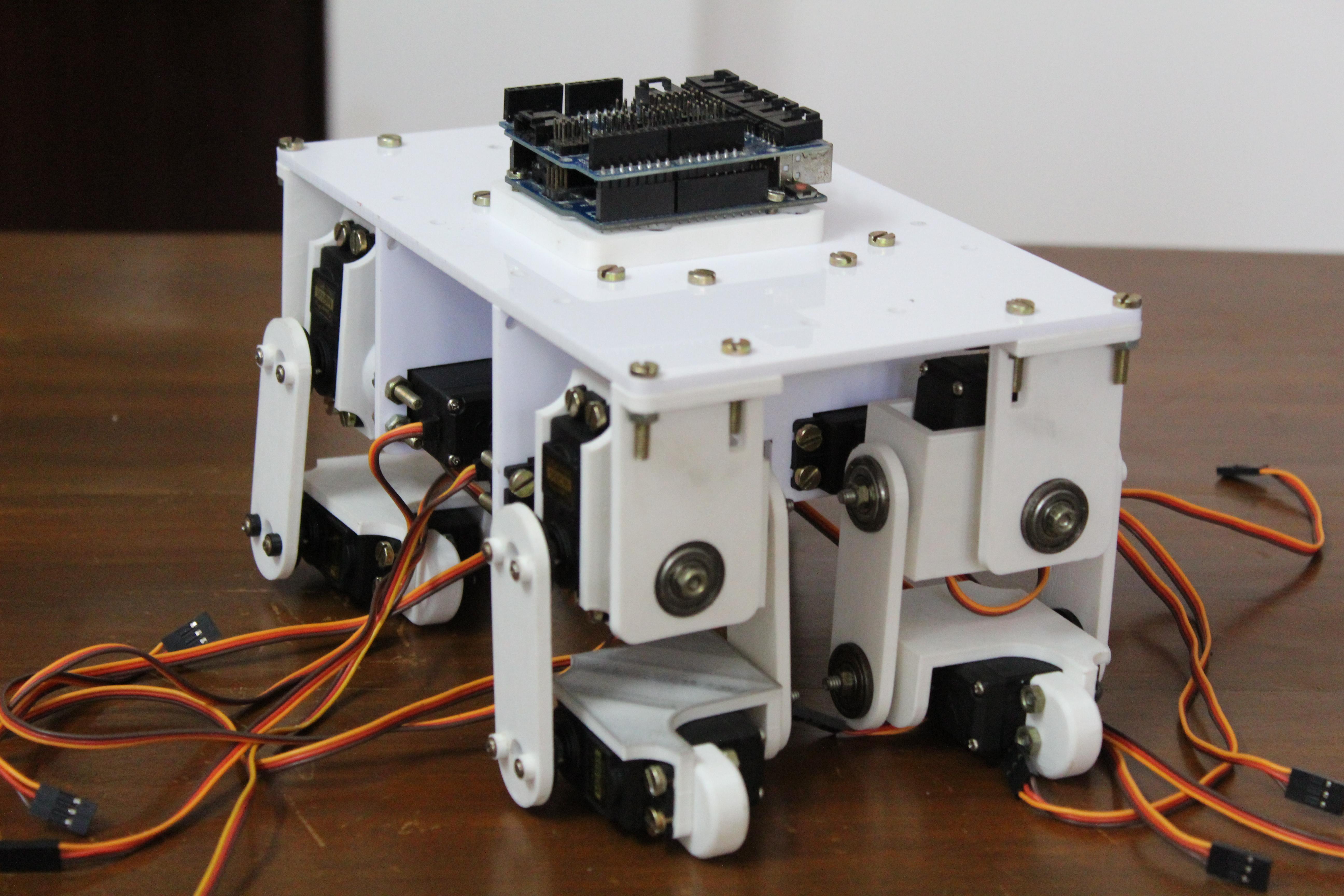
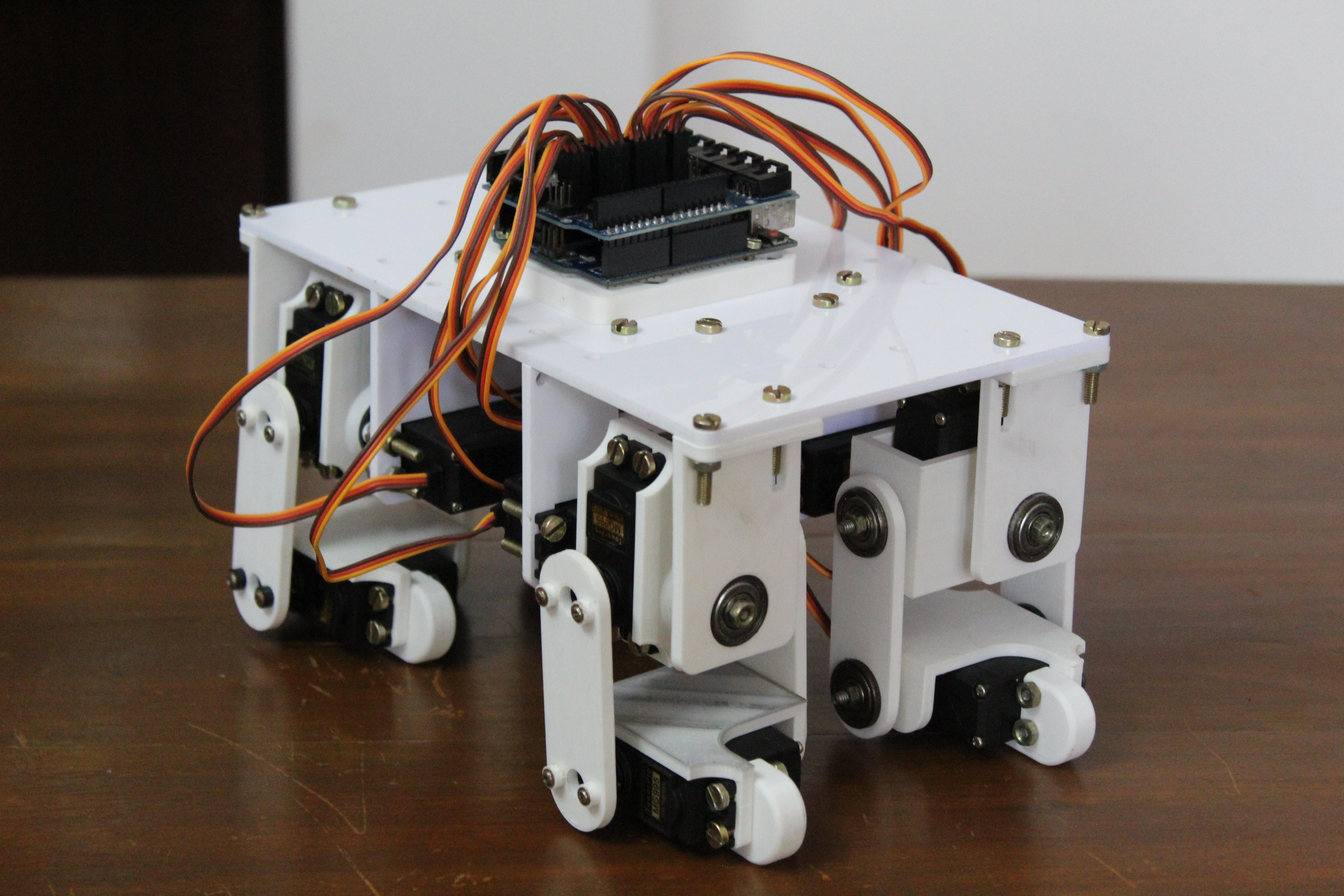
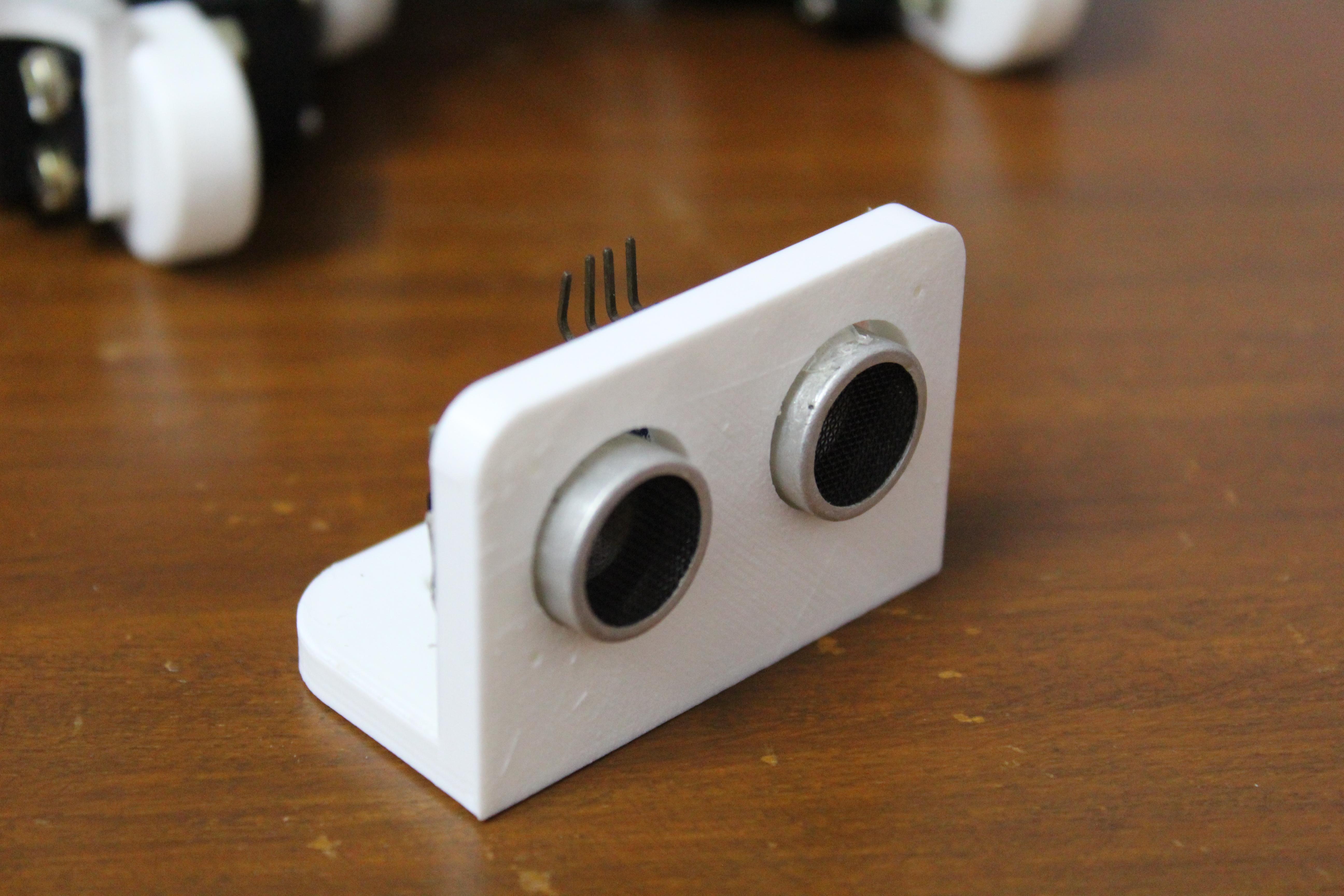
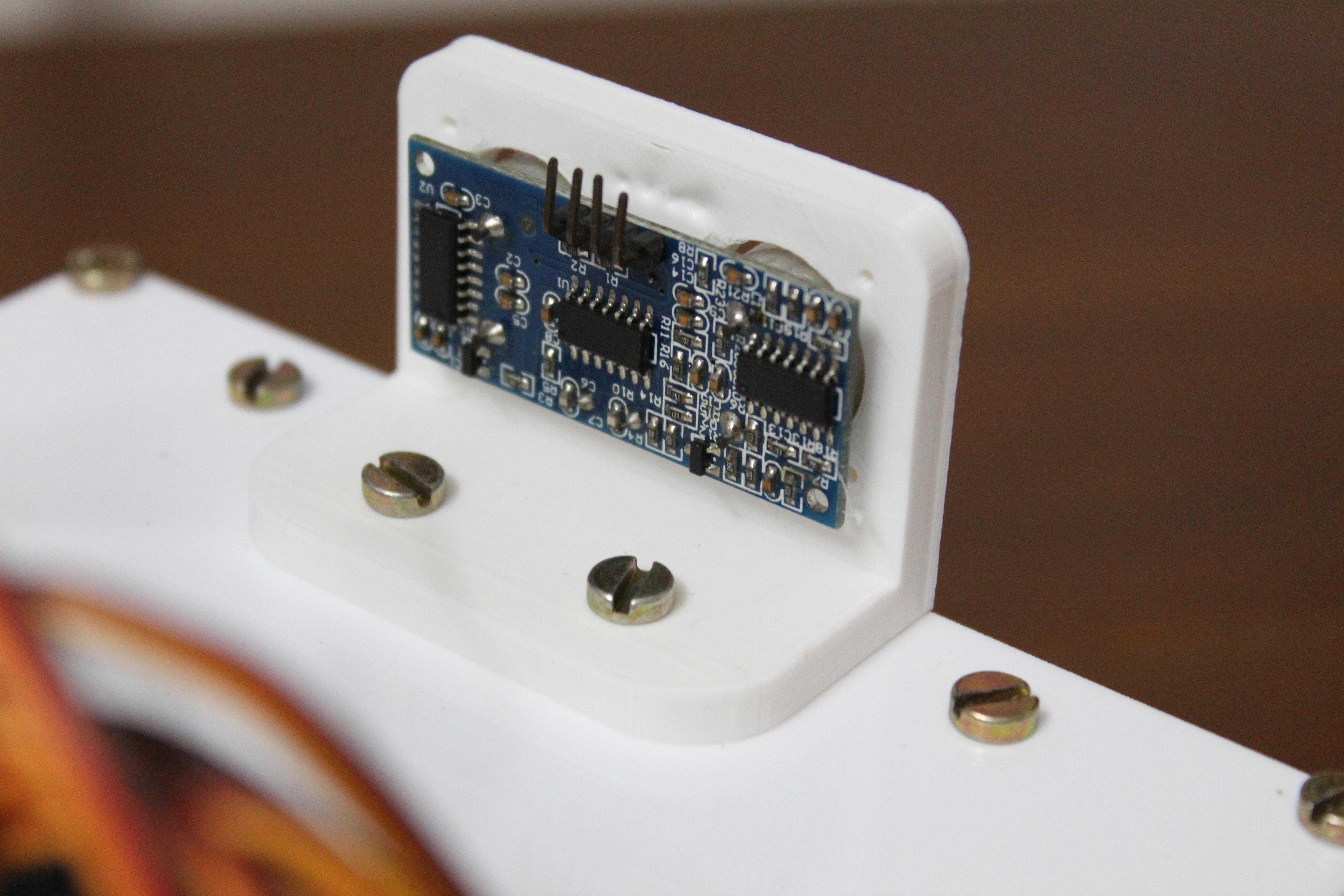
I decided to use an expansion board to connect the sensor shield, where there are contacts for the servo motors. I would recommend its 5th version - there is a separate connector for connecting an external power supply. But my board did not have this option. I studied it and realized that it draws 5V power from the Arduino board (when it comes to such powerful consumers as servo motors, this is a terrible idea that can damage the Arduino). I solved this problem by bending back the 5V pin so it doesn't connect to the Arduino power rail. This way you can give external power to the 5V pin without damaging the Arduino.
The following are the connections for the servomotors and the board contacts. Note: Hip1Servo are hip servo motors connected to the torso. Hip2Servo - hip servo motors connected to the leg. KneeServo - knee servo motors.
Leg 1 (front left):
Hip1Servo - 2
Hip2Servo - 3
KneeServo - 4
Leg 2 (front right):
Hip1Servo - 5
Hip2Servo - 6
KneeServo - 7
Leg 3 (rear left):
Hip1Servo - 8
Hip2Servo - 9
KneeServo - 10
foot 4 (rear right):
Hip1Servo - 11
Hip2Servo - 12
KneeServo - 13
Step 10: initial setup
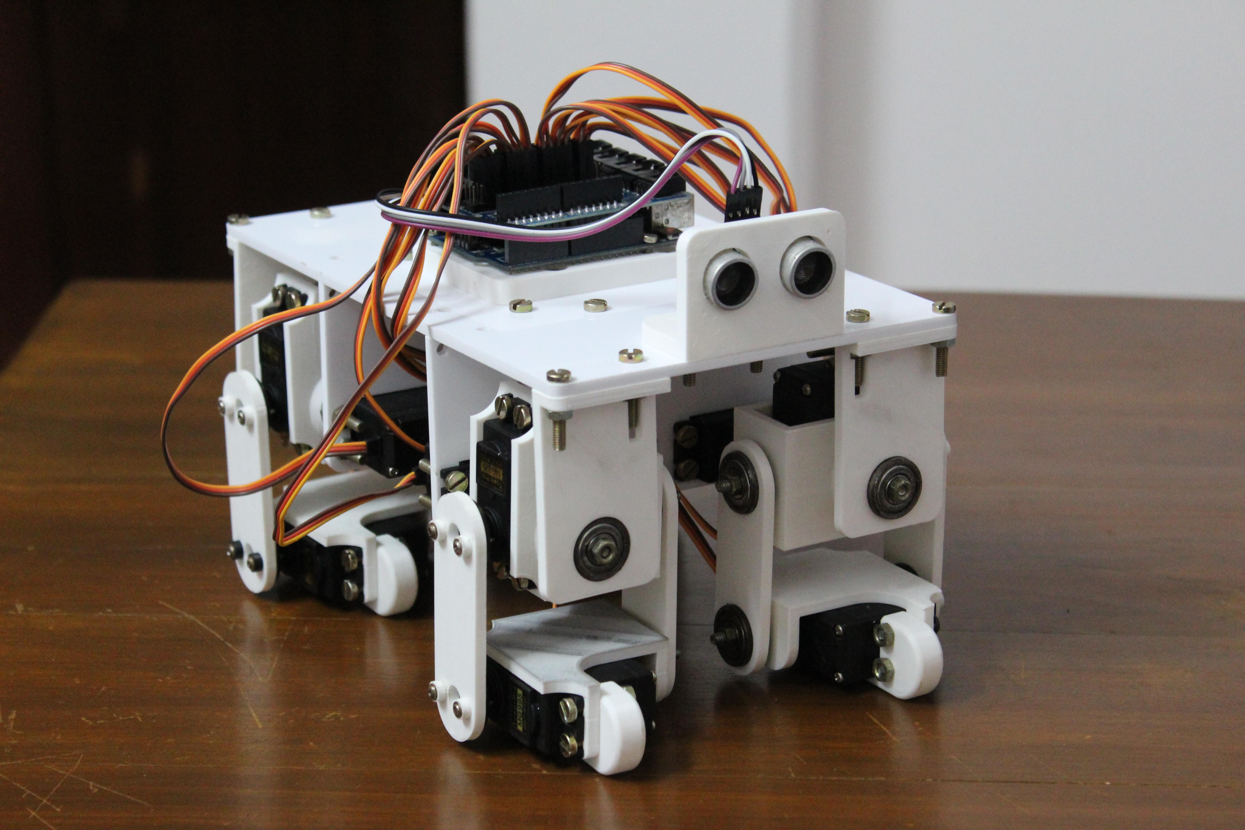
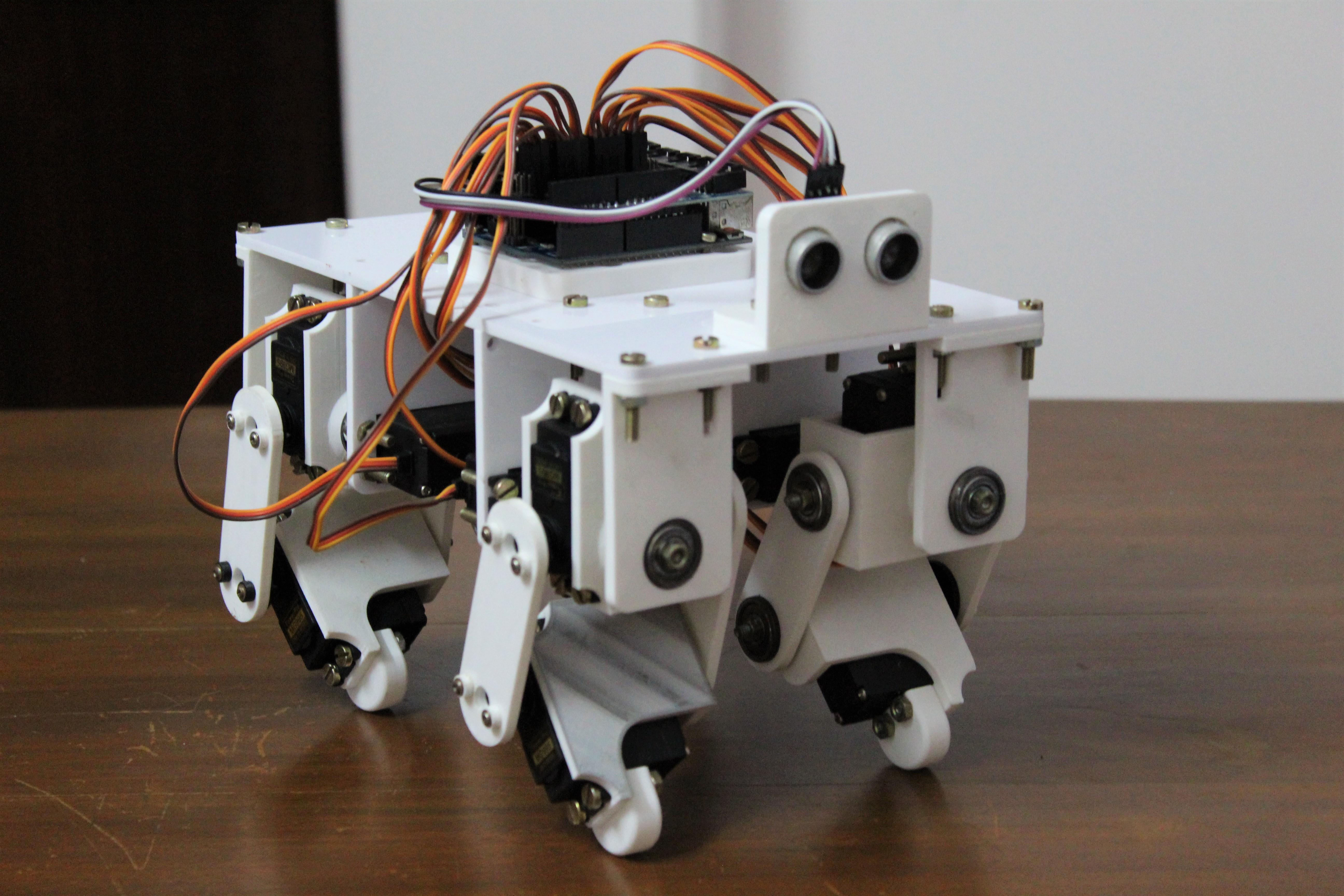
Before starting to program complex movements, it is necessary to set initial positions for each servo motor. They will give the robot a reference point from which to build different movements.
To avoid accidental damage to motors, you can first remove the corner brackets from the motors. Then upload the code to Arduino (link below). The code turns all servomotors to the 90 ° position. Then screw the brackets back so that all legs are perfectly level and the servomotors attached to the torso are perpendicular to the top panel.
Some joints may not be perfectly aligned. Then you will need to correct the values of the zeroPositions array located on the 4th line of the code. Each number represents the zero position of the corresponding servo motor (their order is the same as listed in the Arduino connection list). Play around with the values until your legs are perfectly straight.
For example, I got the following values:
int zeroPositions[12] = {93, 102, 85, 83, 90, 85, 92, 82, 85, 90, 85, 90};content.instructables.com/ORIG/F9K/WO73/KFZEKX13/F9KWO73KFZEKX13.ino
Step 11: a little about kinematics
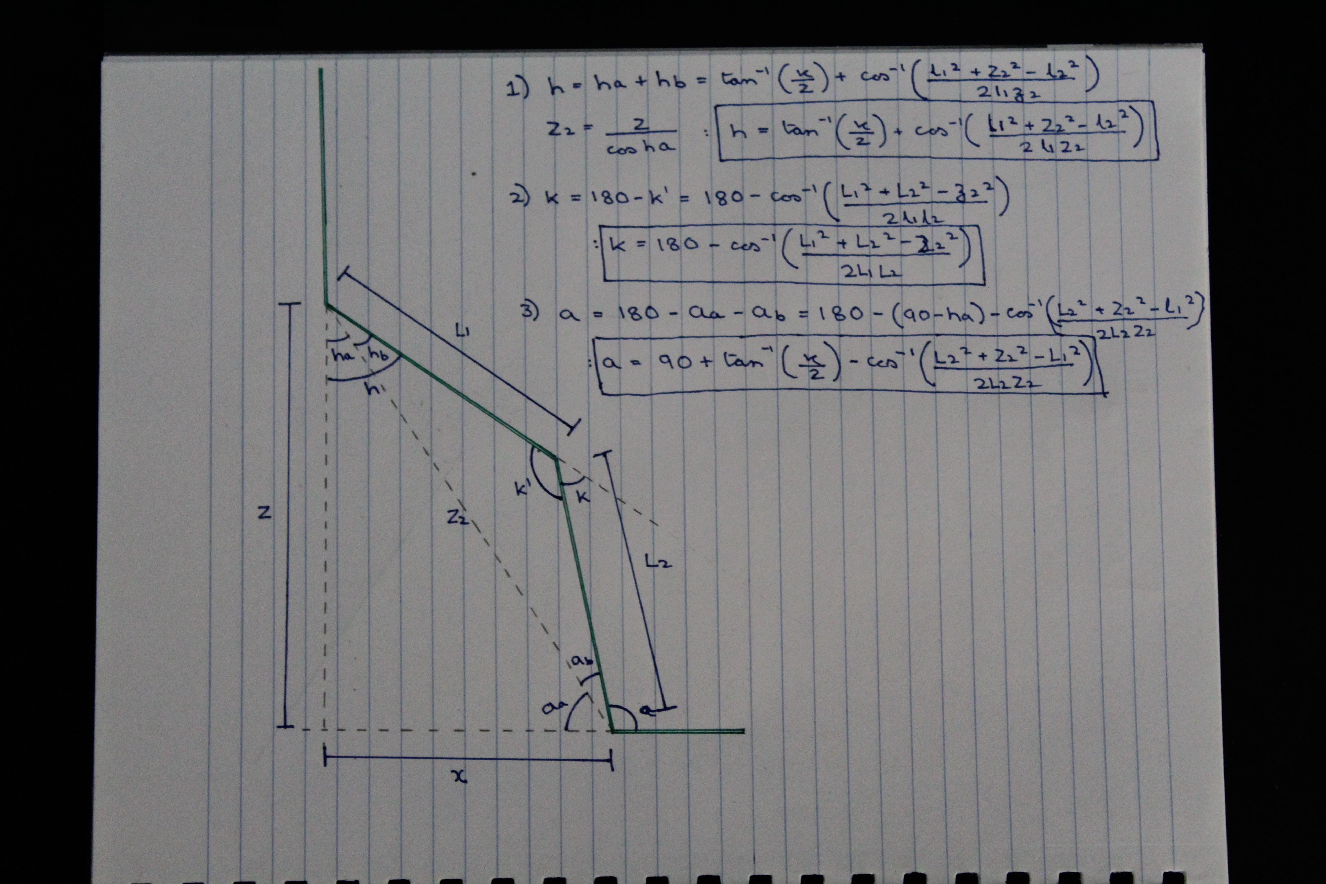
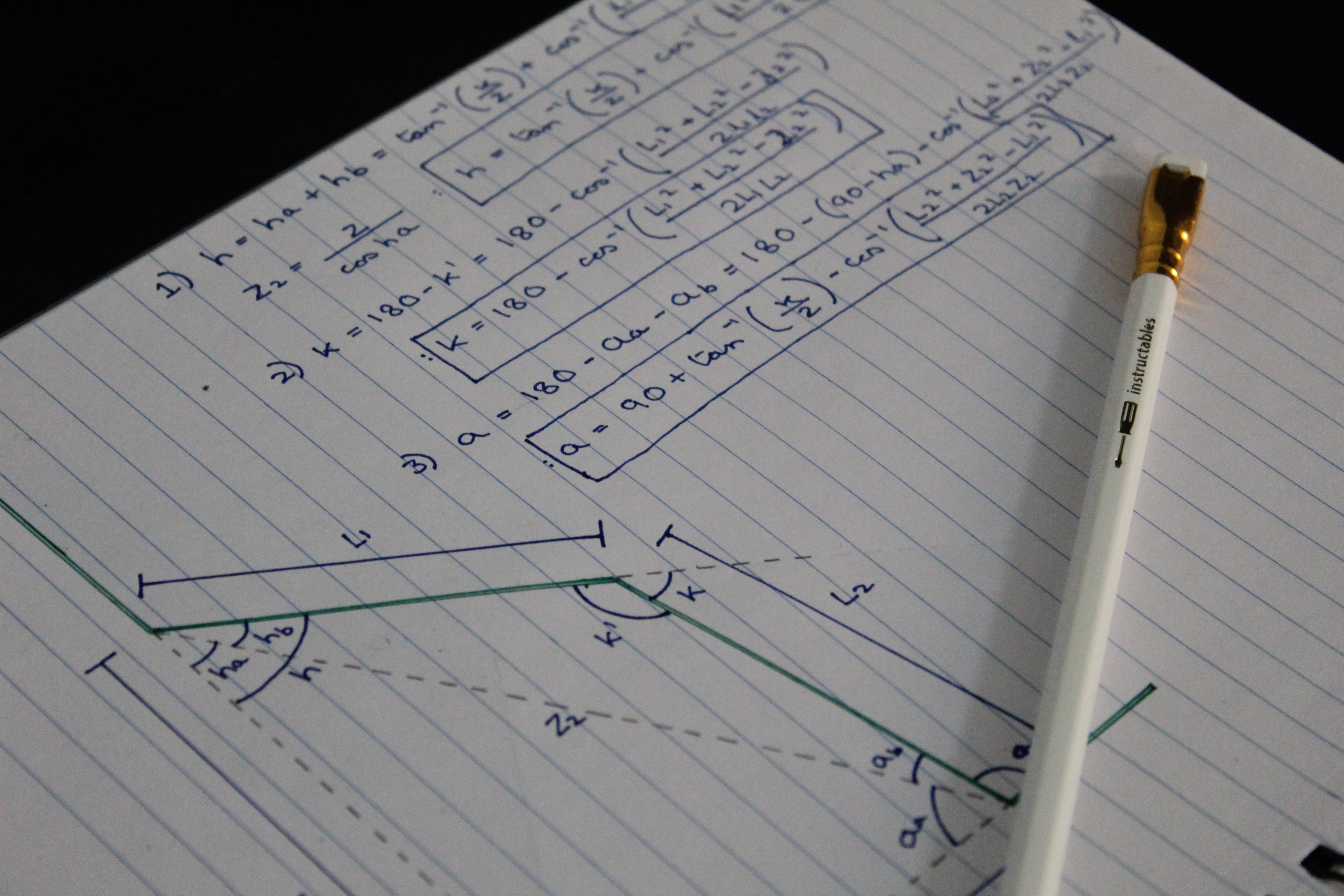

To force the robot to perform useful actions - walking, running and others - the trajectories of movement must be programmed for the servo motors. These are the trajectories along which the effector moves (in our case, the leg). This can be achieved in two ways:
- . , – .
- , . . , , . , , . . , , pos, , , , .
12:

Once you've finished connecting and initializing, you can start programming your robot and giving it cool trajectories to perform interesting tasks. In the code on the 4th line, change the values to those that you output in the initialization step. After uploading the code, the robot should start walking. If you notice that the directions of some joints are inverted, change the corresponding value in the array on line 5 (-1 to 1 and vice versa).
content.instructables.com/ORIG/FA6/3ZNJ/KFZEKX4Y/FA63ZNJKFZEKX4Y.ino
Step 13: summary and timing of experiments

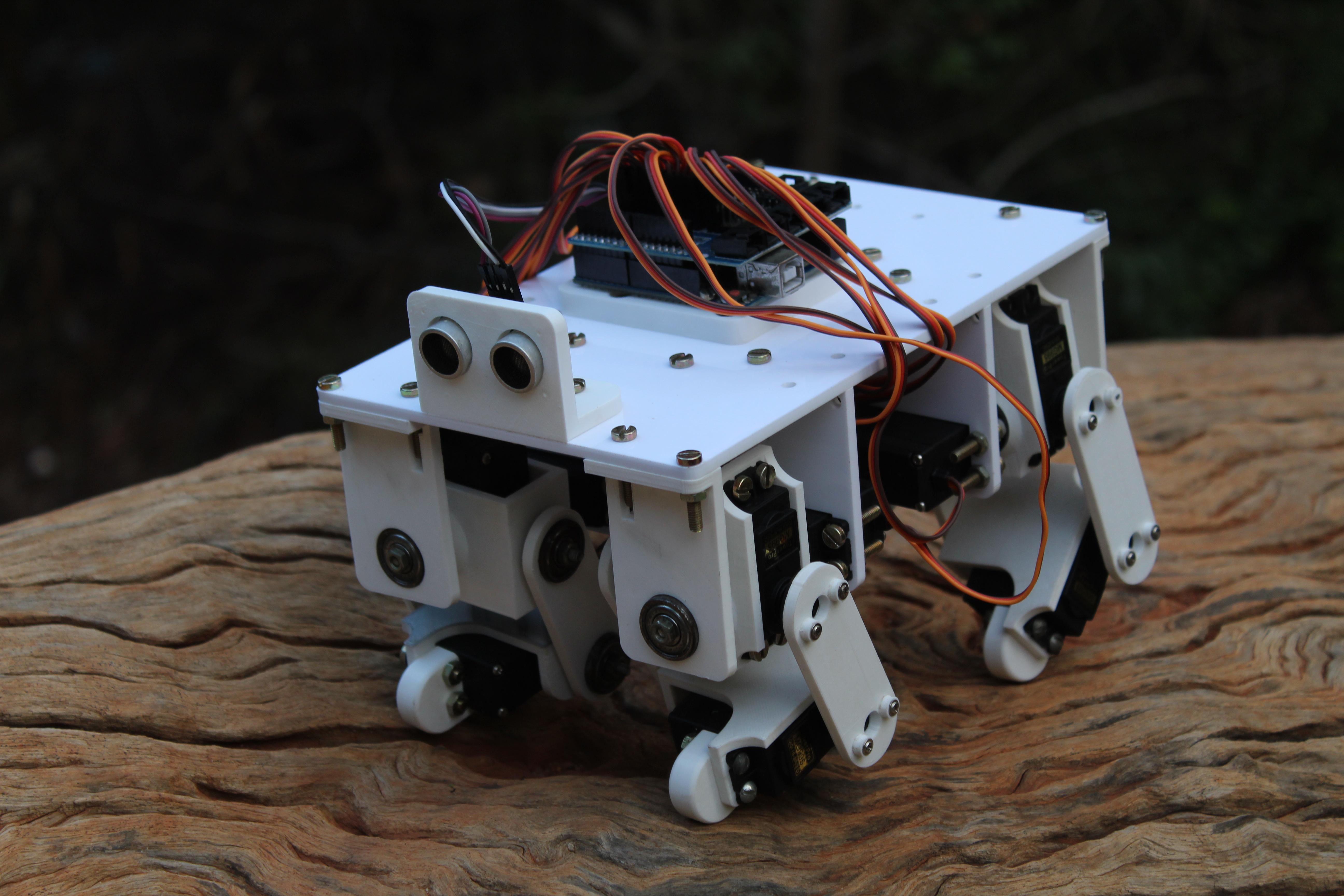
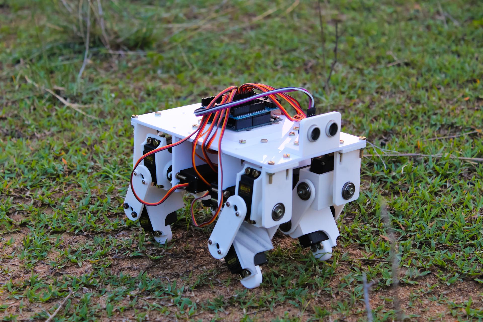
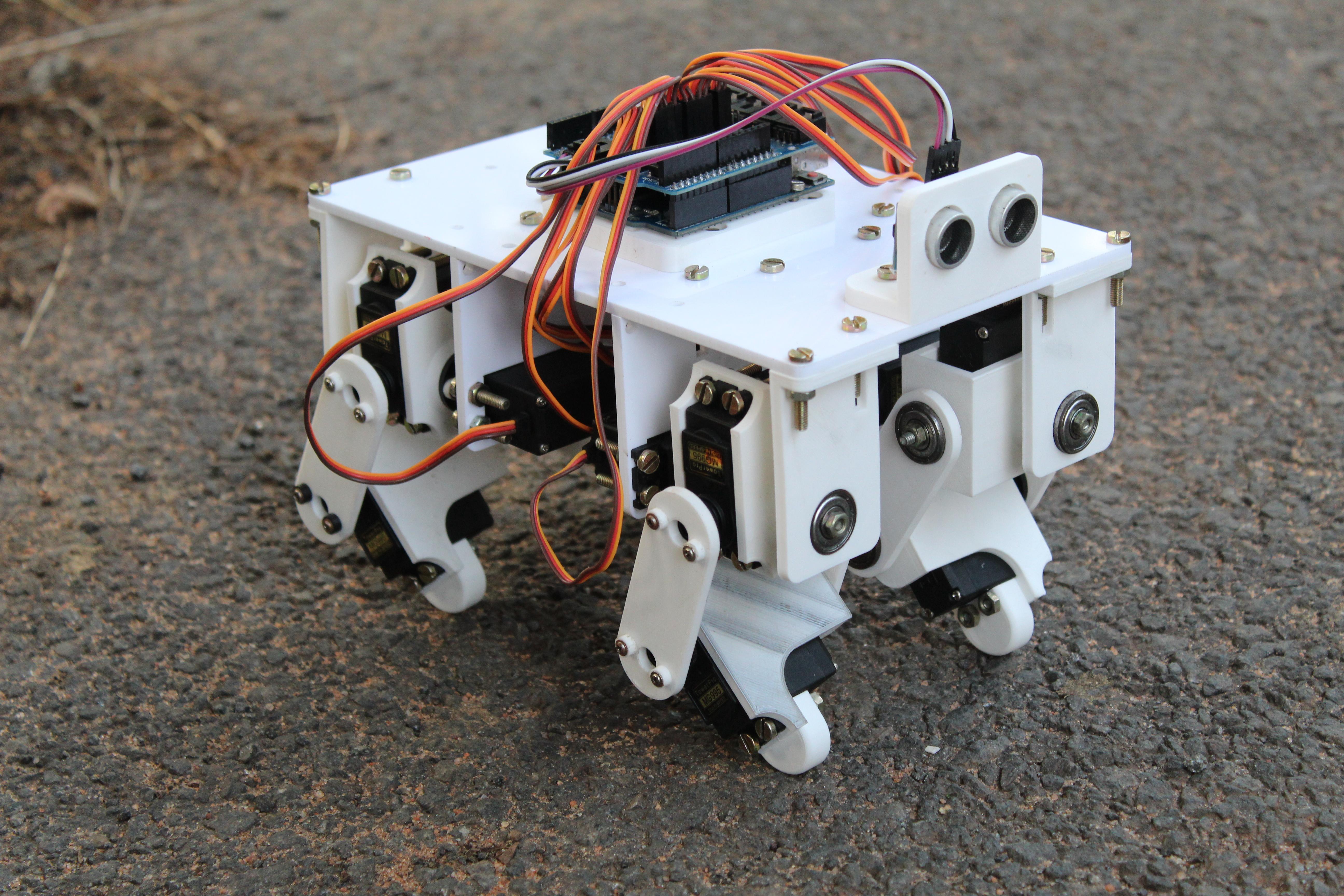
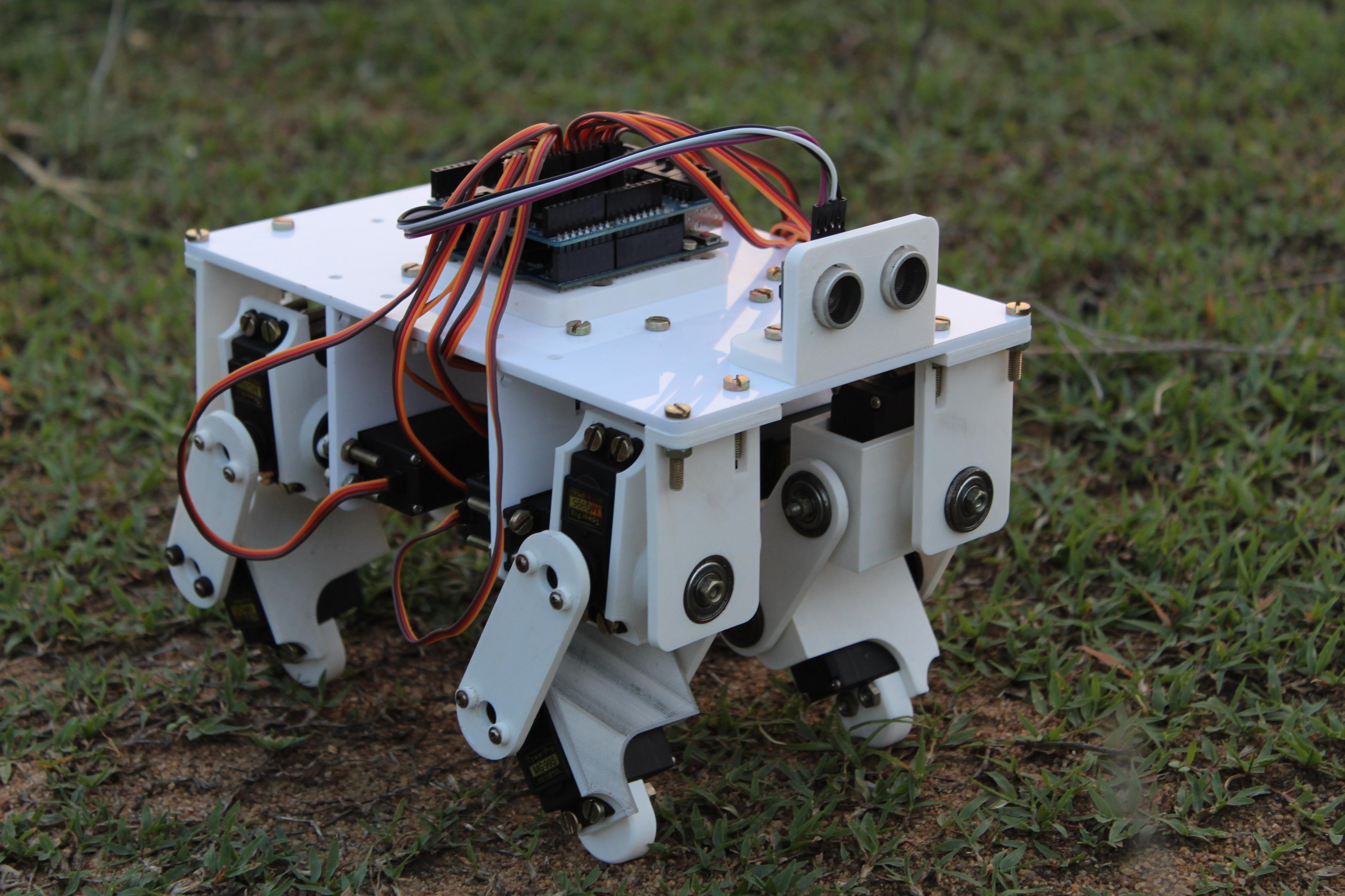
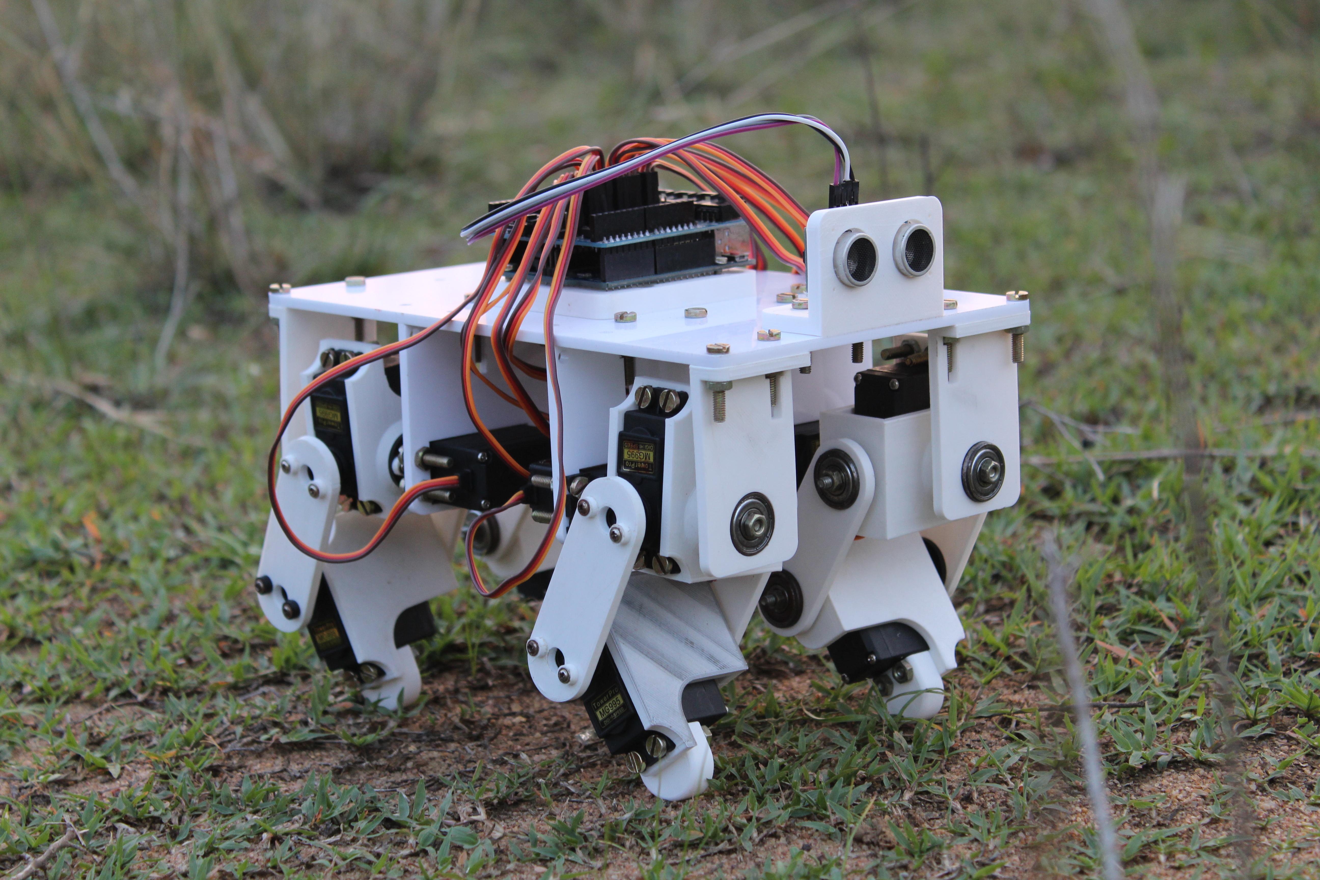
The robot can take steps from 2 to 5 cm long. Walking speed also varies. The robot makes a reliable platform for experimenting with gaits and other things such as jumping or performing complex tasks. I recommend changing the trajectories of movement, experiencing different gaits, watching how they affect the work of the robot. I have provided various mounts on the upper torso so that sensors such as a rangefinder or an inertial sensor can be attached there. You can try to fix some grip there.