This video shows: the Raspberry Pi3 board, to it, via the GPIO connector, the Mars Rover2rpi FPGA board (Cyclone IV) is connected to which an HDMI monitor is connected. The second monitor is connected via the standard HDMI Raspberry Pi3 connector. Everything together works like a system with two monitors.
I will tell you how this is done further.
The popular Raspberry Pi3 board has a GPIO connector through which you can connect different expansion boards: sensors, LEDs, stepper motor drivers, and more. The specific function of each pin on a connector depends on the port configuration. The ALT2 GPIO configuration allows you to switch the connector to the DPI interface mode, Display Parallel Interface. There are expansion cards for connecting VGA monitors via DPI. However, firstly, VGA monitors are no longer as common as HDMI, and secondly, the digital interface is getting better than analog. Moreover, the DAC on similar VGA expansion cards is usually made in the form of R-2-R chains and often no more than 6 bits per color.
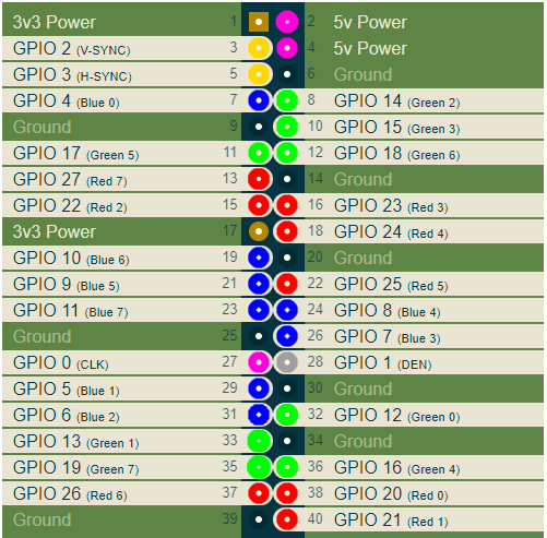
In ALT2 mode, the GPIO pins have the following meaning:

Here I colored the RGB pins of the connector in red, green and blue, respectively. Other important signals are V-SYNC and H-SYNC sweep sync signals, as well as CLK. The CLK clock is the frequency at which the pixel values are output to the connector, it depends on the selected video mode.
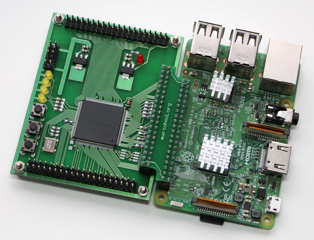
To connect a digital HDMI monitor, you need to capture DPI signals and convert them to HDMI signals. This can be done, for example, using some kind of FPGA board. As it turned out, the Mars rover2rpi board is suitable for these purposes. In truth, the main option for connecting this board through a special adapter looks like this:

This board serves to increase the number of GPIO ports and to connect more peripherals to the raspberry. At the same time, 4 GPIO signals with this connection are used for JTAG signals, so that the program from the raspberry can load the FPGA firmware into the FPGA. Because of this, such a standard connection does not suit me, 4 DPI signals drop out. Fortunately, the additional combs on the board have a Raspberry-compatible pinout. So that I can rotate the board 90 degrees and still connect it to my raspberry:

Of course, I have to use an external JTAG programmer, but this is not a problem.
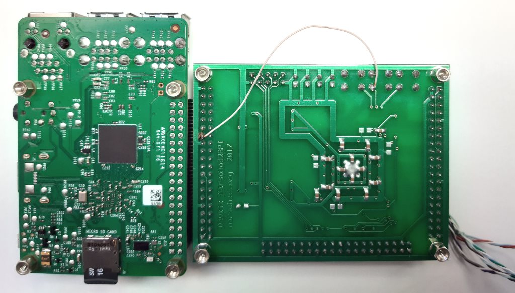
There is still a small problem. Not every FPGA pin can be used as a clock input. There are only a few dedicated pins that can be used for this purpose. So it turned out here that the GPIO_0 CLK signal does not go to the FPGA input, which can be used as the FPGA clock frequency input. So all the same I had to throw one wire on the scarf. I connect GPIO_0 and the KEY [1] signal of the board:

Now I will tell you a little about the project in the FPGA. The main difficulty in forming HDMI signals is very high frequencies. If you look at the pinout of the HDMI connector, you can see that the RGB signals are now serial differential signals:

Using a differential signal allows you to combat common mode noise on the transmission line. Thus, the original eight-bit code of each color signal is converted into 10-bit TMDS (Transition-minimized differential signaling). This is a special coding technique to remove the DC component from the signal and minimize signal switching on the differential line. Since one byte of color now needs to transmit 10 bits over the serial transmission line, it turns out that the clock frequency of the serializer should be 10 times higher than the clock frequency of the pixels. If we take, for example, the video mode 1280x720 60Hz, then the pixel frequency of this mode is 74.25 MHz. The serializer should have 742.5MHz.
Unfortunately, conventional FPGAs are not capable of this. However, fortunately for us, the FPGA has built-in DDIO pins. These are conclusions that are already kind of 2-to-1 serializers. That is, they can output two consecutive bits on the rising and falling edges of the clock frequency. This means that in the FPGA project, you can use not 740MHz, but 370MHz, but you need to use the DDIO output elements in the FPGA. Here 370 MHz is already quite attainable frequency. Unfortunately, the 1280x720 mode is the limit. Higher resolution in our FPGA Cyclone IV installed on the Mars rover 2rpi board cannot be achieved.
So, in the project, the input pixel frequency CLK goes to the PLL, where it is multiplied by 5. At this frequency, the bytes R, G, B are converted into pairs of bits. This is done by the TMDS encoder. The source code for Verilog HDL looks like this:
module hdmi(
	input wire pixclk,		// 74MHz
	input wire clk_TMDS2,	// 370MHz
	input wire hsync,
	input wire vsync,
	input wire active,
	input wire [7:0]red,
	input wire [7:0]green,
	input wire [7:0]blue,
	output wire TMDS_bh,
	output wire TMDS_bl,
	output wire TMDS_gh,
	output wire TMDS_gl,
	output wire TMDS_rh,
	output wire TMDS_rl
);

wire [9:0] TMDS_red, TMDS_green, TMDS_blue;
TMDS_encoder encode_R(.clk(pixclk), .VD(red  ), .CD({vsync,hsync}), .VDE(active), .TMDS(TMDS_red));
TMDS_encoder encode_G(.clk(pixclk), .VD(green), .CD({vsync,hsync}), .VDE(active), .TMDS(TMDS_green));
TMDS_encoder encode_B(.clk(pixclk), .VD(blue ), .CD({vsync,hsync}), .VDE(active), .TMDS(TMDS_blue));

reg [2:0] TMDS_mod5=0;  // modulus 5 counter
reg [4:0] TMDS_shift_bh=0, TMDS_shift_bl=0;
reg [4:0] TMDS_shift_gh=0, TMDS_shift_gl=0;
reg [4:0] TMDS_shift_rh=0, TMDS_shift_rl=0;

wire [4:0] TMDS_blue_l  = {TMDS_blue[9],TMDS_blue[7],TMDS_blue[5],TMDS_blue[3],TMDS_blue[1]};
wire [4:0] TMDS_blue_h  = {TMDS_blue[8],TMDS_blue[6],TMDS_blue[4],TMDS_blue[2],TMDS_blue[0]};
wire [4:0] TMDS_green_l = {TMDS_green[9],TMDS_green[7],TMDS_green[5],TMDS_green[3],TMDS_green[1]};
wire [4:0] TMDS_green_h = {TMDS_green[8],TMDS_green[6],TMDS_green[4],TMDS_green[2],TMDS_green[0]};
wire [4:0] TMDS_red_l   = {TMDS_red[9],TMDS_red[7],TMDS_red[5],TMDS_red[3],TMDS_red[1]};
wire [4:0] TMDS_red_h   = {TMDS_red[8],TMDS_red[6],TMDS_red[4],TMDS_red[2],TMDS_red[0]};

always @(posedge clk_TMDS2)
begin
	TMDS_shift_bh <= TMDS_mod5[2] ? TMDS_blue_h  : TMDS_shift_bh  [4:1];
	TMDS_shift_bl <= TMDS_mod5[2] ? TMDS_blue_l  : TMDS_shift_bl  [4:1];
	TMDS_shift_gh <= TMDS_mod5[2] ? TMDS_green_h : TMDS_shift_gh  [4:1];
	TMDS_shift_gl <= TMDS_mod5[2] ? TMDS_green_l : TMDS_shift_gl  [4:1];
	TMDS_shift_rh <= TMDS_mod5[2] ? TMDS_red_h   : TMDS_shift_rh  [4:1];
	TMDS_shift_rl <= TMDS_mod5[2] ? TMDS_red_l   : TMDS_shift_rl  [4:1];
	TMDS_mod5 <= (TMDS_mod5[2]) ? 3'd0 : TMDS_mod5+3'd1;
end

assign TMDS_bh = TMDS_shift_bh[0];
assign TMDS_bl = TMDS_shift_bl[0];
assign TMDS_gh = TMDS_shift_gh[0];
assign TMDS_gl = TMDS_shift_gl[0];
assign TMDS_rh = TMDS_shift_rh[0];
assign TMDS_rl = TMDS_shift_rl[0];

endmodule

module TMDS_encoder(
	input clk,
	input [7:0] VD,	// video data (red, green or blue)
	input [1:0] CD,	// control data
	input VDE,  	// video data enable, to choose between CD (when VDE=0) and VD (when VDE=1)
	output reg [9:0] TMDS = 0
);

wire [3:0] Nb1s = VD[0] + VD[1] + VD[2] + VD[3] + VD[4] + VD[5] + VD[6] + VD[7];
wire XNOR = (Nb1s>4'd4) || (Nb1s==4'd4 && VD[0]==1'b0);
wire [8:0] q_m = {~XNOR, q_m[6:0] ^ VD[7:1] ^ {7{XNOR}}, VD[0]};

reg [3:0] balance_acc = 0;
wire [3:0] balance = q_m[0] + q_m[1] + q_m[2] + q_m[3] + q_m[4] + q_m[5] + q_m[6] + q_m[7] - 4'd4;
wire balance_sign_eq = (balance[3] == balance_acc[3]);
wire invert_q_m = (balance==0 || balance_acc==0) ? ~q_m[8] : balance_sign_eq;
wire [3:0] balance_acc_inc = balance - ({q_m[8] ^ ~balance_sign_eq} & ~(balance==0 || balance_acc==0));
wire [3:0] balance_acc_new = invert_q_m ? balance_acc-balance_acc_inc : balance_acc+balance_acc_inc;
wire [9:0] TMDS_data = {invert_q_m, q_m[8], q_m[7:0] ^ {8{invert_q_m}}};
wire [9:0] TMDS_code = CD[1] ? (CD[0] ? 10'b1010101011 : 10'b0101010100) : (CD[0] ? 10'b0010101011 : 10'b1101010100);

always @(posedge clk) TMDS <= VDE ? TMDS_data : TMDS_code;
always @(posedge clk) balance_acc <= VDE ? balance_acc_new : 4'h0;

endmodule
Then the output pairs are fed to the DDIO output, which sequentially issues a one-bit signal on the rising and falling edges.
DDIO itself could be described with such Verilog code:
module ddio(
	input wire d0,
	input wire d1,
	input wire clk,
	output wire out
	);

reg r_d0;
reg r_d1;
always @(posedge clk)
begin
	r_d0 <= d0;
	r_d1 <= d1;
end
assign out = clk ? r_d0 : r_d1;
endmodule
But it probably won't work that way. You need to use the alter megafunction ALTDDIO_OUT to actually use the output DDIO elements. It is the ALTDDIO_OUT library component that is used in my project.
It may all look a little tricky, but it works.
You can view all the source code written in Verilog HDL here on github .
The compiled FPGA firmware is stitched into an EPCS chip installed on the Mars Rover2rpi board. Thus, when power is supplied to the FPGA board, the FPGA will initialize from flash memory and start.
Now we need to talk a little about the configuration of the Raspberry itself.
I am doing experiments on Raspberry PI OS (32 bit) based on Debian Buster, Version: August 2020,
Release date: 2020-08-20, Kernel version: 5.4.
There are two things to do:
- edit the config.txt file;
- create an X server configuration to work with two monitors.
When editing the /boot/config.txt file, you need to:
- disable the use of i2c, i2s, spi;
- enable DPI mode using the overlay dtoverlay = dpi24;
- set video mode 1280x720 60Hz, 24 bits per point per DPI;
- specify the required number of framebuffers 2 (max_framebuffers = 2, only then the second device / dev / fb1 will appear)
The full text of the config.txt file looks like this.
# For more options and information see
# http://rpf.io/configtxt
# Some settings may impact device functionality. See link above for details

# uncomment if you get no picture on HDMI for a default "safe" mode
#hdmi_safe=1

# uncomment this if your display has a black border of unused pixels visible
# and your display can output without overscan
disable_overscan=1

# uncomment the following to adjust overscan. Use positive numbers if console
# goes off screen, and negative if there is too much border
#overscan_left=16
#overscan_right=16
#overscan_top=16
#overscan_bottom=16

# uncomment to force a console size. By default it will be display's size minus
# overscan.
#framebuffer_width=1280
#framebuffer_height=720

# uncomment if hdmi display is not detected and composite is being output
hdmi_force_hotplug=1

# uncomment to force a specific HDMI mode (this will force VGA)
#hdmi_group=1
#hdmi_mode=1

# uncomment to force a HDMI mode rather than DVI. This can make audio work in
# DMT (computer monitor) modes
#hdmi_drive=2

# uncomment to increase signal to HDMI, if you have interference, blanking, or
# no display
#config_hdmi_boost=4

# uncomment for composite PAL
#sdtv_mode=2

#uncomment to overclock the arm. 700 MHz is the default.
#arm_freq=800

# Uncomment some or all of these to enable the optional hardware interfaces
#dtparam=i2c_arm=on
#dtparam=i2s=on
#dtparam=spi=on

dtparam=i2c_arm=off
dtparam=spi=off
dtparam=i2s=off

dtoverlay=dpi24
overscan_left=0
overscan_right=0
overscan_top=0
overscan_bottom=0
framebuffer_width=1280
framebuffer_height=720
display_default_lcd=0
enable_dpi_lcd=1
dpi_group=2
dpi_mode=87
#dpi_group=1
#dpi_mode=4
dpi_output_format=0x6f027
dpi_timings=1280 1 110 40 220 720 1 5 5 20 0 0 0 60 0 74000000 3

# Uncomment this to enable infrared communication.
#dtoverlay=gpio-ir,gpio_pin=17
#dtoverlay=gpio-ir-tx,gpio_pin=18

# Additional overlays and parameters are documented /boot/overlays/README

# Enable audio (loads snd_bcm2835)
dtparam=audio=on

[pi4]
# Enable DRM VC4 V3D driver on top of the dispmanx display stack
#dtoverlay=vc4-fkms-v3d
max_framebuffers=2

[all]
#dtoverlay=vc4-fkms-v3d
max_framebuffers=2
After that, you need to create a configuration file for the X server to use two monitors on two framebuffers / dev / fb0 and / dev / fb1:
My config file /usr/share/x11/xorg.conf.d/60-dualscreen.conf is like this
Section "Device"
        Identifier      "LCD"
        Driver          "fbturbo"
        Option          "fbdev" "/dev/fb0"
        Option          "ShadowFB" "off"
        Option          "SwapbuffersWait" "true"
EndSection

Section "Device"
        Identifier      "HDMI"
        Driver          "fbturbo"
        Option          "fbdev" "/dev/fb1"
        Option          "ShadowFB" "off"
        Option          "SwapbuffersWait" "true"
EndSection

Section "Monitor"
        Identifier      "LCD-monitor"
        Option          "Primary" "true"
EndSection

Section "Monitor"
        Identifier      "HDMI-monitor"
        Option          "RightOf" "LCD-monitor"
EndSection

Section "Screen"
        Identifier      "screen0"
        Device          "LCD"
        Monitor         "LCD-monitor"
EndSection

Section "Screen"
        Identifier      "screen1"
        Device          "HDMI"
	Monitor         "HDMI-monitor"
EndSection

Section "ServerLayout"
        Identifier      "default"
        Option          "Xinerama" "on"
        Option          "Clone" "off"
        Screen 0        "screen0"
        Screen 1        "screen1" RightOf "screen0"
EndSection
Well, if not already installed, then you need to install Xinerama. Then the desktop space will be fully expanded to two monitors, as shown above in the demo video.
That's probably all. Now, Raspberry Pi3 owners will be able to use two monitors.
The description and diagram of the Mars rover2rpi board can be viewed here .