
CAD (computer-aided design system) is, in the simplest case, a program for the development and execution of project documentation (drawings). And in order for drawings from different authors (designers) to be equally readable and understood by production workers and other specialists, there are GOSTs for design, which many of us studied at school (stamps, fonts, letter tilt, etc.). But each person is individual, and when developing documentation, he often proceeds from his own sense of "readability" and "beautiful": in one place he will deviate from the standard, then in another he will put shading a little differently. As a result, the drawings, collected in one volume (set), begin to differ from each other, albeit slightly, but differ. How to bring all documents to the same style? It would seem that the software will help with this, but in fact there are some subtleties here.We invite you to study the topic in detail.
Introduction
Each CAD system, focusing on universal use, provides the ability to customize for user tasks: you can load your own fonts, customize line types and thickness, add your own hatches, dimension styles, etc. Is it a blessing or a blessing in the power of customization of CAD tools? On the one hand, of course, it's great when the functionality of a software product is able to ensure the implementation of copyright engineering ideas, when it is possible to set up a comfortable workplace for yourself.
On the other hand, if more than one person is involved in a project, there is a risk - and quite a big one - of encountering insurmountable problems at the stage of consolidated registration and regulatory control. In addition to individual characteristics, specialists are different in skills, specifics of work, and length of work experience. And in the end, instead of the successful delivery of the project, we receive it for revision with the indication “Does not meet the design standards”. A frantic adjustment to the uniformity of the drawing settings and the program itself begins, integration with external printing devices ... And so ten times in a row - from project to project, for different customers who also have their own requirements for documentation. Deadlines are violated, quality falls ...
Awareness
Gradually, companies come to understand that information from general, universal GOSTs for registration may not be enough, that it is necessary to develop an enterprise's own standard for working in CAD, sharpened for its design specifics and software and hardware infrastructure. CAD managers are emerging in organizations who, based on work experience, define the “rules of the game”, customize their workplaces, and then distribute this customization to colleagues' computers. And finally, either the official or the unofficial "Enterprise Standard for the Development, Maintenance and Execution of Electronic Project Documentation" ("STF on EPD", which is also called "STF on DWG" if * .dwg-like CAD is used) is being implemented.
What is usually included in STP on DWG? If we talk about the nanoCAD platform, then, as a rule, the following settings are included in the standard:
- DWT- – *.dwg-, (/), , , , , , ( -, , ..);
- SHX- – , *.dwg-, ;
- PAT- – , *.dwg-;
- , , . , , ..
In addition, experienced CAD managers in STP on * .dwg can select third-party LISP scripts useful for the company (or even develop their own); create toolbars, which will display block catalogs, pre-configured tools and the same automation scripts; configure PC3 files, as well as CTB and STB plot styles, which allow you to output drawings to a specific plotter with specific settings in one click.
Settings can be general for everyone or individual for each department. And you can also develop and connect DWS standards, which in real time control the compliance of the current * .dwg file with the DWT template presets and notify about deviations from the standard (Fig. 1) ...

Fig. 1. An example of checking a * .dwg file according to the DWS standard in nanoCAD 20
In general, right now there is a wide range of possibilities for adapting nanoCAD right out of the box for your company's infrastructure. You just need to set up and start using. What's the problem?
Problematic
The problem is that CAD managers manage such settings only when these settings are distributed to colleagues' workstations (usually at the time of CAD installation). What will happen to the "Standard" further - the designers must control. And, as experience shows, in the process of work, the settings gradually go astray. Why? We remember that each designer has his own level of knowledge in CAD. And there are developments in the * .dwg format that do not correspond to the new standard, and users do not know how to reconfigure them. In addition, you have to deal with third-party * .dwg, which confuse settings when copied to a user's document. Finally, it may be necessary to include new settings in the "STP": hatching, fonts, formats for a new project ...
Now imagine that in your organization, 100 people work in CAD for eight hours every day and can change the settings of both the program and the drawings used every second - moreover, they themselves do not always understand that they have changed these settings. "Standard" floats, chaos returns ...
Of course, there is an alternative way to distribute settings: through shared folders. But this method makes users dependent on a local network connection. And it does not provide protection against users overriding settings.
Therefore, a new approach is clearly needed.
Can this be automated?
In fact, you need a tool that receives settings and automatically infuses them into workplaces. This will allow developing, distributing and dynamically updating the "Enterprise Standard", controlling its changes in the process of designers' work. And how can this problem be solved, except by means of the * .dwg platform itself?
Realizing this, the nanoCAD developers started to create a specialized mechanism that works at a basic level. The general idea is for the CAD manager to collect all the settings that make up "STP to DWG", and then distribute them to workstations in one click. Any update is a reconfiguration and update from the designers, again in one click. The idea was implemented for three years and appeared in January 2020 with the release of the nanoCAD Plus 20 platform. The implementation of the idea was the "Corporate Governance" module. Let's see how it works.
How it works?
All semantic units that ensure the operation of nanoCAD in accordance with enterprise standards can be divided into three basic sections (Fig. 2):
- CAD manager workstation where settings files are generated;
- – , ;
- , .

Figure: 2. General scheme of work of the "Corporate Governance" module on the nanoCAD Plus 20 and higher platform
The first thing that needs to be done for the Corporate module to work is to choose a central location for storing and updating settings. The best option is to select a folder that can be accessed via FTP. This way of organizing the repository will hide the file structure, which means it will block the leak of the organization's intellectual property, even theoretically eliminating the possibility of copying the "Enterprise Standard" outside.
Information about the settings storage is automatically transferred to user workstations from the Nanosoft license server - that is why the Corporate Governance module works only with a network license.
Then it is the turn of the CAD manager, who sets up the lists of user groups with the indication of incoming accounts. What is a group? This is any logical distribution of users. In the simplest case, all STP users can be represented in one group. You can also, for example, divide users into project departments of the organization, or form groups of participants in projects that the company is working on. That is why one user account can be a member of several groups at once, and it is possible to dynamically switch between settings as you connect to new projects with different STP settings.
Next, the CAD manager generates settings for each group (Fig. 3):
- « », , nanoCAD *.dwg. :
*.dwg (*.dws),
(*.pat),
(*.pc3),
(*.stb *.ctb),
(*.shx),
*.dwg- (*.dwt),
(*.ntc); - : , (*.xml) (*.cfg), , (, , ), , ..;
- design system settings files, that is, settings for platform annotation elements (PARAMS command): parameters of dimensions, leaders, autoscaling styles, etc.
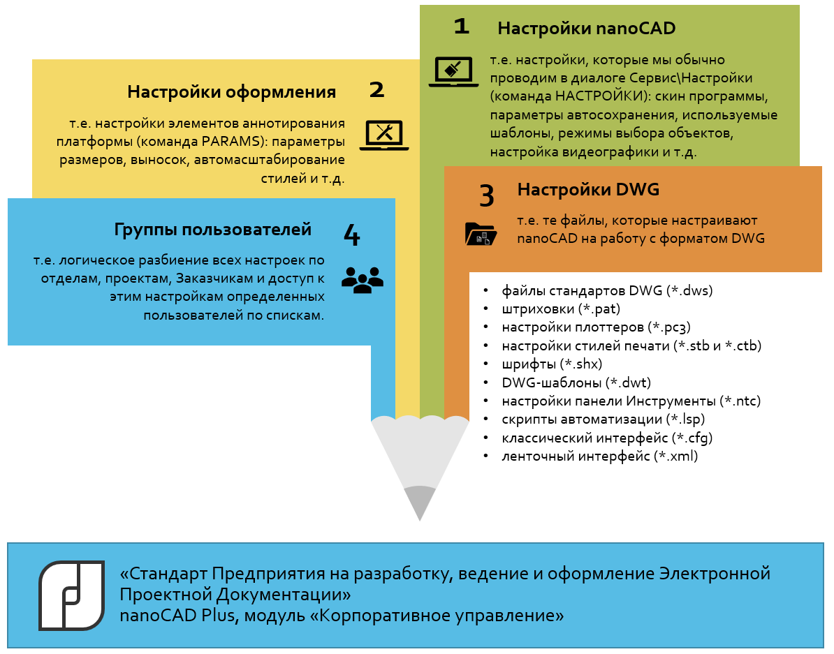
Figure: 3. The structure of the "Enterprise Standard", controlled through the "Corporate Governance" module in nanoCAD Plus 20 and higher
In addition, the CAD manager can control the style of updating the settings at the user's workstations. There are three options:
- "Soft" style: settings come to users' workplaces, complementing those that users have customized for themselves. Allowed to make changes;
- "Medium" style: the settings that come to the users' workplace can be expanded (add your own styles, font files, hatches, print styles, etc.). You will not be able to make changes - different settings files will be updated in accordance with the reference files sent by the administrator;
- "Hard" style: the user can neither expand the settings, nor make changes - they will all be brought in line with the distributed reference kit.
When the groups and settings for them are specified, we actually form a version of the "Enterprise Standard for work in * .dwg" and are ready to distribute it to workplaces. To do this, the CAD manager publishes the standard to the centralized repository defined in the first step. And, in principle, that's all - the settings will automatically go to user workstations the next time nanoCAD Plus is loaded.
What's the bottom line?
As a result, we get an organized system for managing CAD settings. When nanoCAD 20 is opened on the license server, the user is identified and all the necessary settings are automatically copied to the local computer (Fig. 4). Each time the software product is opened, an update will take place - without user intervention: everything is configured by the CAD manager, he also allows the application.
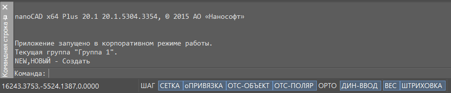
Figure: 4. In nanoCAD Plus with the "Corporate Governance" module, the settings of the "Enterprise Standard for the development, maintenance and registration of * .dwg" come to users' workplaces automatically. The
specialist is busy in several projects at once and, accordingly, is included in several groups? When starting nanoCAD, you will be able to choose a configuration.
Does the specifics of the work imply business trips? You can configure work from an external network. If there is no Internet connection, nanoCAD will simply start working with the last saved configuration.
In other words, the developers of the "Corporate Governance" module tried to take into account all the peculiarities of organizing work on the release of the project.
Summing up, let's list the practical benefits of implementing the module point by point:
- ease of use for the user: just run nanoCAD 20, and all settings will happen automatically;
- dynamics of making changes to the STF: the CAD manager made changes, published them - and the settings immediately appeared for the user;
- control from one workplace: all settings are collected at one point;
- : , ;
- : ;
- : FTP ( «» );
- : , « ».
We invite you to share your successes, ask questions and leave your wishes on our forum at forum.nanocad.ru .
Olga Kutuzova,
Head of
Software Implementation Projects at
Nanosoft JSC
Denis Ozhigin,
Technical Director
at Nanosoft Development LLC