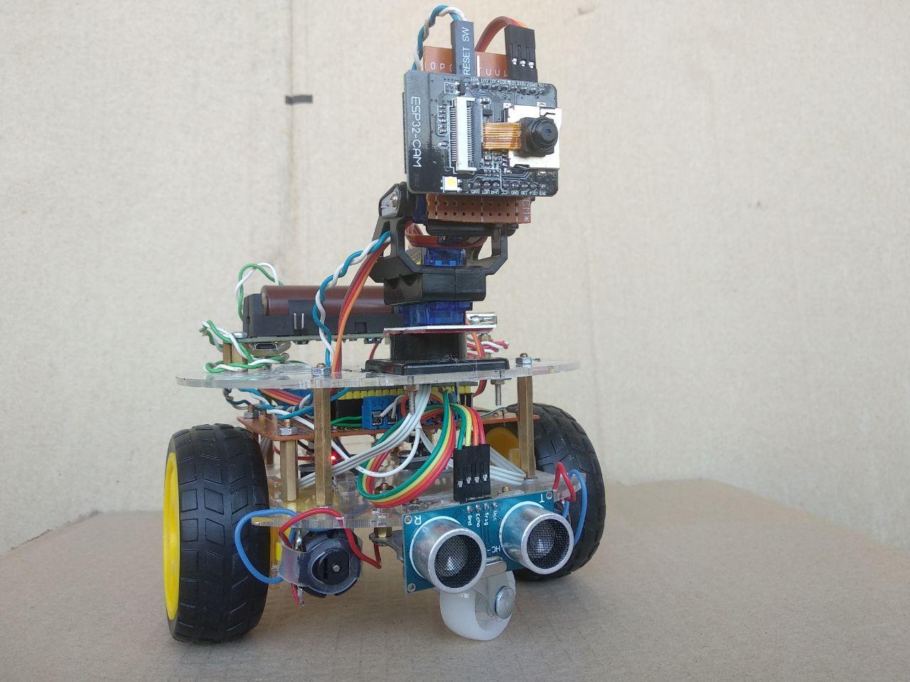
The assembled structure looks like this
Components
The base is a mobile two-deck robo-platform Car Chassis 2WD Mini Kit

Platform dimensions: 135 mm x 135 mm x 80 mm The
drive is two standard motor-wheels with a gearbox and a DC motor with raster disks for speed sensors:
- rated current: 250mA max. at a voltage of 3.6 V
- torque 800 g / cm (at 6V voltage)
- supply voltage: 6 - 8 V
- no-load speed: 170 rpm (at 3.6 V)
- gear ratio: 1: 48
- axles come out on both sides
- axle diameter: 5 mm
- dimensions: 64x20x20 mm
- weight: 26g
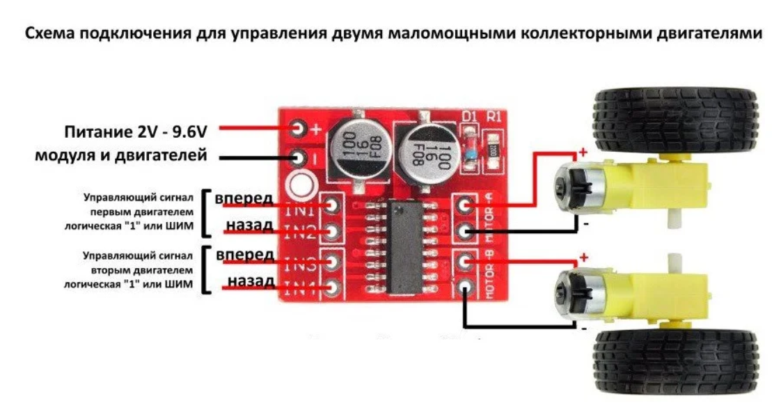
The MX1508 module was selected as the motor driver.You
can read about the module here
Technical parameters:
- Supply voltage: 2 - 10 V
- Working driver per channel: 1.5 A (peak current 2.5 A, no more than 10 seconds)
- Logic input: 5V
- Dimensions: 24.7 x 21 x 0.5mm
For the horizontal and vertical movement of the IP camera, the popular SG90 2kg servo motors have been selected.The

following specification is presented on the manufacturer's website:
- Weight: 9g
- Dimension: 23 × 12.2x29mm
- Stall torque: 1.8kg / cm (4.8v)
- Gear type: POM gear set
- Operating speed: 0.1sec / 60degree (4.8v)
- Operating voltage: 4.8v
- Temperature range: 0 ℃ _ 55 ℃
- Dead band width: 1us
- Power Supply: Through External Adapter
- servo wire length: 25 cm
- Servo Plug: JR (Fits JR and Futaba)
An FPV Bracket Kit was chosen for the webcam.

Description of the holder in the online store: “FPV will allow you to orient your FPV camera in 3 planes. Simple connection and operation will allow you to quickly assemble and connect the platform to a controller or flight controller. Used in conjunction with EMAX 9g ES08A Mini Servo or SG90 servos (with some modifications). "
“With some modifications” - it should be taken into account, the set had to be modified with a file in the literal sense. But for a DIY for $ 3, that's pretty much nothing. Some complained that even the revision did not help, and the servos did not fit in size, in my case, all the rules. Two SG90 slides are used to move the camera horizontally and vertically. The option to design and print on a 3D printer was also considered, but so far stopped at this holder.
IP Camera based on ESP32 CAM
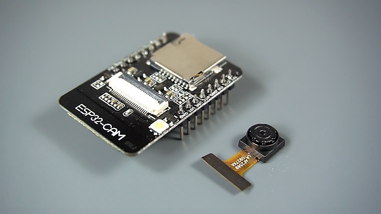
As described: “ The I2S subsystem in the ESP32 also provides a high speed bus connected directly to RAM for Direct Memory Access. Putting it simply, you can configure the ESP32 I2S subsystem to send or receive parallel data under hardware control. ”
Those. you can configure the I2S ESP32 interface to send or receive parallel data under hardware control, which is implemented for connecting the camera. This board is developed by Seeed Studio, the price is $ 9.90 here, but in our radio stores they sell for $ 8, apparently not only Seeed Studio can produce them.
Technical data:
- The smallest 802.11b / g / n Wi-Fi BT SoC Module
- Low power 32-bit CPU, can also serve the application processor
- Up to 160MHz clock speed , Summary computing power up to 600 DMIPS
- Built-in 520 KB SRAM, external 4MPSRAM
- Supports UART / SPI / I2C / PWM / ADC / DAC
- Support OV2640 and OV7670 cameras, Built-in Flash lamp.
- Support image WiFI upload
- Support TF card
- Supports multiple sleep modes.
- Embedded Lwip and FreeRTOS
- Supports STA / AP / STA + AP operation mode
- Support Smart Config / AirKiss technology
- Support for serial port local and remote firmware upgrades (FOTA)
Source of power
The platform was not controlled from autonomous power supply for a long time without recharging. Therefore, a 2A 18650 power supply module with a USB output with one slot was chosen as the source.

Specifications:
- Battery type: 18650 Li-Ion (no protection)
- Charger voltage: 5V to 8V
- Output voltages:
- 3V - directly from the battery through the protective device
- 5V - through a boost converter.
- Maximum output current:
- Output 3V - 1A
- Output 5V - 2A
- Maximum charging current: 1A
- Input Connector Type: micro-USB
- Output Connector Type: USB-A
- 5V consumers - from overload and short circuit
- Dimensions:
- PCB: 29.5 x 99.5 x 19mm
- Whole device: 30 x 116 x 20mm
ESP-WROOM-32 was selected as the main controller.

Earlier I described the characteristics of the ESP32 in more detail. Here are the basic characteristics of the module:
- Xtensa LX6 32-bit dual-core microprocessor up to 240 MHz
- Flash memory: 4 MB
- Wireless communication Wi-Fi 802.11b / g / n up to 150 Mb / s, Bluetooth 4.2 BR / EDR / BLE
- Support STA / AP / STA + AP modes, built-in TCP / IP stack
- GPIO 32 (UART, SPI, I2C, I2S interfaces, PWM, SD controllers, capacitive touch, ADC, DAC and more
- Power supply: via microUSB connector (CP2102 converter) or outputs
- Pin pitch: 2.54mm (can be inserted into breadboard)
- Board size: 5.2 x 2.8cm
Two optical encoders "Noname" are used as speed sensors for counting the pulses of rotation of the raster disks of the motor-wheel.

Characteristics:
- Supply voltage: 3.3V - 5V
- Sensor groove width: 6 mm;
- Output type: analog and digital
- Indicator: output status
The popular ultrasonic rangefinder HC-SR04 was used to measure the distance.

Features:
- Supply voltage: 5V
- Consumption in silent mode: 2mA
- Consumption during operation: 15 mA
- Distance range: 2-400 cm
- Effective viewing angle: 15
- Working viewing angle: 30 °
Software implementations
The first step was getting to know and flashing the ESP32 CAM module.
The description of working with the module is presented on Harba, here, here and on other resources.
Most of the articles describe a simple flashing process using the Arduino IDE. In most cases, this is enough, and at first this option was also fine with me.

In radio stores, ESP32-CAM modules are sold with an OV2640 camera, so a small change needs to be made in the sketch:
// Select camera model
//#define CAMERA_MODEL_WROVER_KIT
//#define CAMERA_MODEL_ESP_EYE
//#define CAMERA_MODEL_M5STACK_PSRAM
//#define CAMERA_MODEL_M5STACK_WIDE
#define CAMERA_MODEL_AI_THINKER
And also specify the SSID and password for the Wi-Fi access point
const char* ssid = "REPLACE_WITH_YOUR_SSID";
const char* password = "REPLACE_WITH_YOUR_PASSWORD";
One of the conditions for a web camera to work in my case is the ability to transmit a video stream through the Keenetic proxy server. I am using a Keenetik Viva home router. KeenDNS service provides the domain name to the home web resource. But to my surprise, the first attempt failed. When trying to remotely access via the Internet, I received the error "Header fields are too long for server to interpret". With this problem I first encountered. The solution to this problem is to change the CONFIG_HTTPD_MAX_REQ_HDR_LEN configuration, for example
#define CONFIG_HTTPD_MAX_REQ_HDR_LEN 2048
In the case of the Arduino IDE ESP32, the modules are already compiled and presented as static libraries, which are located in Windows along the path -% userprofile% \ AppData \ Local \ Arduino15 \ packages \ esp32 \ hardware \ esp32 \ 1.0.4 \ tools \ sdk \
Just changing the parameter in the header will do nothing.
That is, to change the configuration, we need to recompile the ESP-IDF libraries.
The solution was to clone the github.com/espressif/esp-who project . In the directory with examples, we find the camera_web_server project, change the parameter of the maximum header length, and also do not forget to specify the Wi-Fi connection settings.In

order for the project to compile, we had to install another checkbox - Support array 'rtc_gpio_desc' for ESP32

After successful compilation and loading of the project, go to the corresponding IP address in the browser and get to the page with the interface of our web camera.

The interface is similar to the Arduino examples, but some functionality has been added.
I made small changes to the original app_httpd.c file to control the GPIO_NUM_2 pin signal from the web interface. Although the description of the module talks about using pins for the needs of an SD card, but I do not use it, so I can use these pins.
void app_httpd_main()
{
	gpio_set_direction(GPIO_NUM_2, GPIO_MODE_OUTPUT);

static esp_err_t cmd_handler(httpd_req_t *req)
{
.......
// 736
else if(!strcmp(variable, "gpio2")) {
    		if (val == 0)
                gpio_set_level(GPIO_NUM_2, 0);
            else
                gpio_set_level(GPIO_NUM_2, 1);
    	}
For remote control, I made up for an uncomplicated Node-Red panel that runs on a Raspberry pi.

We managed to embed the video stream image into the template node:
<iframe
    src="http://192.168.1.61"
    width="300" height="300">
</iframe>
One point is important here: it is necessary to embed http, in the case of https there will be problems with the Content-Security-Policy. If problems arise in this case, you can try adding headers:
<script>
    var meta = document.createElement('meta');
    meta.httpEquiv = "Content-Security-Policy";
    meta.content = "default-src * 'unsafe-inline' 'unsafe-eval'; script-src * 'unsafe-inline' 'unsafe-eval'; connect-src * 'unsafe-inline'; img-src * data: blob: 'unsafe-inline'; frame-src *; style-src * 'unsafe-inline';";
document.getElementsByTagName('head')[0].appendChild(meta);
</script>
To control the GPIO_NUM_2 pin of the ESP32-CAM module, after making changes to the firmware, the following http GET request should be performed:
http://192.168.1.61/control?var=gpio2&val=1 // 0
On the panel interface, this is the wakeup switch, in the worker thread it looks like this

where the request function:
var newMsg = {}
var i = msg.payload ? 1 : 0;
newMsg.query = "control?var=gpio2&val=" + i
node.send(newMsg)
Settings of the http request node:

Other parameters and statuses are transmitted via MQTT
Wi-Fi and MQTT connectivity
I will give examples using the Arduino framework since I experimented on it as well. But in the end, I have a working application on ESP-IDF.
#Include <WiFi.h> header
Wi-Fi connection function for Arduino framework
void setup_wifi()
{
  Serial.println("Starting connecting WiFi.");
  delay(1000);
  for (int8_t i = 0; i < 3; i++)
  {
    WiFi.begin(ssid, password);
    uint32_t start = millis();
    while (WiFi.status() != WL_CONNECTED && ((millis() - start) < 4000))
    {
      Serial.print(".");
      delay(500);
    }
    if (WiFi.status() == WL_CONNECTED)
    {
      Serial.println("WiFi connected");
      Serial.println("IP address: ");
      Serial.println(WiFi.localIP());
      return;
    }
    else
    {
      Serial.println("Connecting Failed");
      //WiFi.reconnect(); // this reconnects the AP so the user can stay on the page
    }
  }
}
The function contains a loop for three iterations, since often fails to connect on the first try, and then waits endlessly for the WL_CONNECTED status. Maybe you can still solve it in another way, but it works like that.
Connecting to the MQTT for the Arduino framework is done using the github.com/knolleary/pubsubclient.git library .
To use the library, you need to include the header #include <PubSubClient.h>
MQTT connection function
bool setup_mqtt()
{
  if (WiFi.status() == WL_CONNECTED)
  {
    if (!client.connected())
    {
      client.setServer(mqtt_server, 1883);
      client.setCallback(callback);
    }
    Serial.print("Connecting to MQTT server ");
    Serial.print(mqtt_server);
    Serial.println("...");
    String clientId = "ESP32_car_client";
    if (client.connect(clientId.c_str()))
    {
      Serial.println("Connected to MQTT server ");
      //subscribing to topics
      client.subscribe("esp32/car/#");
      client.subscribe("esp32/camera/#");
      return true;
    }
    else
    {
      Serial.println("Could not connect to MQTT server");
      return false;
    }
  }
  return false;
}
First, we check that we are connected to Wi-Fi, then we connect to the broker client.setServer (mqtt_server, 1883);
And set the callback function client.setCallback (callback);
MQTT callback function
void callback(char *topic, byte *payload, unsigned int length)
{
  Serial.println("Message arrived ");
  memset(payload_buf, 0, 10);
  for (int i = 0; i < length; i++)
  {
    payload_buf[i] = (char)payload[i];
  }

  command_t mqtt_command = {
      .topic = topic,
      .message = payload_buf};
  xQueueSend(messageQueue, (void *)&mqtt_command, 0);
}
In case of successful connection, subscribe to topics
client.subscribe("esp32/car/#");
client.subscribe("esp32/camera/#");
There were some cases of MQTT connection dropping, so a check was added to the periodic polling task.
Periodic polling task
void pollingTask(void *parameter)
{
  int32_t start = 0;

  while (true) {
    if (!client.connected()) {
      long now = millis();
      if (now - start > 5000) {
        start = now;
        // Attempt to reconnect
        if (setup_mqtt()) {
          start = 0;
        }
      }
    }
    else {
      client.loop();
      int val = digitalRead(WAKEUP_PIN);
      if (val == LOW) {
        Serial.println("Going to sleep now");
        esp_deep_sleep_start();
      }
    }
    vTaskDelay(100 / portTICK_PERIOD_MS);
  }
  vTaskDelete(NULL);
}
An example of connecting to Wi-FI and MQTT using ESP-IDF was described in the previous article.In the
case of using ESP-IDF, there were no glitches when connecting to Wi-Fi and MQTT. One nuance when processing data from an MQTT topic in the esp_err_t mqtt_event_handler function (esp_mqtt_event_handle_t event): when the event type is MQTT_EVENT_DATA, you should take into account the event-> topic_len and event-> data_len parameters and take the topic name and data of exactly the appropriate length, otherwise we will get garbage. To do this, we can create buffer arrays or allocate memory dynamically (then free it), and copy the data, for example
strncpy(topic, event->topic, event->topic_len);
strncpy(data, event->data, event→data_len);
Sending data to a topic is done using the esp_mqtt_client_publish function
esp_mqtt_client_publish(client, topics[i], topic_buff[i], 0,0,0);
HC-SR04 Ultrasonic Sensor Data Processing
HC-SR04 is a cheap and popular sensor for designing microcontroller devices. As usual, there is a lot of material on the Internet on this topic: here and here. The description can also be viewed here, and a short datasheet here.
In short, to start measuring the distance, you must apply a high signal with a duration of 10 μs to the Trig pin. This initiates the sensor to transmit 8 cycles of a 40 kHz ultrasonic pulse and wait for the reflected ultrasonic pulse. When the transducer detects an ultrasonic signal from the receiver, it sets the Echo output high and delayed by a period (width) proportional to the distance. To calculate the distance, you need to calculate the formula:
distance = duration * 340 / = duration * 0.034 /,
340 m / s - the speed of sound propagation in air.

In the Arduino framework, the pulseIn function allows you to find out the pulse duration in μs.
For ESP-IDF there is an ESP-IDF Components library project , which also has an ultrasonic component for HC-SR04.
Sample code
esp_err_t ultrasonic_measure_cm(const ultrasonic_sensor_t *dev, uint32_t max_distance, uint32_t *distance)
{
    CHECK_ARG(dev && distance);

    PORT_ENTER_CRITICAL;

    // Ping: Low for 2..4 us, then high 10 us
    CHECK(gpio_set_level(dev->trigger_pin, 0));
    ets_delay_us(TRIGGER_LOW_DELAY);
    CHECK(gpio_set_level(dev->trigger_pin, 1));
    ets_delay_us(TRIGGER_HIGH_DELAY);
    CHECK(gpio_set_level(dev->trigger_pin, 0));

    // Previous ping isn't ended
    if (gpio_get_level(dev->echo_pin))
        RETURN_CRITICAL(ESP_ERR_ULTRASONIC_PING);

    // Wait for echo
    int64_t start = esp_timer_get_time();
    while (!gpio_get_level(dev->echo_pin))
    {
        if (timeout_expired(start, PING_TIMEOUT))
            RETURN_CRITICAL(ESP_ERR_ULTRASONIC_PING_TIMEOUT);
    }

    // got echo, measuring
    int64_t echo_start = esp_timer_get_time();
    int64_t time = echo_start;
    int64_t meas_timeout = echo_start + max_distance * ROUNDTRIP;
    while (gpio_get_level(dev->echo_pin))
    {
        time = esp_timer_get_time();
        if (timeout_expired(echo_start, meas_timeout))
            RETURN_CRITICAL(ESP_ERR_ULTRASONIC_ECHO_TIMEOUT);
    }
    PORT_EXIT_CRITICAL;

    *distance = (time - echo_start) / ROUNDTRIP;

    return ESP_OK;
}
There is an explanation of the algorithm in the comments. The pulse duration is measured in the while loop while the signal level is high on the Echo pin (after // got echo, measuring) after which the distance is measured
*distance = (time - echo_start) / ROUNDTRIP
The coefficient for obtaining the distance in centimeters ROUNDTRIP = 58.
In the Arduino framework it looks even easier
Sample code
#include "ultrasonic.h"

portMUX_TYPE mux = portMUX_INITIALIZER_UNLOCKED;
#define PORT_ENTER_CRITICAL portENTER_CRITICAL(&mux)
#define PORT_EXIT_CRITICAL portEXIT_CRITICAL(&mux)

Ultrasonic::Ultrasonic() {
  pinMode(GPIO_NUM_33, OUTPUT);
  pinMode(GPIO_NUM_26, INPUT);
}

uint32_t Ultrasonic::calculateDistance() {
    PORT_ENTER_CRITICAL;
    digitalWrite(GPIO_NUM_33, LOW);
    delayMicroseconds(2);
    digitalWrite(GPIO_NUM_33, HIGH);
    delayMicroseconds(10);
    digitalWrite(GPIO_NUM_33, LOW);
    duration = pulseIn(GPIO_NUM_26, HIGH);
    PORT_EXIT_CRITICAL;
    distance = duration / 58;
    return distance;
}

uint32_t Ultrasonic::getDistance() {
    return distance;
}
There was an attempt to use the ultrasonic ESP-IDF library for the ESP32 Arduino project, but this case works until the first sensor glitch. Why so, it was not possible to find out exactly. A sensor glitch is a periodic miscalculation in pulses and the issuance of false readings, in the calculated figures it looks like a distance of more than 20,000 cm. On the forums they write that this is due to a poor-quality sensor (Chinese copy).
Speed measurement with optical sensors
The optical module for reading pulses is based on an LM393 comparator and a slot sensor. Designed for use with raster discs that fit over the shaft of a gearbox or electric motor.
As usual, there are already articles on this topic: digitrode.ru , mirrobo.ru , and arduino-kit.ru .
Sensor circuit:

In the Arduino framework, we calculate the speed as follows:
- define the variable (structure) of the counter, for example
typedef struct {
  int encoder_pin = ENCODER_PIN; // pulse output from the module
  unsigned int rpm = 0; // rpm reading
  volatile byte pulses = 0; // number of pulses
  unsigned long timeold = 0;
  unsigned int pulsesperturn = 20;
} pulse_t;
Then, in the setup function, we must register the input pin and interrupt to it
pinMode(pulse_struct.encoder_pin, INPUT);
attachInterrupt(pulse_struct.encoder_pin, counter, FALLING);
Next, the number of revolutions per minute is calculated
pulse_struct.rpm =
        (60 * 1000 / pulse_struct.pulsesperturn )/
        (1000)* pulse_struct.pulses;
Sample code
void pulseTask(void *parameters) {
  sensor_data_t data;
  data.sensor = OPTICAL_SENSOR;
  portBASE_TYPE xStatus;

   while (true) {
      //Don't process interrupts during calculations
      detachInterrupt(0);
      pulse_struct.rpm =
        (60 * 1000 / pulse_struct.pulsesperturn )/
        (1000)* pulse_struct.pulses;
      pulse_struct.pulses = 0;
      data.value = pulse_struct.rpm;
      //Restart the interrupt processing
      attachInterrupt(0, counter, FALLING);
      Serial.print("optical: ");
      Serial.println(data.value);
     //Sending data to sensors queue
    xStatus = xQueueSend(sensorQueue, (void *)&data, 0);
    if( xStatus != pdPASS ) {
     printf("Could not send optical to the queue.\r\n");
    }
    taskYIELD();
    vTaskDelay(1000 / portTICK_PERIOD_MS);
   }
}
In ESP-IDF, you can use the hardware counter PCNT, which was described in the previous article, for this purpose .
Sample code of the task being processed
typedef struct {
uint16_t delay; //delay im ms
int pin;
int ctrl_pin;
pcnt_channel_t channel;
pcnt_unit_t unit;
int16_t count;
} speed_sensor_params_t;
void pulseTask(void *parameters) {
sensor_data_t data_1;
sensor_data_t data_2;
data_1.sensor = OPTICAL_SENSOR_1;
data_2.sensor = OPTICAL_SENSOR_2;
portBASE_TYPE xStatus;
speed_sensor_params_t params_1 = {
.delay = 100,
.pin = ENCODER_1_PIN,
.ctrl_pin = GPIO_NUM_0,
.channel = PCNT_CHANNEL_0,
.unit = PCNT_UNIT_0,
.count = 0,
};
ESP_ERROR_CHECK(init_speed_sensor(¶ms_1));
speed_sensor_params_t params_2 = {
.delay = 100,
.pin = ENCODER_2_PIN,
.ctrl_pin = GPIO_NUM_1,
.channel = PCNT_CHANNEL_0,
.unit = PCNT_UNIT_1,
.count = 0,
};
ESP_ERROR_CHECK(init_speed_sensor(¶ms_2));
while(true) {
data_1.value = calculateRpm(¶ms_1);
data_2.value = calculateRpm(¶ms_2);
sensor_array[OPTICAL_SENSOR_1] = data_1.value;
sensor_array[OPTICAL_SENSOR_2] = data_2.value;
printf("speed 1 = %d\n", data_1.value);
printf("speed 2 = %d\n", data_2.value);
xStatus = xQueueSend(sensorQueue, (void *)&data_1, 0);
xStatus = xQueueSend(sensorQueue, (void *)&data_2, 0);
if( xStatus != pdPASS ) {
printf("Could not send optical to the queue.\r\n");
}
vTaskDelay(100 / portTICK_PERIOD_MS);
}
}
PWM control
You can read about controlling servo drives on Arduino at developer.alexanderklimov , wiki.amperka.ru .
As stated in the source above: "A servo is a mechanism with an electric motor that can turn to a given angle and hold its current position." In practice, we are dealing with pulse-width modulation, where the angle of rotation of the actuator depends on the signal pulse width.

For ESP32 on an Arduino framework, you can use the ESP32Servo library
For this, we connect the header
#include <ESP32Servo.h>Create an object
Servo servo_horisontal;We indicate the output pin
servo_horisontal.attach(SERVO_CAM_HOR_PIN);After that we can write down the required value of the amount of rotation
servo_horisontal.write(value);PWM control for other types of devices on the Arduino framework is done using the esp32-hal-ledc.h library . ESP32
microcontrollers do not support the standard Arduino analogWrite () function for PWM. Instead of them, functions are
provided : ledcSetup (channel, freq, resolution_bits) - the channel, frequency and resolution are
indicated ledcAttachPin (GPIO, channel) - the port and channel are indicated
ledcWrite (channel, dutycycle) - the channel and duty cycle of the PWM signal are indicated
Examples can be seen
How As the name suggests, the functions were originally designed to control LED modules, but they are also used for other purposes.
In the ESP-IDF framework, the servo drive is controlled in the same way as the commutator control using the MCPWM module, as described in the previous article. An example of MCPWM servo motor control can be viewed here
Sample code
static uint32_t servo_per_degree_init(uint32_t degree_of_rotation)
{
    uint32_t cal_pulsewidth = 0;
    cal_pulsewidth = (SERVO_MIN_PULSEWIDTH + (((SERVO_MAX_PULSEWIDTH -          SERVO_MIN_PULSEWIDTH) * (degree_of_rotation)) / (SERVO_MAX_DEGREE)));
    return cal_pulsewidth;
}

void mcpwm_example_servo_control(void *arg)
{
    uint32_t angle, count;
    //1. mcpwm gpio initialization
    mcpwm_example_gpio_initialize();

    //2. initial mcpwm configuration
    printf("Configuring Initial Parameters of mcpwm......\n");
    mcpwm_config_t pwm_config;
    pwm_config.frequency = 50;    //frequency = 50Hz, i.e. for every servo motor time period should be 20ms
    pwm_config.cmpr_a = 0;    //duty cycle of PWMxA = 0
    pwm_config.cmpr_b = 0;    //duty cycle of PWMxb = 0
    pwm_config.counter_mode = MCPWM_UP_COUNTER;
    pwm_config.duty_mode = MCPWM_DUTY_MODE_0;
    mcpwm_init(MCPWM_UNIT_0, MCPWM_TIMER_0, &pwm_config);    //Configure PWM0A & PWM0B with above settings
    while (1) {
        for (count = 0; count < SERVO_MAX_DEGREE; count++) {
            printf("Angle of rotation: %d\n", count);
            angle = servo_per_degree_init(count);
            printf("pulse width: %dus\n", angle);
            mcpwm_set_duty_in_us(MCPWM_UNIT_0, MCPWM_TIMER_0, MCPWM_OPR_A, angle);
            vTaskDelay(10);     //Add delay, since it takes time for servo to rotate, generally 100ms/60degree rotation at 5V
        }
    }
}
Those. we need to initialize the module using the mcpwm_init function (MCPWM_UNIT_0, MCPWM_TIMER_0, & pwm_config);
And then set the angle value
mcpwm_set_duty_in_us (MCPWM_UNIT_0, MCPWM_TIMER_0, MCPWM_OPR_A, angle);
Examples of using the MCPWM module for different drive types can be found on github .
An example of brushed motor control was also presented in the previous article.
It should be noted that such a platform is a differentially controlled nonholonomicsystem. Motors have variability in performance, so you have to set a software offset for one of them to ensure a uniform speed. You can get acquainted with the theory at robotosha.ru robotosha.ru/robotics/robot-motion.html . For optimal control of geared motors, a PID algorithm with feedback in the form of optical sensors is used. The description of the algorithm is presented here and here .
A description of the equations of motion, as well as control algorithms, is beyond the scope of this article. Differential kinematics is not yet implemented in code.
Sleep modes
According to the documentation , as well as the description in the article, the ESP32 can switch between different power modes:
- Active mode
- Modem Sleep mode
- Light Sleep mode
- Deep sleep mode
- Hibernation mode
The table shows the differences in current consumption in different modes.

I used the Deep Sleep mode in the absence of a high signal on the GPIO_NUM_13 pin
gpio_set_direction(WAKEUP_PIN, GPIO_MODE_INPUT);
esp_sleep_enable_ext0_wakeup(WAKEUP_PIN,1); //1 = High, 0 = Low
In the absence of external influence, I pulled up the 10k input with a resistor to 3.3 V, although it is possible in software. And in the task of periodic polling, I check the state of the input signal
if(!gpio_get_level(WAKEUP_PIN)) {
         printf("Going to sleep now\n");
        esp_deep_sleep_start();
    }
This will complete the description. A practical example of using ESP32 modules with various peripherals was shown. Some issues of software implementation and comparison of ESP-IDF and Arduino approaches are also touched upon.