What is the exact time for?
Of the functions that the time server allows to perform, we can name the correct formation of the chronology of events in control systems for maintaining appropriate logs, logs, archiving information, building trends, graphs, etc.
In video surveillance systems, the timeserver provides linking of the captured video to astronomical time. Also, the device allows you to accurately compare information from different information systems at the enterprise. For example, it can be video surveillance systems and security systems, such as ACS, relay protection systems and independent telemechanics systems, etc.
A number of information exchange protocols use time stamps directly as part of transmitted data packets. These protocols include IEC-101/104, used in modern telemechanics systems.
One of the important requirements for a number of industrial applications is information security requirements that exclude Internet access to perform the time synchronization function.
Due to its simplicity and a number of historical reasons for solving the problem of time synchronization, the NTP protocol is most widely used. In addition to servers, archive and operator stations of control systems, controllers and HMI panels, network equipment of communication systems (managed switches, routers, etc.) can act as NTP clients in an enterprise.
NTP protocol
Network time protocol (NTP) is a network protocol for synchronizing clocks in computer systems over packet-switched data networks with variable delay (latency). The high popularity of the protocol is due to the active development of Ethernet-based systems. One of the key advantages of the protocol is the ability to transmit time stamps directly over the data network, which eliminates the need for a separate time bus, such as in 1PPS or IRIG-B systems. The protocol was developed in 1985 and is one of the oldest Internet protocols in use today.
NTP provides acceptable timing accuracy for most applications. The protocol can support time with an accuracy of tens of milliseconds on the Internet and up to 0.2 ms on local networks under ideal conditions. Asymmetric data paths and network congestion can lead to errors of 100ms or more.
NTP synchronizes devices to Coordinated Universal Time (UTC). At the same time, the protocol takes into account the appearance of a leap second as a result of uneven rotation of the Earth, but does not transmit any information about local time zones or daylight saving time.
System structure
NTP uses a hierarchical system of accurate time sources. Each level of the hierarchy is called a Stratum (stratum, layer) and is assigned a number starting at 0 for the reference clock at the top of the hierarchy. The time server on the N layer is synchronized from the servers on the N-1 level. The number N represents the distance from the reference clock and is used to prevent cycling during synchronization. Stratum is not always a measure of quality or reliability. For example, you can find time sources on layer 3 that are of a higher quality than time sources on layer 2.
Stratum 0
The reference clock on the Stratum 0 is satellite navigation systems (GLONASS, GPS, etc.), atomic clocks or radio transmitters. Once per second, they generate a pulse signal (1PPS) that triggers an interrupt and generates a time stamp on the connected devices. Layer 0 devices are also known as reference clocks. NTP servers cannot position themselves in the system as Stratum 0. If the Stratum field is set to 0 in a data packet, this indicates an undefined layer.

The logical structure of the synchronization system based on NTP
Stratum 1
This layer contains devices whose system time is synchronized to within a few microseconds from the reference clock. Time servers at this level can work in peer-to-peer mode with other Stratum 1 servers for redundancy and accuracy verification. They are also called primary time servers.
Stratum 2
These are devices that sync across the network from Tier 1 servers. Often Tier 2 devices poll multiple Tier 1 servers. Stratum 2 computers can also be peer-to-peer with other Stratum 2 computers to provide more stable and reliable time for all devices in a peer group. nodes.
The maximum theoretical number of layers is 15; Stratum 16 is used to indicate that the device is out of sync. NTP mechanisms on each device in the system interact to create the shortest path to the Stratum 1 servers for all clients. This minimizes the accumulated latency in data transmission and improves timing accuracy. The algorithm for constructing a spanning tree with a minimum path length is based on the Bellman-Ford algorithm.
Time stamps
NTP originally used 64-bit timestamps, consisting of a 32-bit portion for seconds and a 32-bit portion for fractions of a second, which gave a timeline that would scroll every 32 seconds (136 years) and give a theoretical resolution of 2 -32 seconds (233 picoseconds). The countdown began on January 1, 1900, so the first epoch would end on February 7, 2036.
The latest version of the NTPv4 protocol introduces a 128-bit time format: 64 bits for seconds and 64 bits for fractions of a second, which gives a timeline of over 584 billion years and a resolution of 0.05 attoseconds. Additionally, a 32-bit era number field was introduced, which eliminated even the theoretical problem of the end of each era.
Clock synchronization algorithm
The NTP client polls one or more servers regularly. In doing so, it calculates the time offset and round trip delay. The time offset θ is the difference in absolute time between the server and client clocks and is determined by the formula:

Round-trip delay δ is defined as the time a signal is transmitted over the communication lines from the client to the server and back. This is the time taken to send the signal, plus the time required to confirm that a signal has been obtained by:

where t 0 - mark time client for transmitting a request packet,
t 1 - timestamp receiving server request packet,
t 2 - a label server time for response packet transmission,
t 3- timestamp of the client receiving the response packet.

Algorithm for calculating the time offset and round-trip delay
The calculated values of θ and δ are passed through filters and subjected to statistical analysis. Outliers from the total sample are discarded and the timing bias is estimated based on the remaining values. Knowing the time offset and round trip delay, the client adjusts its own time to achieve θ equal to zero.
Accurate synchronization is achieved when the inbound and outbound routes between the client and the server are symmetric, that is, have the same latency. If the routes are asymmetric, then there is a systematic bias of half the difference between the time a packet is sent from the client to the server and back.
Transmission mechanisms
In most cases, the NTP protocol uses the classic client-server model of operation, in which the client sends a request and after a while receives a response from the server. However, the protocol can work in peer-to-peer systems, where two peers see each other as a potential time source. This mode of operation is also called symmetrical. For network communication, NTP uses the UDP protocol, by default working on port 123. For data transmission, various mechanisms can be used - unicast, broadcast, multicast and manycast.
Unicast mode
NTP most often uses Unicast mode for data transfer. In this mode, data is transferred from one network device to another individually. Unicast packets use the specific address of the device for which the packet is intended as the destination IP address.
Broadcast
mode This mode is convenient in cases where a small number of NTP servers serve a large number of clients. In this mode, the server periodically sends out packets using the broadcast subnet address. A client configured to synchronize in this way receives the server's broadcast packet and synchronizes with it.
This mode has a number of features. First, the Broadcast mode provides lower timing accuracy than Unicast. Secondly, broadcast packets can only be transmitted within the same subnet. In addition, it is advisable to use authentication methods to protect against intruders.
Multicast mode Multicast
mode works in the same way as Broadcast. The difference is that not the broadcast subnet address, but the multicast group address is used to deliver packets. Clients and servers are assigned a multicast IP address that they use for time synchronization. This makes it possible to synchronize groups of machines located on different subnets, provided that the routers connecting them support IGMP and are configured to transmit multicast traffic.
Manycast Mode
This mode is new to the latest version (v4) of the NTP protocol. Manycast mode functions as Multicast mode only with unknown IP addresses of NTP servers. By sending Multicast messages, the client searches the Manycast server network, receives time samples from each of them, and selects the three "best" servers with which it will synchronize. In case of failure of one of the servers, the client automatically updates his list.
Clients and servers operating in Manycast mode also use multicast group addresses to transmit time samples. Clients and servers using the same address form one association. The number of associations is determined by the number of multicast addresses used.
Protocol versions
Since its appearance in 1985, the protocol began to actively develop and by 1992 had changed four versions (from NTPv0 to NTPv3). Each new version added functionality and optimized its work, but left the data format unchanged and kept the different versions compatible with each other. The last fourth version of the protocol is dated 2010. NTP continues to evolve today, work is underway to create a solution that is technically similar to the more accurate PTP (Precision Time Protocol).
SNTP
Simultaneously with NTPv3, a simpler version of the protocol, SNTP (Simple NTP), was introduced in 1992. SNTP uses the same transmission and presentation format as NTP. At the same time, SNTP does not concern the algorithms of the server, but simplifies the algorithms of the clients. That is why the protocol is most often used in embedded systems and devices that do not require high accuracy.
The difference between NTP and SNTP lies in the methods of determining the optimal servers for synchronization and the method of time correction. This is how NTP allows the client to use the mathematical intersection algorithm (a redesigned version of Marzullo's algorithm) to select several of the best servers on the network and smoothly adjust their time. SNTP uses one predefined NTP server for synchronization, while others can only be backups in case of loss of communication with the main device. In this case, a client using SNTP is able to adjust the time only in a jump after receiving a response from the server.
Typical diagram of the synchronization system and its disadvantages
Traditionally, a precision time system at industrial facilities is based on an NTP server consisting of a head unit mounted in the same cabinet with network equipment and a remote antenna that is installed outdoors and connected to the server using a coaxial cable. At the same time, the head unit has several network interfaces (Ethernet or RS-232/485) for connecting clients in one or several networks.

Typical Precision Time System
If you look at this solution more closely, you will see several disadvantages. First, such a system lacks full redundancy. Despite the fact that the head unit has several network interfaces and is able to provide accurate time in several networks, its failure or failure will lead to the loss of the source of accurate time throughout the site. Full redundancy of the head unit in such a solution will make the already expensive synchronization system even more expensive.
The second drawback is the need to install a time server in the cabinet. This is not a disadvantage for large projects, but for small local control systems it can be a serious problem.
Also, the disadvantages include the need to use a remote antenna and coaxial cable. Why? First of all, the cost of a high-quality GPS / GLONASS antenna with a long cable and protection against rodents can easily exceed 10,000 rubles. in 2020 prices. In this case, coaxial cables have a limited length for transmitting signals from satellite systems. Above 50 m, the signal will attenuate significantly, which is a serious limiting factor in large buildings.
The main disadvantage of the traditional approach to the creation of synchronization systems is its high cost (often more than 150,000 rubles), which significantly affects the estimate of not only small projects, but also quite large ones.
How to make the system cheaper and more reliable
The unconditional trend of modern technologies is the creation of more compact and user-friendly electronic devices. In this regard, time servers are no exception.
The entire synchronization solution, including the GPS / GLONASS antenna, can fit in a small box, as is done in
FL TIMESERVER from Phoenix Contact. The device is made on the principle of a smart antenna, that is, it directly combines the functionality of a time server and a GPS / GLONASS receiver antenna. Its design is the only thing that distinguishes it from the usual solutions.
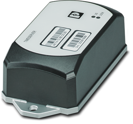
FL TIMESERVER NTP time server
As practice shows, the device is capable of providing communication with satellite systems even inside buildings, but for more reliable reception of signals it can be operated in outdoor conditions, because it is made in a case with a dust and moisture protection level IP68 and is capable of operating in a wide temperature range from -40 to +70 C In this case, the time server is mounted as a conventional antenna, has a redundant power supply from the 24 V DC circuit and / or via an Ethernet cable (PoE) and is diagnosed using SNMP. For outdoor installations, a sealed cable gland is used to maintain a high level of dust and moisture protection.
In terms of functionality, there are no differences: the device is able to receive time stamps and geolocation data from satellite navigation systems (GLONASS, GPS) and broadcast this information to clients on an Ethernet network.

Precision time system based on Phoenix Contact solution
With this solution, the synchronization system is greatly simplified and eliminates the drawbacks of the traditional approach. FL TIMESERVERhas only one Ethernet port, but if you need to use several interfaces, you just need to connect it to a switch or use several smart antennas. In this case, we will get a full-fledged backup of time servers, and not just its network interface. In this case, the final solution will still be cheaper than many existing analogues. FL TIMESERVER can be moved outside the network or automation cabinet, saving space inside. This solution does not require a separate antenna, here it is already built-in and we can connect to the enterprise network with a regular Ethernet cable. In turn, this allows you to move the time server at a distance of up to 100 m from the main equipment without fear that the signal will fade. The most important advantage of such a solution is a completely different price order.The cost of one time server is less than 300 euros, which makes it convenient to use in both small and large projects.