Hardware part of the project
Here is a list of the components that make up my project:
- Arduino Pro Mini board.
- Connector GX-12 (plug).
- Three-axis accelerometer MMA7660.
- Display PCD8544 for Nokia 5110/3310.
- Battery charger for TP4056 lithium polymer batteries.
- DD0505MD converter.
- Lithium polymer battery, size 14500.
Screen
The screen that I decided to use in this project has been with me for a long time. When I discovered it, I immediately wondered why I hadn’t used it anywhere else. I found a library to work with it, connected the power to it. After that, I immediately found the answer to my question. It was about its contrast and the fact that it needed additional components to work. I found thislibrary for working with the display and learned that a potentiometer can be connected to an analog pin. I decided to use an accelerometer to adjust the contrast of the display. Namely, if you go to the settings menu, tilting the device to the left leads to a decrease in the corresponding value, and tilting to the right - to an increase. I added a button to the device, by pressing which the current contrast settings are saved in the EEPROM.
Accelerometer driven menu
It seemed to me that navigating the menu using buttons is too boring. Therefore, I decided to try using a gyroscope to work with the menu. This scheme of interaction with the menu turned out to be very successful. Thus, tilting the device to the left opens the contrast adjustment menu. As a result, you can go to this menu even if the display contrast deviates greatly from the norm. I also used an accelerometer to select the various applications I created. Here is the library I used in this project.
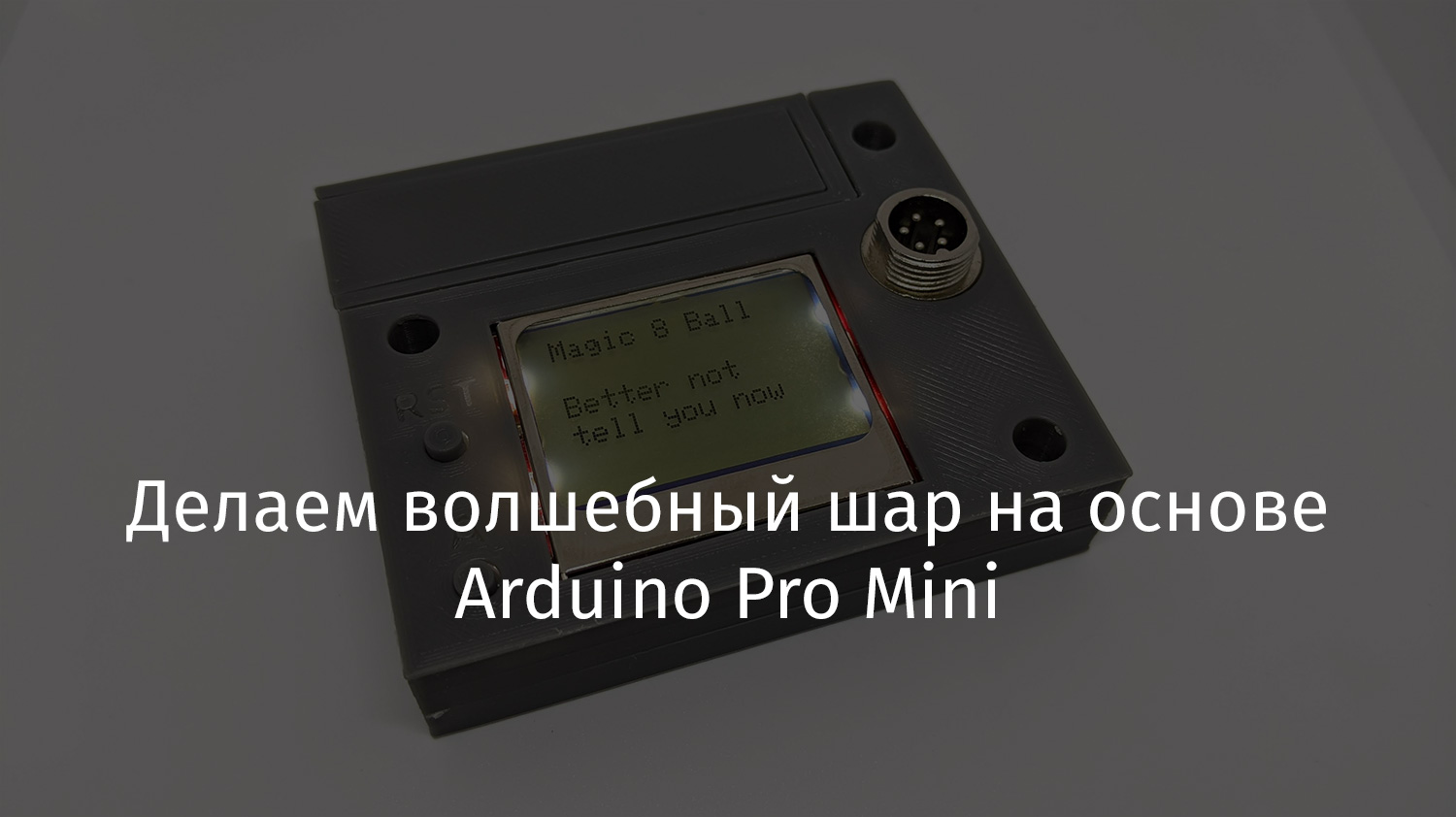
Applications
At first I wanted to do something that could play the role of a magic ball. But then I decided that I could equip what I got with the additional capabilities provided by various applications. For example, I wrote a program that simulates a roll of a dice, which randomly produces a number from 1 to 6. Another program of mine was able to answer the questions "Yes" and "No." She helps to make decisions in difficult situations. You can add other apps to my device.
Battery
The problem with my projects is that I always use non-removable lithium polymer batteries in them. And then, when these projects are forgotten for a while, something bad can happen to the batteries. This time I decided to do it differently and make it so that the battery from the device, if necessary, could be removed. For example, it can be useful in some new project. By that time I had already designed the case for the battery, but I had to finish it with a door. The first copies of the case turned out to be unreasonably complex and cumbersome. So I redesigned it. It can be useful in my other projects as well.
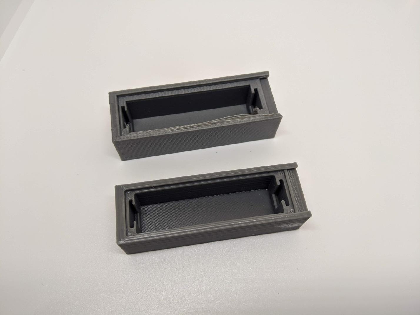
Battery
case I originally wanted to fix the case cover with a magnet, but I really don't like using any additional components where they can be dispensed with. So I decided to make a snap-on lid. What I did in the beginning was not very good for 3D printing. So I redid the cover. As a result, it was printed well.
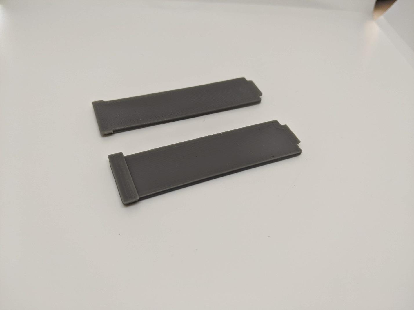
Battery case cover
I was satisfied with the result, but the use of such a battery compartment in my projects limits the possibilities for their design, since the compartment cover should be on the top of the device. I tried to build the battery compartment into the device body so that the cover would go to the side of the case, but nothing good came of it.
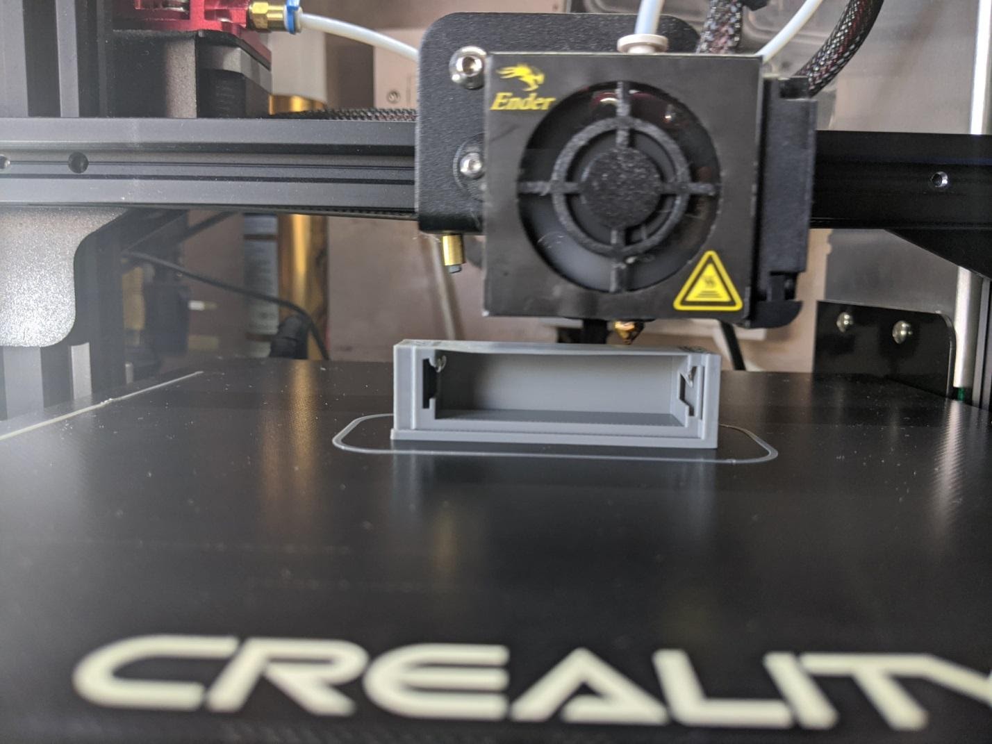
Battery Case Printing
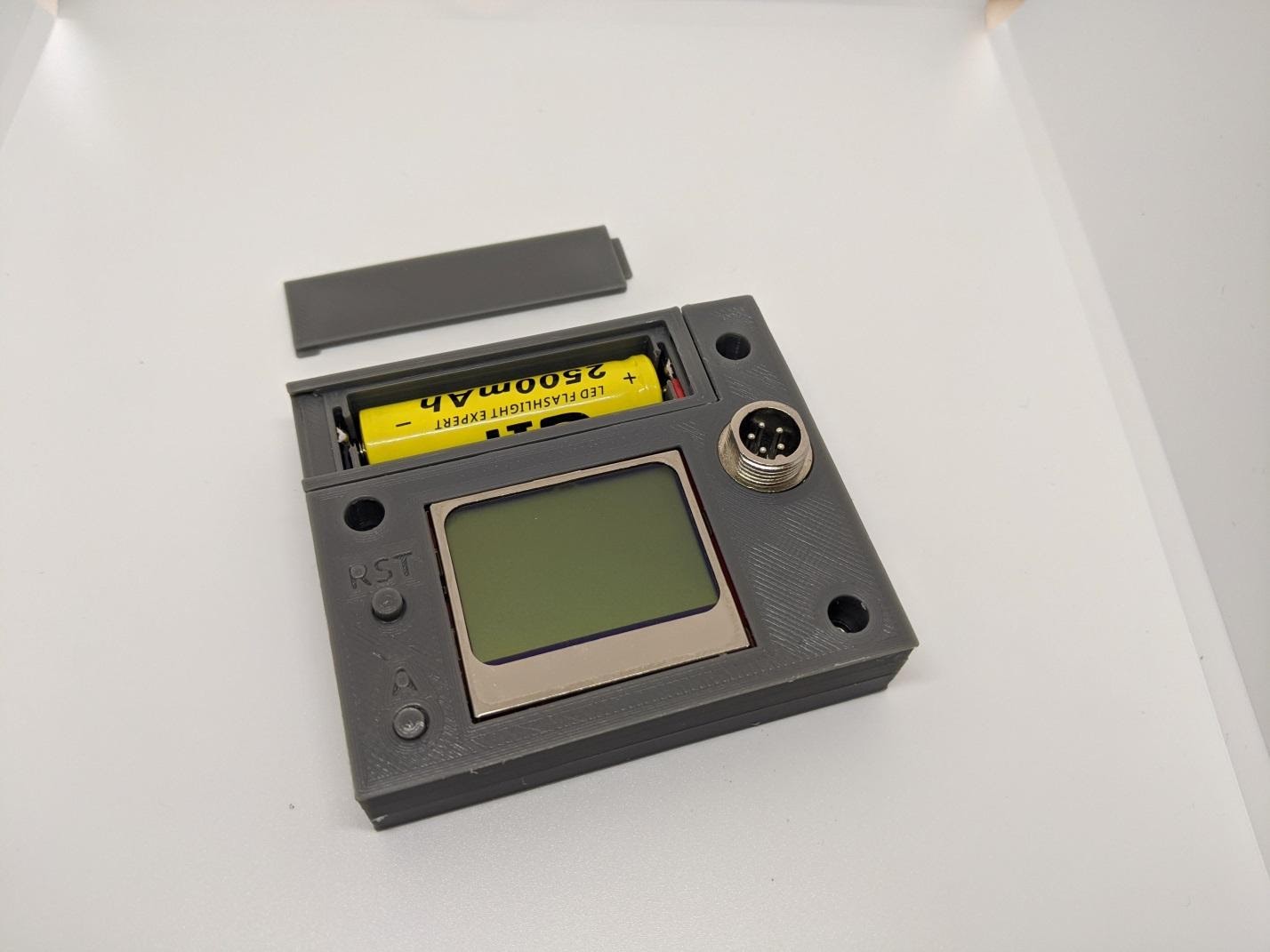
The battery cover is located on the top of the device
Solving nutrition issues
I did not want to connect elements to the main board for organizing the power supply of the device, as this would increase its size and increase the cost of the project. I thought that it would be ideal if I could integrate the TP4056 charger and DD0505MD converter I already have into the project. That way I wouldn't have to spend money on additional components.
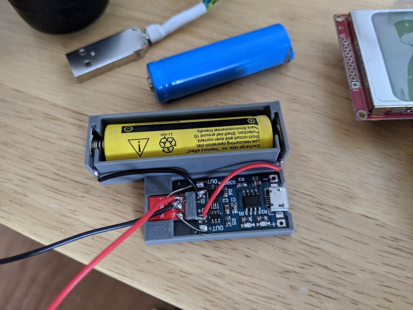
Solving device power issues
I did it. The boards turned out to be where they should be, I connected them using soldering with short rigid wires, which made the resulting design very compact. A similar structure can be built into my other projects.
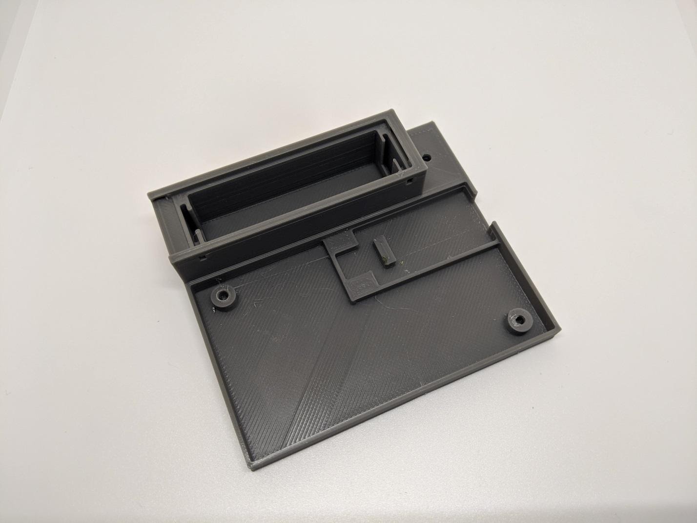
The inner part of the case with space for the elements that provide the device with power
In the course of work on the project, one trouble happened to him. After I collected everything, I dropped the device on the floor. After that, the display stopped working. At first I thought it was the display. So I reconnected it, but that didn't fix anything. The problem with this project was poor component placement. Namely, I, to save space, mounted the display over the Arduino. In order to get to the Arduino, I had to unsolder the display. But soldering the display did not solve the problem. In this project, I used a new Arduino board. I have another such board that I use to experiment with a breadboard. When I connected the screen to it, everything worked. Since I was using surface mounting, I had to unsolder the pins from this board. Pulling the pins out of the board, I made a short circuit,by connecting the VCC and GND pins. The only thing left for me was to order a new board. But I didn't have time for that. Then I decided to take the chip from the circuit board on which the short occurred and move it to the "dead" board. I solved this problem with the help of a hot air soldering station. To my surprise, it worked. I just needed to use the pin to reboot the board.
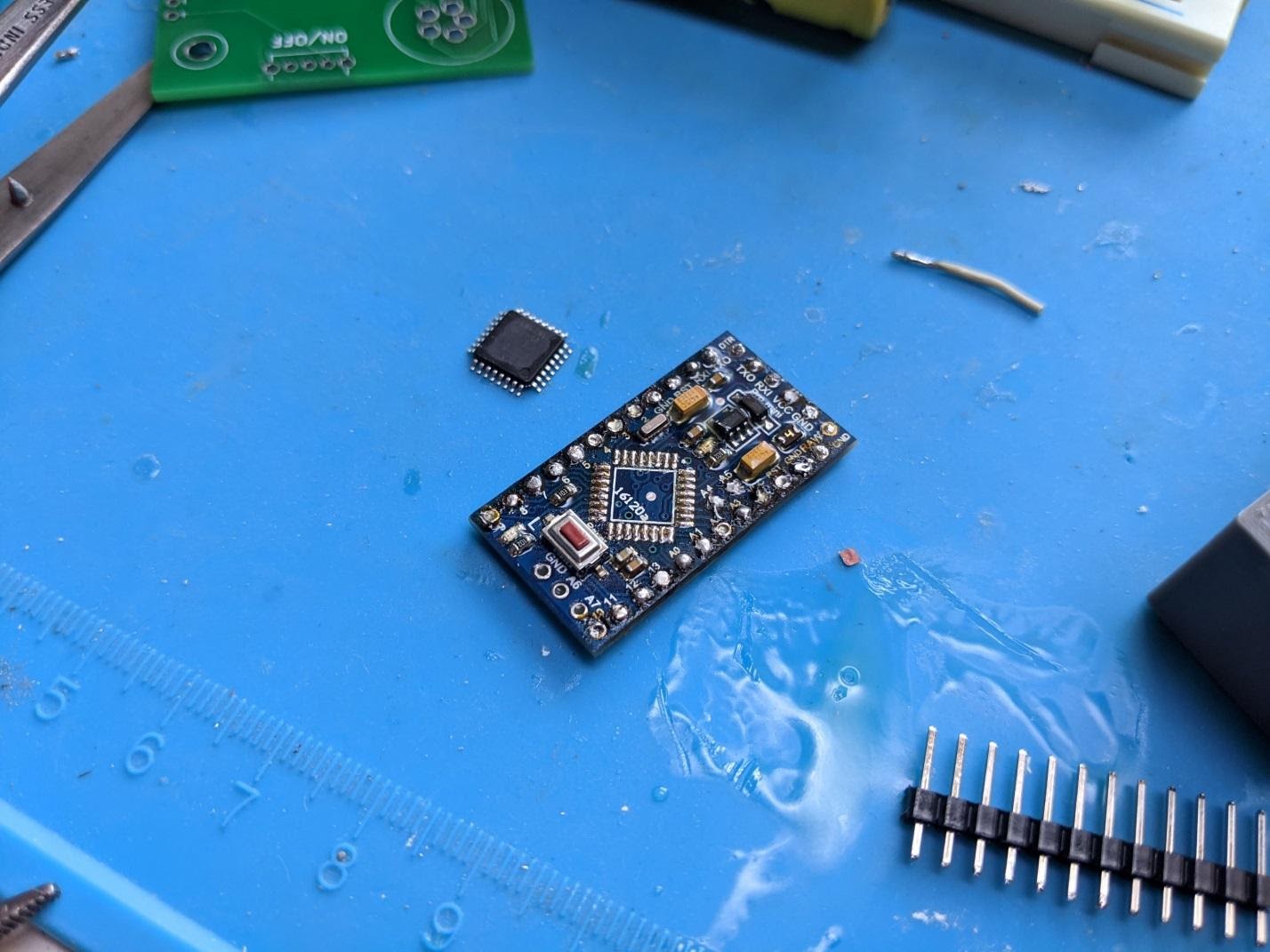
Board with the chip removed
Normally, I would not go to such extremes. But my Arduino board was only a week old. That's why I went for this experiment. Perhaps the pandemic has made me more experimental and more resourceful.
Lanyard attachment
I equip my projects with lace fasteners. After all, you never know in advance when and where you will use them.
Outcome
This is how it looks like working with the resulting magic ball.
Here you can find files for 3D printing the enclosure. You can look here to see the code.
Do you use Arduino Pro Mini in your projects?