First, you need to connect the display to the controller. We connect according to the scheme:
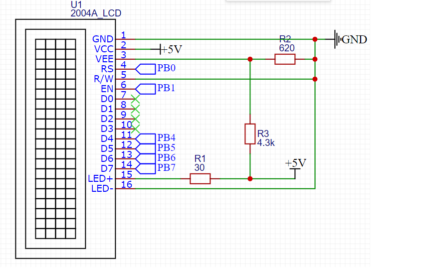
PB0 - PB7 - controller outputs.
Display pin assignment:
| Pin number | Signal | Signal assignment |
| 1 | GND | Ground (common wire) |
| 2 | VCC | Power + 5V |
| 3 | VEE | . . 10-20 , . |
| 4 | RS | : 0 – ; 1 – . |
| 5 | R/W | :
0 – ; 1 – . , . |
| 6 | EN | . , «» . |
| 7 | DB0 | . . |
| 8 | DB1 | |
| 9 | DB2 | |
| 10 | DB3 | |
| 11 | DB4 | . |
| 12 | DB5 | |
| 13 | DB6 | |
| 14 | DB7 | |
| 15 | A | (+) |
| 16 | K | (-). . |
So, the display is connected. It's time to teach the microcontroller to work with it. I decided to create my own library in order to be able to use it in different projects. It consists of two files - lcd_20x4.h and lcd_20x4.c
Let's start with the header file.
#ifndef LCD_LCD_20X4_2004A_LCD_20X4_H_
#define LCD_LCD_20X4_2004A_LCD_20X4_H_

#include "stm32f1xx.h"
#include "delay.h"
First, we include the CMSIS library file stm32f1xx.h since I have a STM32F103C8T6 stone. With the next inclusion, we include the file delay.h - this is my library for working with delays based on the system timer. I will not describe it here, here is its code:
Delay.h file
#ifndef DELAY_DELAY_H_
#define DELAY_DELAY_H_

#include "stm32f1xx.h"

#define F_CPU 72000000UL
#define US F_CPU/1000000
#define MS F_CPU/1000
#define SYSTICK_MAX_VALUE 16777215
#define US_MAX_VALUE SYSTICK_MAX_VALUE/(US)
#define MS_MAX_VALUE SYSTICK_MAX_VALUE/(MS)


void delay_us(uint32_t us); //  233
void delay_ms(uint32_t ms); //  233
void delay_s(uint32_t s);

#endif /* DELAY_DELAY_H_ */
Delay.c file
#include "delay.h"


/*      */

void delay_us(uint32_t us){ //  233 016

	if (us > US_MAX_VALUE || us == 0)
		return;

	SysTick->CTRL &= ~SysTick_CTRL_TICKINT_Msk; //     0
	SysTick->CTRL |= SysTick_CTRL_CLKSOURCE_Msk; //
	SysTick->LOAD = (US * us-1); //
	SysTick->VAL = 0; //     SYST_CVR
	SysTick->CTRL |= SysTick_CTRL_ENABLE_Msk; //

	while(!(SysTick->CTRL & SysTick_CTRL_COUNTFLAG_Msk)); //    COUNFLAG   SYST_CSR

	SysTick->CTRL &= ~SysTick_CTRL_COUNTFLAG_Msk;	//   COUNTFLAG
	SysTick->CTRL &= ~SysTick_CTRL_ENABLE_Msk; //

}

void delay_ms(uint32_t ms){ //  233

	if(ms > MS_MAX_VALUE || ms ==0)
		return;

	SysTick->CTRL &= ~SysTick_CTRL_TICKINT_Msk;
	SysTick->CTRL |= SysTick_CTRL_CLKSOURCE_Msk;
	SysTick->LOAD = (MS * ms);
	SysTick->VAL = 0;
	SysTick->CTRL |= SysTick_CTRL_ENABLE_Msk;

	while(!(SysTick->CTRL & SysTick_CTRL_COUNTFLAG_Msk));

	SysTick->CTRL &= ~SysTick_CTRL_COUNTFLAG_Msk;
	SysTick->CTRL &= ~SysTick_CTRL_ENABLE_Msk;


}

void delay_s(uint32_t s){

	for(int i=0; i<s*5;i++) delay_ms(200);
}
The 2004A display is based on the HITACHI HD44780 controller. Therefore, let's look at the datasheet for this controller. Table 6 shows the system of commands, as well as the timings of these commands.

Let's rewrite the necessary commands into macros in the header file:
// display commands

#define CLEAR_DISPLAY 0x1
#define RETURN_HOME 0x2
#define ENTRY_MODE_SET 0x6 // mode cursor shift rihgt, display non shift
#define DISPLAY_ON 0xC // non cursor
#define DISPLAY_OFF 0x8
#define CURSOR_SHIFT_LEFT 0x10
#define CURSOR_SHIFT_RIGHT 0x14
#define DISPLAY_SHIFT_LEFT 0x18
#define DISPLAY_SHIFT_RIGHT 0x1C
#define DATA_BUS_4BIT_PAGE0 0x28
#define DATA_BUS_4BIT_PAGE1 0x2A
#define DATA_BUS_8BIT_PAGE0 0x38
#define SET_CGRAM_ADDRESS 0x40 // usage address |= SET_CGRAM_ADDRESS
#define SET_DDRAM_ADDRESS 0x80
Now you need to configure the controller pins to work with the display. Determine the position of the bits in the ODR port of the controller. Pay attention to PIN_D4. I have the 10th bit registered there instead of 4. The 4th output does not work on my controller. I do not know what this is connected with, but in the ODR register this bit is always one, even before the start of the controller clock initialization. I don’t know what it’s connected with, perhaps the stone is not original.
//     ODR
#define PIN_RS 0x1
#define PIN_EN 0x2
#define PIN_D7 0x80
#define PIN_D6 0x40
#define PIN_D5 0x20
#define PIN_D4 0x400
Next, we set up the control registers for the outputs. I decided to do it in the form of preprocessor macros:
#define     LCD_PORT               	GPIOB
#define	LCD_ODR 				LCD_PORT->ODR

#define     LCD_PIN_RS()     		LCD_PORT->CRL &= ~GPIO_CRL_CNF0; \
							LCD_PORT->CRL |= GPIO_CRL_MODE0;    // PB0   -,  50

#define     LCD_PIN_EN()            LCD_PORT->CRL &= ~GPIO_CRL_CNF1;\
						 LCD_PORT->CRL |= GPIO_CRL_MODE1;        // PB1

#define     LCD_PIN_D7()            LCD_PORT->CRL &= ~GPIO_CRL_CNF7;\
						 LCD_PORT->CRL |= GPIO_CRL_MODE7;          // PB7

#define     LCD_PIN_D6()            LCD_PORT->CRL &= ~GPIO_CRL_CNF6;\
						 LCD_PORT->CRL |= GPIO_CRL_MODE6;       // PB6

#define     LCD_PIN_D5()            LCD_PORT->CRL &= ~GPIO_CRL_CNF5;\
						 LCD_PORT->CRL |= GPIO_CRL_MODE5;         // PB5

#define     LCD_PIN_D4()            LCD_PORT->CRH &= ~GPIO_CRH_CNF10;\
						 LCD_PORT->CRH |= GPIO_CRH_MODE10;         // PB10

#define     LCD_PIN_MASK   (PIN_RS | PIN_EN | PIN_D7 | PIN_D6 | PIN_D5 | PIN_D4) // 0b0000000011110011
At the end of the header file, we define the functions for working with the display:
void portInit(void); //
void sendByte(char byte, int isData);
void lcdInit(void); //
void sendStr(char *str, int row ); //

#endif /* LCD_LCD_20X4_2004A_LCD_20X4_H_ */
We're done with the header file. Now let's write the implementation of the functions in the lcd_20x4.c file.
The first step is to configure the pins to work with the display. This is done by the void portInit (void) function:
void portInit(void){
//----------------------  ----------------------------------------------------

	if(LCD_PORT == GPIOB) RCC->APB2ENR |= RCC_APB2ENR_IOPBEN;
	else if (LCD_PORT == GPIOA) RCC->APB2ENR |= RCC_APB2ENR_IOPAEN;
	else return;

//---------------------    LCD-----------------------------------------------------

		LCD_PIN_RS();//
		LCD_PIN_EN();
		LCD_PIN_D7();
		LCD_PIN_D6();
		LCD_PIN_D5();
		LCD_PIN_D4();

		lcdInit(); //

	return ;
}
As for the lcdInit () function, this is the display initialization function. Let's write it too. It is based on a flowchart of initializing a display from a datasheet:

//---------------------  -----------------------------------------------------------
void lcdInit(void){


			delay_ms(15); //

			sendByte(0x33, 0); //      0011
			delay_us(100);

			sendByte(0x32, 0); //      00110010
			delay_us(40);

			sendByte(DATA_BUS_4BIT_PAGE0, 0); //   4
			delay_us(40);
			sendByte(DISPLAY_OFF, 0); //
			delay_us(40);
			sendByte(CLEAR_DISPLAY, 0); //
			delay_ms(2);
			sendByte(ENTRY_MODE_SET, 0); //
			delay_us(40);
			sendByte(DISPLAY_ON, 0);//
			delay_us(40);


	return ;
}
The initialization function uses the void sendByte (char byte, int isData) function. Let's write its implementation. It is based on a timing chart from a datasheet:

void sendByte(char byte, int isData){

	//
	LCD_ODR &= ~LCD_PIN_MASK;

	if(isData == 1) LCD_ODR |= PIN_RS; //    RS
		else LCD_ODR &= ~(PIN_RS);		   //   RS

	LCD_ODR |= PIN_EN; //   E

	//

	if(byte & 0x80) LCD_ODR |= PIN_D7;
	if(byte & 0x40) LCD_ODR |= PIN_D6;
	if(byte & 0x20) LCD_ODR |= PIN_D5;
	if(byte & 0x10) LCD_ODR |= PIN_D4;

	LCD_ODR &= ~PIN_EN; //

	LCD_ODR &= ~(LCD_PIN_MASK & ~PIN_RS);//     RS

     	LCD_ODR |= PIN_EN;//   E

	//
	if(byte & 0x8) LCD_ODR |= PIN_D7;
	if(byte & 0x4) LCD_ODR |= PIN_D6;
	if(byte & 0x2) LCD_ODR |= PIN_D5;
	if(byte & 0x1) LCD_ODR |= PIN_D4;

	LCD_ODR &= ~(PIN_EN);//
	delay_us(40);


	return;
}
Now we can send a byte to the display over a 4-bit bus. This byte can be either a command or a symbol. It is determined by passing the isData variable to the function. It's time to learn how to transfer strings.
The 2004A display consists of 4 lines of 20 characters as reflected in the title. In order not to complicate the function, I will not implement trimming of lines to 20 characters. We will send a string of characters and a string in which to output it to the function.
To display the symbol on the screen, you need to write it to DDRAM. DDRAM addressing corresponds to the table:

void sendStr(char *str, int row ){

	char start_address;

	switch (row) {

	case 1:
		start_address = 0x0; // 1
		break;

	case 2:
		start_address = 0x40; // 2
		break;

	case 3:
		start_address = 0x14; // 3
		break;

	case 4:
		start_address = 0x54; // 4
		break;

	}

	sendByte((start_address |= SET_DDRAM_ADDRESS), 0); //         DDRAM

	delay_ms(4);
	while(*str != '\0'){//

		sendByte(*str, 1);
		str++;


	}// while
}
That's it, the library for the display is ready. Now is the time to use it. In the main () function we write:
portInit();//

	sendStr("    HELLO, HABR", 1);
	sendStr("     powered by", 2);
	sendStr("   STM32F103C8T6", 3);
	sendStr("Nibiru", 4);
And we get the result:

In conclusion, I will give a complete listing of the files:
lcd_20x4.h
#ifndef LCD_LCD_20X4_2004A_LCD_20X4_H_
#define LCD_LCD_20X4_2004A_LCD_20X4_H_

#include "stm32f1xx.h"
#include "delay.h"

// display commands

#define CLEAR_DISPLAY 0x1
#define RETURN_HOME 0x2
#define ENTRY_MODE_SET 0x6 // mode cursor shift rihgt, display non shift
#define DISPLAY_ON 0xC // non cursor
#define DISPLAY_OFF 0x8
#define CURSOR_SHIFT_LEFT 0x10
#define CURSOR_SHIFT_RIGHT 0x14
#define DISPLAY_SHIFT_LEFT 0x18
#define DISPLAY_SHIFT_RIGHT 0x1C
#define DATA_BUS_4BIT_PAGE0 0x28
#define DATA_BUS_4BIT_PAGE1 0x2A
#define DATA_BUS_8BIT_PAGE0 0x38
#define SET_CGRAM_ADDRESS 0x40 // usage address |= SET_CGRAM_ADDRESS
#define SET_DDRAM_ADDRESS 0x80


//     ODR
#define PIN_RS 0x1
#define PIN_EN 0x2
#define PIN_D7 0x80
#define PIN_D6 0x40
#define PIN_D5 0x20
#define PIN_D4 0x400


#define     LCD_PORT               	GPIOB
#define		LCD_ODR 				LCD_PORT->ODR

#define     LCD_PIN_RS()     		LCD_PORT->CRL &= ~GPIO_CRL_CNF0; \
									LCD_PORT->CRL |= GPIO_CRL_MODE0;    // PB0   -,  50

#define     LCD_PIN_EN()            LCD_PORT->CRL &= ~GPIO_CRL_CNF1;\
									LCD_PORT->CRL |= GPIO_CRL_MODE1;        // PB1

#define     LCD_PIN_D7()            LCD_PORT->CRL &= ~GPIO_CRL_CNF7;\
									LCD_PORT->CRL |= GPIO_CRL_MODE7;          // PB7

#define     LCD_PIN_D6()            LCD_PORT->CRL &= ~GPIO_CRL_CNF6;\
									LCD_PORT->CRL |= GPIO_CRL_MODE6;       // PB6

#define     LCD_PIN_D5()            LCD_PORT->CRL &= ~GPIO_CRL_CNF5;\
									LCD_PORT->CRL |= GPIO_CRL_MODE5;         // PB5

#define     LCD_PIN_D4()            LCD_PORT->CRH &= ~GPIO_CRH_CNF10;\
									LCD_PORT->CRH |= GPIO_CRH_MODE10;         // PB10

#define     LCD_PIN_MASK   (PIN_RS | PIN_EN | PIN_D7 | PIN_D6 | PIN_D5 | PIN_D4) // 0b0000000011110011

void portInit(void); //
void sendByte(char byte, int isData);
void lcdInit(void); //
void sendStr(char *str, int row ); //

#endif /* LCD_LCD_20X4_2004A_LCD_20X4_H_ */
lcd_20x4.c
#include "lcd_20x4.h"

//     LCD

void sendByte(char byte, int isData){

	//
	LCD_ODR &= ~LCD_PIN_MASK;

	if(isData == 1) LCD_ODR |= PIN_RS; //    RS
		else LCD_ODR &= ~(PIN_RS);		   //   RS

	//
	if(byte & 0x80) LCD_ODR |= PIN_D7;
	if(byte & 0x40) LCD_ODR |= PIN_D6;
	if(byte & 0x20) LCD_ODR |= PIN_D5;
	if(byte & 0x10) LCD_ODR |= PIN_D4;

	//   E
	LCD_ODR |= PIN_EN;
	LCD_ODR &= ~PIN_EN; //

	//     RS

	LCD_ODR &= ~(LCD_PIN_MASK & ~PIN_RS);

	//
	if(byte & 0x8) LCD_ODR |= PIN_D7;
	if(byte & 0x4) LCD_ODR |= PIN_D6;
	if(byte & 0x2) LCD_ODR |= PIN_D5;
	if(byte & 0x1) LCD_ODR |= PIN_D4;

	//   E

	LCD_ODR |= PIN_EN;
	//delay_us(10);

	//

	LCD_ODR &= ~(PIN_EN);
	delay_us(40);


	return;
}

//               50

void portInit(void){

//----------------------  ----------------------------------------------------

	if(LCD_PORT == GPIOB) RCC->APB2ENR |= RCC_APB2ENR_IOPBEN;
	else if (LCD_PORT == GPIOA) RCC->APB2ENR |= RCC_APB2ENR_IOPAEN;
	else return;

//---------------------    LCD-----------------------------------------------------

		LCD_PIN_RS();
		LCD_PIN_EN();
		LCD_PIN_D7();
		LCD_PIN_D6();
		LCD_PIN_D5();
		LCD_PIN_D4();

		lcdInit();

	return ;
}

//---------------------  -----------------------------------------------------------
void lcdInit(void){

			delay_ms(15); //

			sendByte(0x33, 0); //      0011
			delay_us(100);

			sendByte(0x32, 0); //      00110010
			delay_us(40);

			sendByte(DATA_BUS_4BIT_PAGE0, 0); //   4
			delay_us(40);
			sendByte(DISPLAY_OFF, 0); //
			delay_us(40);
			sendByte(CLEAR_DISPLAY, 0); //
			delay_ms(2);
			sendByte(ENTRY_MODE_SET, 0); //
			delay_us(40);
			sendByte(DISPLAY_ON, 0);//
			delay_us(40);


	return ;
}

void sendStr(char *str, int row ){

	char start_address;

	switch (row) {

	case 1:
		start_address = 0x0; // 1
		break;

	case 2:
		start_address = 0x40; // 2
		break;

	case 3:
		start_address = 0x14; // 3
		break;

	case 4:
		start_address = 0x54; // 4
		break;

	}

	sendByte((start_address |= SET_DDRAM_ADDRESS), 0); //         DDRAM

	delay_ms(4);
	while(*str != '\0'){

		sendByte(*str, 1);
		str++;
		//delay_ms(100);

	}// while
}