Are you an 8-bit or 32-bit programmer? We at OMZLO have focused on the new 32-bit ARM Cortex chips (STM32 and SAMD), which typically offer more RAM, better performance than older 8-bit Micro Controller Units (MCUs). , support for more peripherals. And all this - for the same, or for a lower price. But 8-bit MCUs have not lost their relevance yet. In particular, Microchip has released a new series of chips, "tinyAVR 0-series", which, in comparison with AVR chips released earlier, make it possible to work with more modern peripherals. At the same time, the new chips are distinguished by a very attractive price. It seems that these chips are perfect for developing simple devices that do not need the capabilitieswhat newer 32-bit MCUs offer. In addition, 8-bit microcontrollers are much easier to program, which leads to an increase in the speed of development of the software part of devices created on their basis.
Thanks to the success of the Arduino UNO, there are many tutorials on the Internet explaining the programming features of the 8-bit ATmega328 microcontrollers and their counterparts like the ATtiny85. We are talking about direct access to registers without using the programming language used for Arduino, and without using IDEs created by chip manufacturers like Atmel Studio. To see this, just search Google for "atmega328 blinky". To program microcontrollers you only need a C-compiler for AVR, a text editor, avrdude, and an AVR programmer. On some resourceseven guides can be found on how to get the ATmega328 up and running with universal breadboards. True, if we talk about the newer tinyAVR 0-series chips, it is not easy to find information of this kind on them.
Of course, Microchip offers all the tools you need to program the new tinyAVR in an IDE designed exclusively for Windows. For some of the newer chips, there are “Arduino cores”. Thanks to this, such chips can be programmed using the Arduino IDE. But then again, if one prefers to write microcontroller code in a "low-level" style using their favorite text editor
Makefileand C compiler, then they will find very little information about this approach to working with tinyAVR.
In this article, we will tell you how, from scratch, using the simplest tools, create blinky firmwarefor ATtiny406. Most of what will be discussed is also true for other tinyAVR MCUs. This tutorial is intended for those using macOS and Linux, but our advice, with minor modifications, will be useful for those using the Windows environment as well.
Hardware part of the project
▍Research ATtiny406
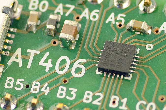
We decided to experiment with the ATtiny406 , hoping that in the future this microcontroller will replace the ATtiny45, which is currently used in PiWatcher - in our development, which allows, when such a need arises, to completely turn off or restart the Raspberry Pi. The ATtiny406 has 4 KB of flash memory, 256 bytes of RAM, the microchip can operate at 20 MHz without an external clock source.
One of the main differences between the new tinyAVR MCUs and older, well-known chips like the ATtiny85 is that the newer chips use the UPDI programming protocol. It only needs 3 pins for it to work, and 6 pins are needed for the ISP protocol used by old chips.
After a short study of the question, we learned that you can program tinyAVR with UPDI using a simple USB-to-Serial cable and resistor. We found this out thanks to the pyupdi Python tool , which suggested the following wiring diagram for uploading the firmware to the microcontroller.

Microcontroller connection diagram
▍Board Design for ATtiny406
We've created a minimalistic breakout board for the ATtiny406. This board can be powered by 5V from USB. Alternatively, you can apply a lower voltage of 3.3V to it using the dedicated VCC / GND pins. There is a place for a button and an LED on the board. To conduct experiments, we decided to build a 4.7 kOhm resistor into the board, which is required to use the UPDI protocol (this is resistor R2). As a result, we got the following board layout.

Board layout
▍Finished board
The finished breakout board turned out to be quite compact, it fits well into a small breadboard. The board schematics can be found here .
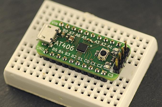
Backplane Mounted on Prototype Board
To program the ATtiny406, a USB-to-Serial cable is connected to the board using the pins on it.
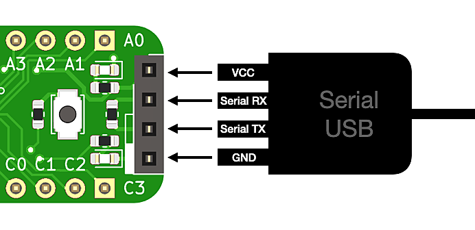
Cable connection diagram
The software part of the project
▍pyupdi
We installed pyupdi following the instructions from the project repository .
The USB-to-Serial cable was connected to the board using four UPDI pins. Our USB-to-Serial converter was seen in macOS as a
/dev/tty.usbserial-FTF5HUAV.
In order to make sure that the programmer recognizes the ATtiny406, you can execute a command similar to the following by editing the file path:
pyupdi -d tiny406 -c /dev/tty.usbserial-FTF5HUAV -i
If everything is configured correctly, then executing a command like this should result in the output of something like this:
Device info: {'family': 'tinyAVR', 'nvm': 'P:0', 'ocd': 'D:0', 'osc': '3', 'device_id': '1E9225', 'device_rev': '0.1'}
▍C compiler
It turned out that the usual avr-gcc compiler that can be installed on macOS using Homebrew does not allow setting ATtiny406 as a compilation target. Therefore, we decided to install avr-gcc provided by Microchip. To download the compiler, you have to create an account on the Microchip website, which is a bit annoying.

Downloading the compiler
After downloading the necessary materials presented in the form of an archive, we unpacked this archive into a separate folder. The path to the directory
binthat will be in this folder must be added toPATH. This will make the work easier in the future. Assuming that the compiler is stored in a folder$HOME/Src/avr8-gnu-toolchain-darwin_x86_64, youPATHcaneditit by adding the following command to the file.bash_profile:
export PATH=$PATH:$HOME/Src/avr8-gnu-toolchain-darwin_x86_64/bin/
The newest ATtiny MCUs are not supported by Microchip's avr-gcc compiler without additional configuration. To support them, you need to download the ATtiny Device Pack .
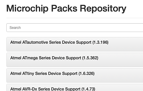
Downloading ATtiny Device Pack
As a result, we downloaded the package
Atmel.ATtiny_DFP.1.6.326.atpack(this file may be called differently, its name may include a different version number). Although the file extension is. atpack, this is actually a regular.ziparchive. We changed its extension to.zipand extracted the contents of the package to a folder$HOME/Src/Atmel.ATtiny_DFP.1.6.326, that is, to the same place where the compiler files were already.
▍Writing a C program
We wrote the following program, which, at a frequency of 1 Hz, blinks the LED connected to the B5 pin on our ATtiny board.
#include <avr/io.h>
#include <util/delay.h>

int main() {
    _PROTECTED_WRITE(CLKCTRL.MCLKCTRLB, 0); //   20 (,   0x02   2)

    PORTB.DIRSET = (1<<5);
    for (;;) {
        PORTB.OUTSET = (1<<5);
        _delay_ms(500);
        PORTB.OUTCLR = (1<<5);
        _delay_ms(500);
    }
}
This code is very similar to the LED blinking program written for familiar AVR microcontrollers. The first notable change is the use of structures to access MCU registers. For example, instead of referring to
PORTB, a call is made to PORTB.DIRSET.
Another change is represented by the frequency setting code
(_PROTECTED_WRITE(CLKCTRL.MCLKCTRLB, 0)). The new ATtiny406 runs at 3.33 MHz after a reboot, which corresponds to a base clock of 20 MHz, which is divided by 6. In order for the chip to run at full speed of 20 MHz, we clear the register CLKCTRL.MCLKCTRLB. Since this register must be protected from accidental changes, on the ATtiny406, a special software construction must be used to modify it. Fortunately, macros make this easier _PROTECTED_WRITE. You can read more about this.here .
If you compare this code with the one that is written for STM32 or SAMD21, it turns out to be much simpler.
▍ Makefile
Here we are using the following directory structure:
src/Atmel.ATtiny_DFP.1.6.326/- path to Microchip Device Pack.src/attiny406-test/- the folder in which, in the filemain.c, the above code is stored.
Compilation of the code from the directory
attiny406-test/can be performed with the following command:
avr-gcc -mmcu=attiny406 -B ../Atmel.ATtiny_DFP.1.6.326/gcc/dev/attiny406/ -O3 -I ../Atmel.ATtiny_DFP.1.6.326/include/ -DF_CPU=20000000L -o attiny406-test.elf main.c
The flag
-Oallows you to perform the optimizations necessary for the function calls to work successfully _delay_ms(). The same is true for a variable -DF_CPUwhose contents reflect the expected frequency of the chip. The rest of the parameters contain information about the location of the files for the ATtiny406, which we previously downloaded and extracted from the Device Pack archive.
To download the firmware to the MCU, you need to convert what you got to Intel HEX format. After that, you need to use pyupdi. We have created a simple
Makefile, automated solution to these tasks:
OBJS=main.o
ELF=$(notdir $(CURDIR)).elf
HEX=$(notdir $(CURDIR)).hex
F_CPU=20000000L

CFLAGS=-mmcu=attiny406 -B ../Atmel.ATtiny_DFP.1.6.326/gcc/dev/attiny406/ -O3
CFLAGS+=-I ../Atmel.ATtiny_DFP.1.6.326/include/ -DF_CPU=$(F_CPU)
LDFLAGS=-mmcu=attiny406 -B ../Atmel.ATtiny_DFP.1.6.326/gcc/dev/attiny406/
CC=avr-gcc
LD=avr-gcc

all:    $(HEX)

$(ELF): $(OBJS)
                $(LD) $(LDFLAGS) -o $@ $(OBJS) $(LDLIBS)

$(HEX): $(ELF)
                avr-objcopy -O ihex -R .eeprom $< $@

flash:  $(HEX)
                pyupdi -d tiny406 -c /dev/tty.usbserial-FTF5HUAV -f attiny406-test.hex

read-fuses:
                pyupdi -d tiny406 -c /dev/tty.usbserial-FTF5HUAV -fr

clean:
                rm -rf $(OBJS) $(ELF) $(HEX)
To compile the code, just run the command
make. Downloading the code to the microcontroller is performed by the command make flash. The one presented by us Makefilecan be, if necessary, revised.
Outcome
The new TinyAVRs are as easy to program as previous generations of MCUs. The main thing is to find the right tools. If you have any tips for programming AVRTiny, please share them with us on Twitter or in the comments below.
Are you planning to use the new TinyAVR in your projects?