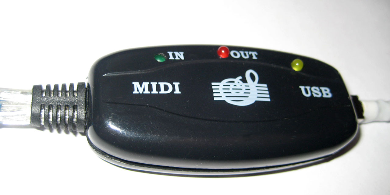
 Fig.1 Russian-Chinese-American MIDI to USB converter. Photo by the author.
People love music. Many people know how to play musical instruments. And some try to improvise and even compose music. Electronic musical instruments can be connected to your computer for more creative possibilities. This seems to be a simple matter, but most of the cheap Chinese USB-MIDI adapters perform mediocre. Who cares how I made my MIDI2USB adapter, I invite you to read
Formulation of the problem
A couple of years ago my nephew, who is studying music, started improvising and composing music. I wanted his work not to be lost, but I managed to record his musical studies only on a dictaphone. The quality of this recording was unsatisfactory. I wanted to record notes directly in Cubase or MuseScore and then edit them. For this I decided to buy a Chinese USB-to-MIDI adapter (converter).
Anecdote in the subject
:
— , !
— , ?
— !
— , !
— , ?
— !
This adapter cable is cheap and doesn't work well. Data transfer from the synthesizer (electric piano) to the computer does not work. If you play with one finger, you can record several notes, and when you take a chord or play scales, the adapter freezes and turns into a brick. Another direction, i.e. transferring data from the computer to the synthesizer works well. Similar stories can be found in the reviews of many buyers.
Ways to refine the Chinese adapter
There are many discussions on the Internet on how to improve or modify the Chinese adapter. In some versions of this adapter an optocoupler is provided, but not soldered, which provides galvanic isolation between the computer and the synthesizer. Alas, in my case, the revision was difficult, because instead of an optocoupler, two NPN transistors are installed. Note that the MIDI standard directly specifies the use of an opto-isolator, for example, PC900V or 6N138. Optocouplers H11L1M (DIP-8) or H11L1SM (SO-6) have similar characteristics. Other components with suitable parameters can be used.
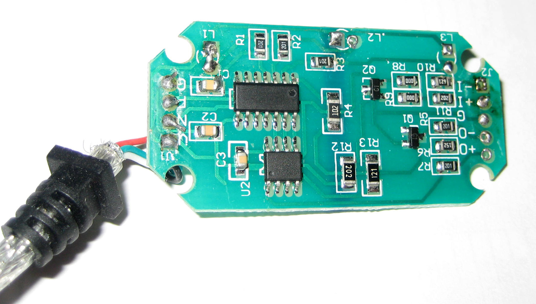
Fig. 2. Chinese adapter in the process of dismantling. Photo by the author.
The photo shows that there is enough space in the case to accommodate the opto-isolator and related elements. Some craftsmen solder the existing components and install an opto-isolator with a "body kit" in their place. Obviously, this operation requires not only knowledge, but also good hand motor skills.
But it is not enough to provide optical isolation between the musical instrument and the computer. A precision crystal oscillator or resonator is also required to ensure that the serial UART is clocked in accordance with the MIDI standard. The Chinese adapter I bought lacks not only an optocoupler, but also a quartz resonator. Of course, there are microcircuits in which clocking units are calibrated at the factory, but there is nothing like this. In general, the performance of this Chinese product is low. There are adapters built on the CH345 chip - a USB to MIDI converter in an SSOP-20 package, but this is not my case. The CH345 microchip has hardware USB tags Vendor ID: 1a86, Product ID: 752d. However, any "left-hand" microcircuit can (and does) give out the same identifiers and can even "pretend" to be anything.
The last small flaw that I found in the Chinese adapter is the software (firmware). More precisely, this is a small buffer size for endpoints, only 8 bytes each. This is enough to transmit the pressed notes, because the MIDI message via the USB interface consists of 4 bytes (cable number, command number and 2 data bytes). But any extensions, for example SysEx, can be larger.
After a while, I bought another adapter cable, which was called “Professional USB MIDI Interface”. This adapter was significantly more expensive and performed significantly better, but still with errors. This was manifested in the fact that after a few minutes of playing the synthesizer, he suddenly began to miss keystrokes, or vice versa - did not perceive the release of the key. I was disappointed with the results of the Chinese adapters and decided to follow the advice: "If you want to do something well, then do it yourself."
Hardware part
First, it was necessary to think over the scheme of the future device and study the experience of other engineers. The existing adapter looked very good on the outside, so I decided to use a case, LEDs and shielded cables from it. Moreover, in Moscow, MIDI cables are more expensive than a ready-made Chinese adapter. I pulled out the Chinese board, measured its dimensions and began to study the MIDI standard and successful MIDI projects in the public domain.
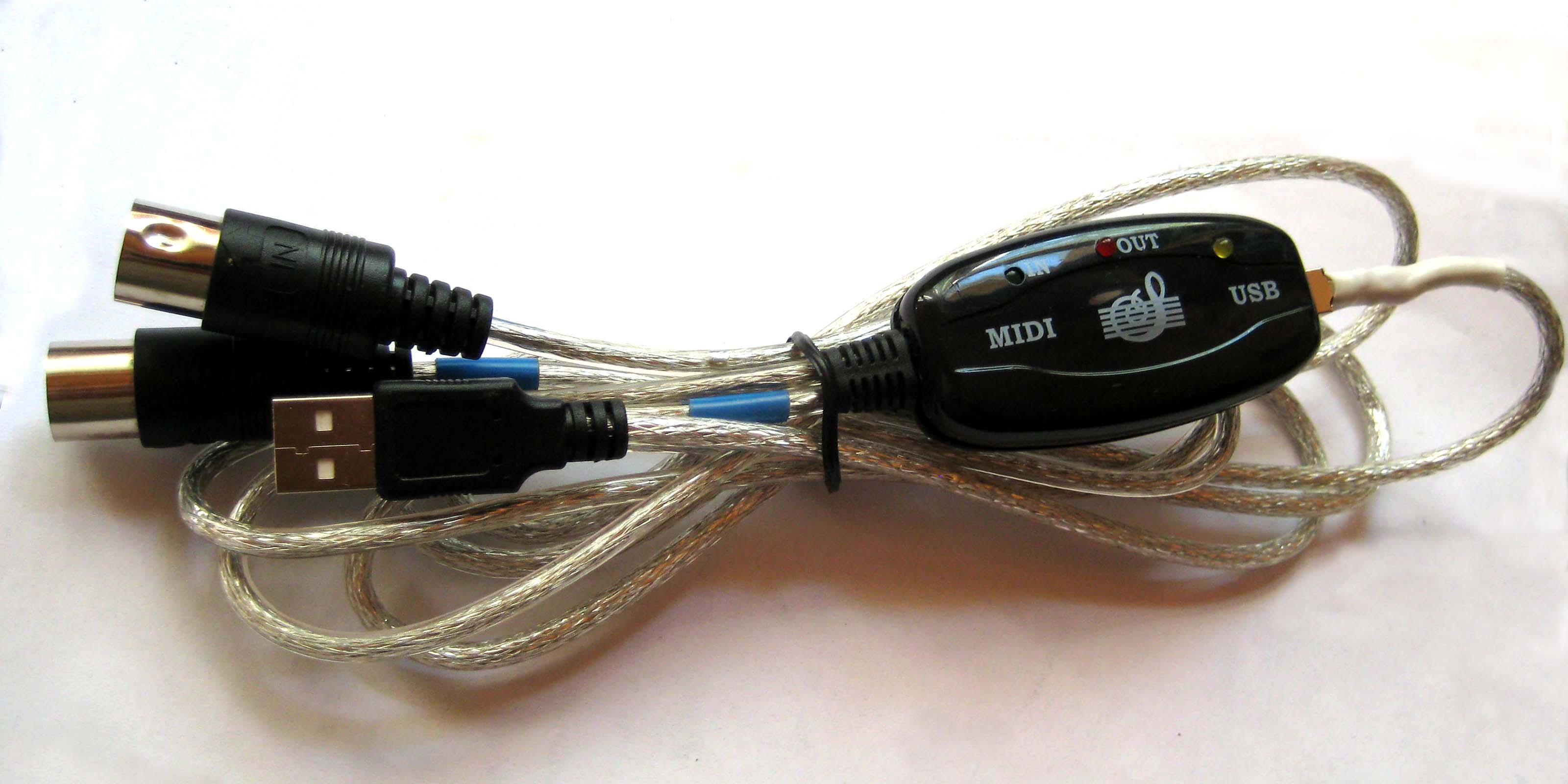
Fig. 3 USB-MIDI adapter in case and with cables.
At the time of this writing, I know of several interesting projects:
- Diagram from the documentation for the CH345 chip from Nanjing Qinheng Microelectronics.
- Old projects on Atmega microcontrollers with software implementation of the USB protocol. They use Low Speed mode, which is deprecated and not supported in Windows 7.
- MIDIUSB library for Arduino boards with hardware support for USB interface (Atmega32u4, Cortex-M), as well as Maple, etc.
The electrical schematic diagrams in all projects contain many sample fragments based on the recommendations of the MIDI standard . Therefore, it remained to choose a microcontroller with support for USB Full Speed mode, find a PC900V optocoupler and a DIN-5 (MIDI) socket on sale.
Board layout

The heart of my MIDI2USB adapter is an 8-bit EFM8UB20F64G microcontroller from Silicon Laboratories. I really like it and use it wherever I can. This controller is the successor (after rebranding) of the C8051F380 controller, which replaced the legendary C8051F320 - a successful development of Cygnal, which was bought by SiLabs in 2003.
I will list my arguments in favor of the EFM8UB20F64 microcontroller:
- ease of software development, which is expressed in the presence of fast and easy-to-use GPIO, SPI, UART, USB, PCA;
- improved 8051-core (1-2 cycles per instruction, 48MIPS), frequency change "on the fly";
- built-in voltage regulator, output tolerance to + 5V, current up to 100 mA;
- built-in accurate clock generator with calibration from USB-host (± 0.25%);
- availability of USBXpress, VCPXpress, USB Device API libraries and examples for quick start;
- pure errata.
It's a pleasure to program this controller, because there are few registers and you can concentrate on solving an applied problem. Alas, arithmetic operations (especially 32-bit ones) are slow, but otherwise EFM8 is good. Developing software for USB devices is not an easy task. And here the main advantage of SiLabs controllers is the USBXpress, VCPXpress, USB Device API libraries. Even Texas Instruments uses C8051F320 controllers in their SmartRF boards.
The optocoupler is the second most important component in the adapter. I decided to take the Sharp PC900V because it is exactly what is specified in the recommended MIDI specification diagram. The peculiarity of this optocoupler is fast on and off times (1μs and 2μs), as well as the presence of a digital output. But there are also disadvantages - the large size of the microcircuit (7x10mm) and burnout by 50% after 5 years of operation. The dimensions of the optocoupler did not allow marking all the components on one side of the board. I also didn't want to give up the MIDI connector, which took up a lot of space.

Fig. 4 Rear side of the board with PC900V optocoupler and LEDs. Photo by the author.
The output stage is assembled according to the recommended standard scheme on a logic chip 74LVC2G04, consisting of two inverters. The main purpose of this component is to convert logic signal levels from 3V => 5V and provide an output current of at least 10 mA.
Another anecdote
:
- , , , , , …
. :
— - ?
— , !
- , , , , , …
. :
— - ?
— , !
The rest of the components perform auxiliary functions and do not significantly affect the operation of the device. Resistors, capacitors, diodes and LEDs can be replaced reasonably. Instead of a mini-USB connector, you can put a micro-USB or make a pin connector for soldering the cable, as the Chinese do. The MIDI connector takes up a lot of space and does not fit into the case, so it is only used in the adapter version without a case. The MIDI-IN and MIDI-OUT signals are routed to the pin header for cable wiring. In general, the location of the LEDs and connectors should be adjusted for their optimal placement in the case.
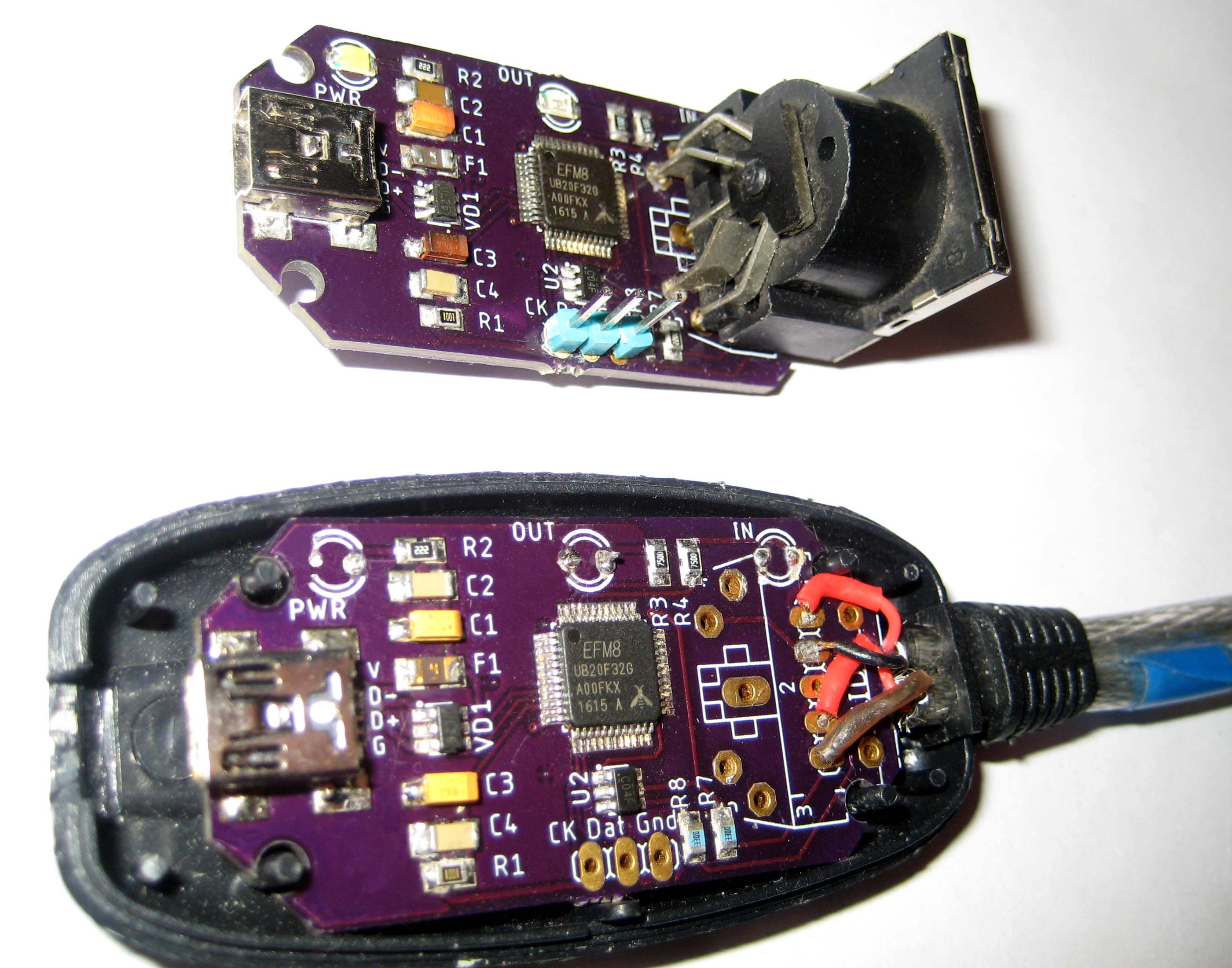
Fig.5 Debug and boxed versions of the MIDI2USB adapter. Photo by the author.
The total consumption current does not exceed 50 mA. It consists of the following parts:
- microcontroller, 15mA;
- three LEDs, 15mA (3x5mA);
- microcircuit 74LVC2G04, 10 mA;
- optocoupler PC900V, 10 mA.
The 2-layer PCB was made by Americans at OSH Park , 1.6mm thick, 0.035mm copper, FR-4 material.
Software part
Creation of software for equipment is an important and crucial stage of development. Fortunately, all modern operating systems have drivers for USB MIDI devices. The task is reduced and you only need to write the firmware for the adapter.
I usually use Keil uVision PK51 in conjunction with Configuration Wizard 2, sometimes IAR Embedded Workbench, and very rarely SiLabs Simplicity Studio. Each environment has advantages and disadvantages. In this project I decided to use IAR because I wanted to have "C with classes". In addition, the IAR compiler provides access to all bits of the system registers. For example, P2_bit.B0 = 1; or PCA0MD_bit.WDTE = 0;
There is no need to use the "magic constants" or multi-level bit expressions that are full of CMSIS or "SI_EFM8UB2_Register_Enums.h". Alas, all this functionality is declared in the ioEFM8UB20F64G.h file, which turned out to be incompatible with the si_toolchain.h libraries (for example, the macro B0..B3). I did not translate the project into Keil uVision PK51, but simply wrote compatible C code for all development environments.
The project code is divided into several functional parts
- The file "main.c" contains the entry point, declarations of global variables, a call to initialize peripherals, and the main program loop.
- The file "init.c" contains the settings for clocking, ports, UART and its interrupts.
- The descriptors.c file contains USB descriptors for the Audio Class device.
- The file "midi.c" contains two functions for converting MIDI messages to USB events and vice versa. A state machine is used.
- The file "usbconfig.h" contains macros and definitions (#define) for configuring the modes of operation of the USB Device API library.
Let's take a look at the main () function with the ports, peripherals, and the main loop.
int main( void )
{
	WDT_Init();                             // Disable WDTimer (not used)
	PORT_Init();                            // Initialize ports (UART, LEDs)
	SYSCLK_Init();                          // Set system clock to 48MHz
	UART0_Init();                           // Initialize UART0 @31250, 8-N-1
	USBD_Init( &usbInitStruct );            // Initialize USB, clock calibrate
	LED_IN  = 1;                            // Blink LED
	LED_OUT = 1;                            // Blink LED
	IE_EA   = 1;                            // Global enable IRQ

	while(1)
	{
		//--- MIDI => USB
		if( nMidiCount > 0 )
		{
			IE_EA  = 0;                     // Begin: Critical section
			if( USB_STATUS_OK==USBD_Write(EP1IN,aMidiBuffer,nMidiCount,false) )
			{
				nMidiCount = 0;             // Reset MIDI data byte counter
			}
			IE_EA  = 1;                     // End of: Critical section
			LED_IN = 0;                     // Turn off input LED
		}

		//--- USB => MIDI
		if( nUsbCount )
		{
			uint8_t i;
			LED_OUT = 1;                    // Turn on Led on New packet
			for(i = 0; i < nUsbCount; i++)  // Process every data byte
			{
				USB2MIDI( aUsbBuffer[i] );  // Convert USB packet into MIDI
			}
			nUsbCount = 0;                  // Reset counter
			USBD_Read(EP2OUT, aUsbBuffer, sizeof(aUsbBuffer), true);
			LED_OUT = 0;                    // Turn off Led, when done
		}
	}
}
SiLabs' library for USB devices consists of a set of subroutines that are compiled and included in the project depending on the settings in the “usbconfig.h” file. This is very reminiscent of the "libusb, V-USB" library found in the code for microcontrollers from Atmel (now Microchip). It should be noted that SiLabs has a good and convenient library from the point of view of a programmer.
Descriptors (descriptors) of the device, configuration and interfaces play an important role in the operation of any USB device. Using these descriptors, the device informs the host (computer) about its requirements, capabilities, parameters, etc. The function for handling descriptor requests is usually found in every USB library, and the programmer is only required to correctly fill in the data structures containing these descriptors.
Code with descriptors
SI_SEGMENT_VARIABLE
(usbDeviceDesc[], const USB_DeviceDescriptor_TypeDef, SI_SEG_CODE) =
{
	USB_DEVICE_DESCSIZE,               // bLength, 18 bytes
	USB_DEVICE_DESCRIPTOR,             // bDescriptorType, 1
	htole16(0x0110),                   // bcdUSB Ver, 1.10
	0x00,                              // bDeviceClass, 0 for Audio
	0x00,                              // bDeviceSubClass, 0 for Audio
	0x00,                              // bDeviceProtocol, 0 for Audio
	SLAB_USB_EP1IN_MAX_PACKET_SIZE,    // bMaxPacketSize0, 64 bytes
	htole16(0x1209),                   // idVendor, Free GPL (SiLabs 0x10C4)
	htole16(0x7522),                   // idProduct
	htole16(0x0100),                   // bcdDevice, 1.00
	0x01,                              // iManufacturer string
	0x02,                              // iProduct string
	0x03,                              // iSerialNumber (no serial string)
	0x01                               // bNumConfigurations
};
All descriptors, topology and terminology are detailed and detailed in the "Universal Serial Bus Device Class Definition for MIDI Devices" standard . And for a quick start and immersion in the topic, it is enough to study the information provided by the "usbview.exe" programs from the Windows Driver Kit 7600 or "USB Descriptor Dumper" . Something you can even copy to your program.

Fig.6 Information about descriptors in the program "usbview.exe"
Descriptors and corresponding arrays and structures are located in the flash memory of the microcontroller (code segment), because these data do not change (constants). Storing constants in flash memory is a typical programming trick that allows you to save RAM.
Pay attention to the Vendor_ID and Product_ID fields in the device descriptor structure. This is a pair of numbers to uniquely identify the USB device. To get such a number for your device, you need to pay money to the USB-IF organization or send a request to the owner of the existing Vendor_ID (microcontroller manufacturer) and get the Product_ID. And you can, for example, how the Chinese use other people's most suitable VID & PID. For open source projects, there is an option to get a free Product_ID .
Another point to pay attention to when developing USB devices of the MIDI Streaming audio class are connectors (Jack). Connectors are imaginary (virtual) entities for describing topology and connections between a device and a host. They are input (In Jack) and output (Out Jack), internal (Embedded) and external (External). Each connector has a unique Jack_Id (number from 0 to 15). The output connectors contain the Source Id number, i.e. connector number for connection. Finally, audio end-points (EP) work on top of the formed channels (input and output streams). These are almost ordinary Bulk EPs that have connector binding information in their descriptors.

Figure: 7 Jacks and virtual streams to USB (MIDI class).
MIDI Jack Descriptors
	// EMB:  IN Jack #1 <-----> EXT: OUT Jack #4
	// EMB: OUT Jack #3 <-----> EXT:  IN Jack #2

	//--- Class-Specific MS Interface Header Descriptor, p.40
	USB_MIDI_INTERFACE_DESCSIZE,       // bLength, 7 bytes
	USB_CS_INTERFACE_DESCRIPTOR,       // bDescriptorType, 0x24
	MIDI_CS_IF_HEADER,                 // bDescriptorSubtype, 0x01
	0x00,                              // bcdADC(LSB)
	0x01,                              // bcdADC(MSB), 0x0100 (version)
	0x41,                              // wTotalLength(LSB), 65 bytes
	0x00,                              // wTotalLength(MSB)

	//--- MIDI IN JACK EMB(it connects to the USB OUT Endpoint), p.40
	USB_IN_JACK_DESCSIZE,              // bLength, 6 bytes
	USB_CS_INTERFACE_DESCRIPTOR,       // bDescriptorType, 0x24
	MIDI_CS_IF_IN_JACK,                // bDescriptorSubtype, 0x02
	MIDI_JACK_TYPE_EMB,                // bJackType, 0x01 (embedded)
	1,                                 // bJackID, #1
	0,                                 // Jack string descriptor, unused
	//--- MIDI IN JACK EXT, p.40
	USB_IN_JACK_DESCSIZE,              // bLength, 6 bytes
	USB_CS_INTERFACE_DESCRIPTOR,       // bDescriptorType, 0x24
	MIDI_CS_IF_IN_JACK,                // bDescriptorSubtype, 0x02
	MIDI_JACK_TYPE_EXT,                // bJackType, 0x02 (external)
	2,                                 // bJackID, #2
	0,                                 // Jack string descriptor, unused

	//--- MIDI OUT JACK EMB (connects to IN Endpoint), p.41
	USB_OUT_JACK_DESCSIZE,             // bLength, 9 bytes
	USB_CS_INTERFACE_DESCRIPTOR,       // bDescriptorType, 0x24
	MIDI_CS_IF_OUT_JACK,               // bDescriptorSubtype, 0x03
	MIDI_JACK_TYPE_EMB,                // bJackType, 0x01
	3,                                 // bJackID
	1,                                 // bNrInputPins
	2,                                 // baSourceID, this <=> Jack #2
	1,                                 // baSourcePin
	0,                                 // iJack, unused
	//--- MIDI OUT JACK EXT, p.41
	USB_OUT_JACK_DESCSIZE,             // bLength, 9 bytes
	USB_CS_INTERFACE_DESCRIPTOR,       // bDescriptorType, 0x24
	MIDI_CS_IF_OUT_JACK,               // bDescriptorSubtype, 0x03
	MIDI_JACK_TYPE_EXT,                // bJackType, 0x02
	4,                                 // bJackID
	1,                                 // bNrInputPins
	1,                                 // baSourceID, this <=> Jack #1
	1,                                 // baSourcePin
	0,                                 // iJack, unused
Data exchange in a USB MIDI class audio device consists in the transmission of 32-bit packets (USB-MIDI Event Packet). Messages of 1, 2 or 3 bytes are received from the MIDI device. When transferring over USB, a head byte with a cable number and command code is added to these bytes. If the packet is less than 4 bytes, then it is padded with 0. In the current firmware version, I do not fill with zeros up to the 32-bit border. It works. The question remains open.
For example, in cable # 1, the command to press the Note On key (transmission time 960us) is converted into the following packet:
MIDI: 0x90 0x60 0x7f => USB: 0x19 0x90 0x60 0x7f
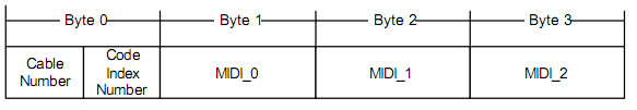
Fig. 8 Scheme of the USB-MIDI Event Packet from the USB specification.
typedef union
{
	struct PACKET
	{
		uint8_t  cable : 4;            // Cable Number (we use #0)
		uint8_t  cin   : 4;            // Code Index Number (cmd: 0x08)
		uint8_t  cmd;                  // MIDI command (status byte)
		uint8_t  data1;                // MIDI data byte #1
		uint8_t  data2;                // MIDI data byte #2
	};
	uint8_t buffer[sizeof(struct PACKET)];
} MIDI_EVENT_PACKET;
Direct and reverse conversion is performed by the MIDI2USB () and USB2MIDI () functions . In these functions, a state machine is used, when, as input data arrives, the function goes from the idle state (IDLE) to the state of receiving commands (STATUS), and then to the state of receiving data (DATA), and, finally, sending data with a return to its original state expectations.
In the MIDI protocol, the data bytes are essentially 7-bit (0..127). They always have the most significant 8th bit set to 0. Commands (status bytes), on the contrary, always come with the most significant bit set to 1, i.e. have values from 128 to 255.

Fig. 9 Types of bytes in the MIDI protocol.
Joke about the digit capacity of numbers
:
— , ?
— H, .
— , 11-22-33?
— H, 11-22-34.
— H ! , !
— , ?
— H, .
— , 11-22-33?
— H, 11-22-34.
— H ! , !
All schemes and source codes, as well as the finished firmware are in my git repository . MIT license.
Software
After installing the board, the microcontroller should be programmed. To do this, you can use either a proprietary / clone SiLabs C2 Debug Adapter, or J-Link v10 + (with EFM8 support), or a bootloader flashed at the factory (revision Rev-B), or, finally, Arduino with an appropriate script. For checking and debugging MIDI messages, MIDI-OX is a great help .
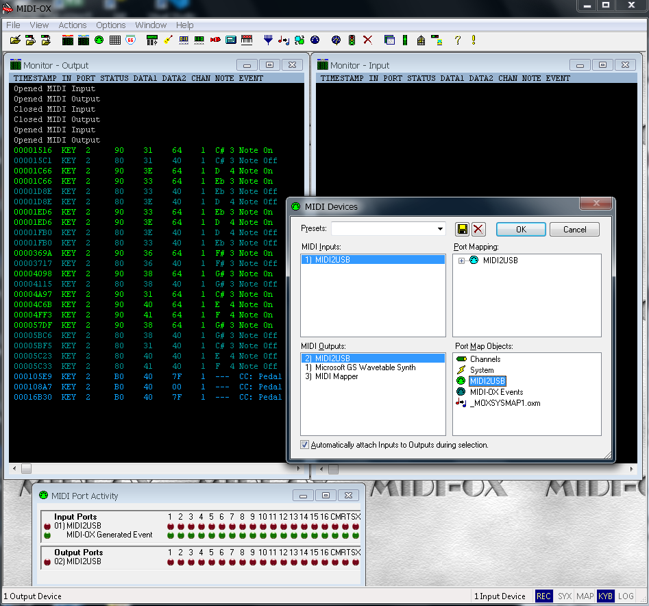
Fig.10 Interface of the MIDI-OX program.
If you work with Cubase, you should install the Asio drivers, because when using DirectSound and DirectInput, there is a delay between pressing a key and playing the note. Latency is unrelated to hardware and is a feature of the OS implementation. In general, the device performs its functions perfectly with the Casio CDP-100 instrument.
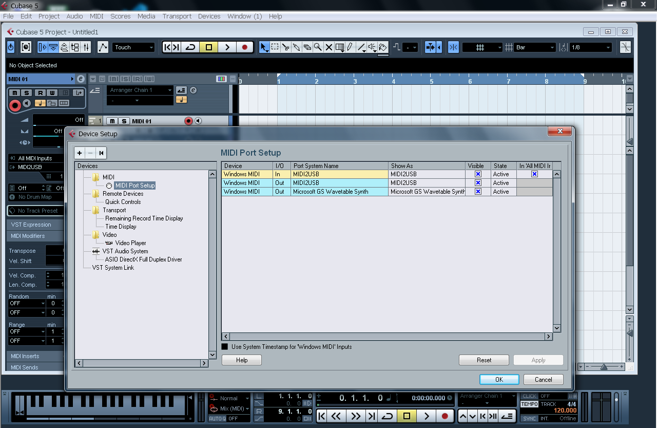
Fig. 11 Cubase 5 interface.
The experimental firmware generated the largest possible stream of notes and other MIDI commands. The cacophony was terrible, but everything worked as intended. And with MuseScore 3.2 you can record and play mid files.
Last joke
1990-. . — . . :
— , !
— , ! — !
— ! !
— … . !
— ! !
. . , , , … . , . :
— , , ?
— , !
— , ! — !
— ! !
— … . !
— ! !
. . , , , … . , . :
— , , ?
Results of work
The adapter works! It seems I managed to make a good MIDI to USB converter. For my device, I used a case, some parts and cables from a Chinese adapter. The mini-USB connector ended up deep in the case and had to redo the USB cable and work with a file. The LEDs, although at an angle, fit tightly into the holes. The board needs to be modified for the Chinese case.

Figure: 12. Compact disassembled mini-USB plug.
The decision to use the 8-bit EFM8UB20 microcontroller may seem controversial to some. There are other options and controllers, of course. An alternative way is to choose a purely hardware solution on the CH345 converter and make the device according to the reference circuit recommended by the Chinese. But my version is universal, because allows you to change the firmware, add the desired functionality or fix found errors. In the end, I gained knowledge, experience and moral satisfaction from the finished project. And finally, I finished my article and you finished reading it.
useful links
- USB standard for MIDI devices
- MIDI Specification 1.0
- Comparison of USB-MIDI adapters
- Chip CH345T
- Listen to the works of the young composer
- Author's open projects
Thank you for attention.