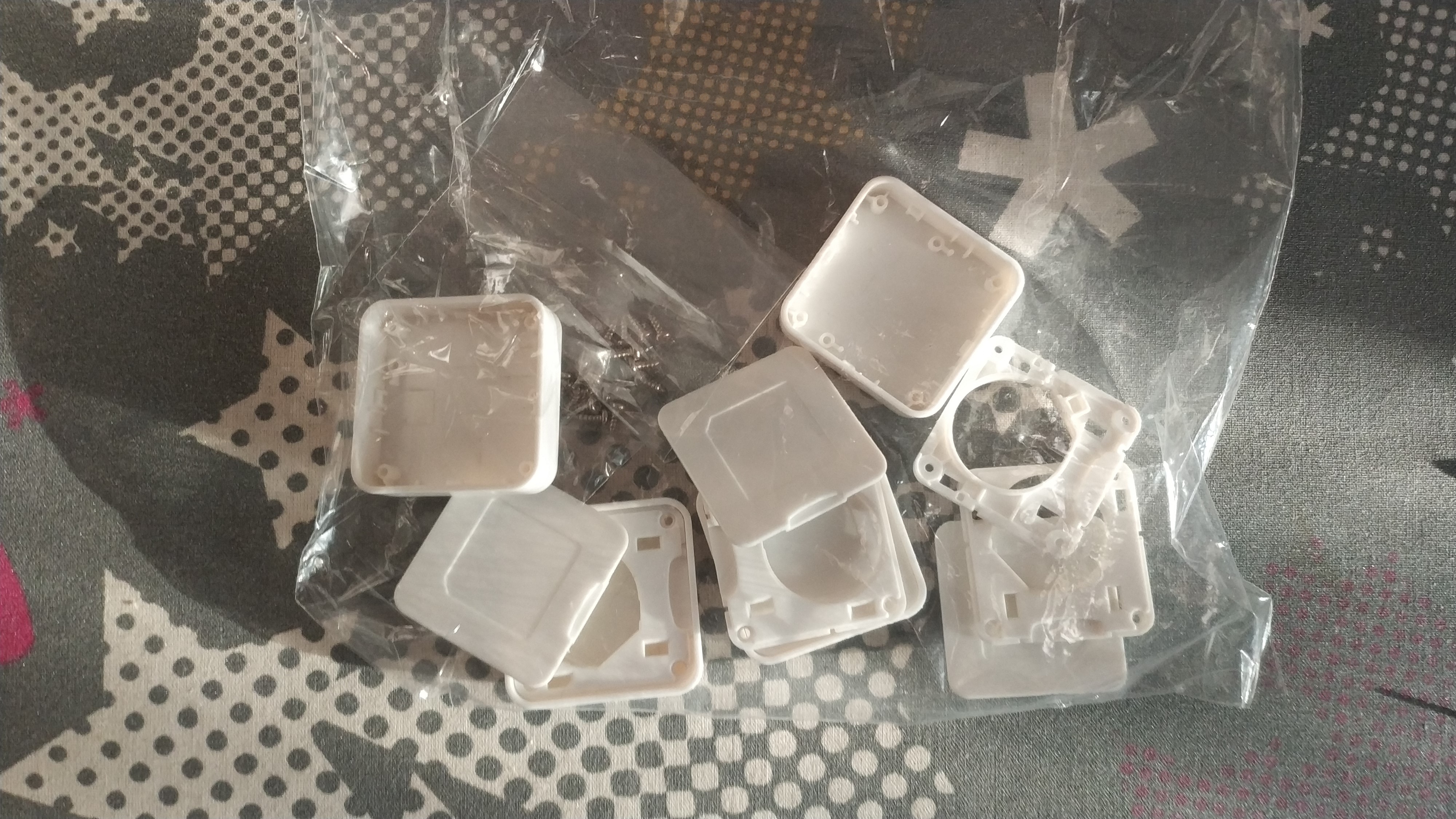
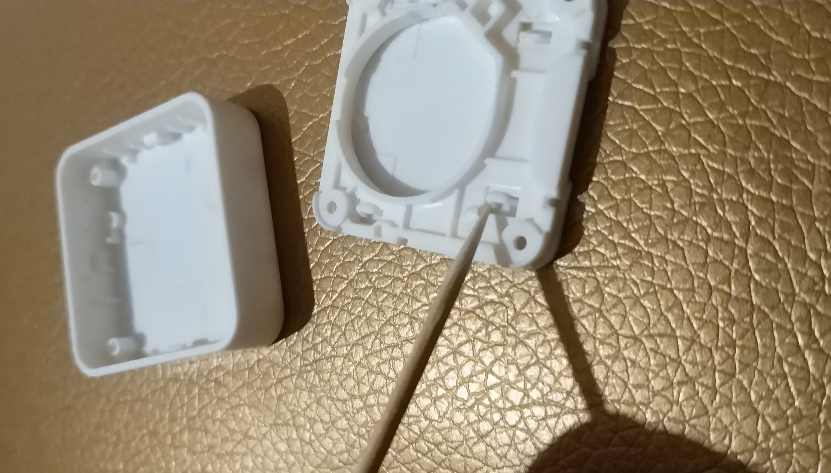
The history of this project began with the corpus, it sounds like a fool, but this is how this project began. The case was purchased on the Aliexpress website, it should be noted that the plastic molding quality of this case is excellent. After a short correspondence with the seller, a drawing was sent to the post office and this project began.
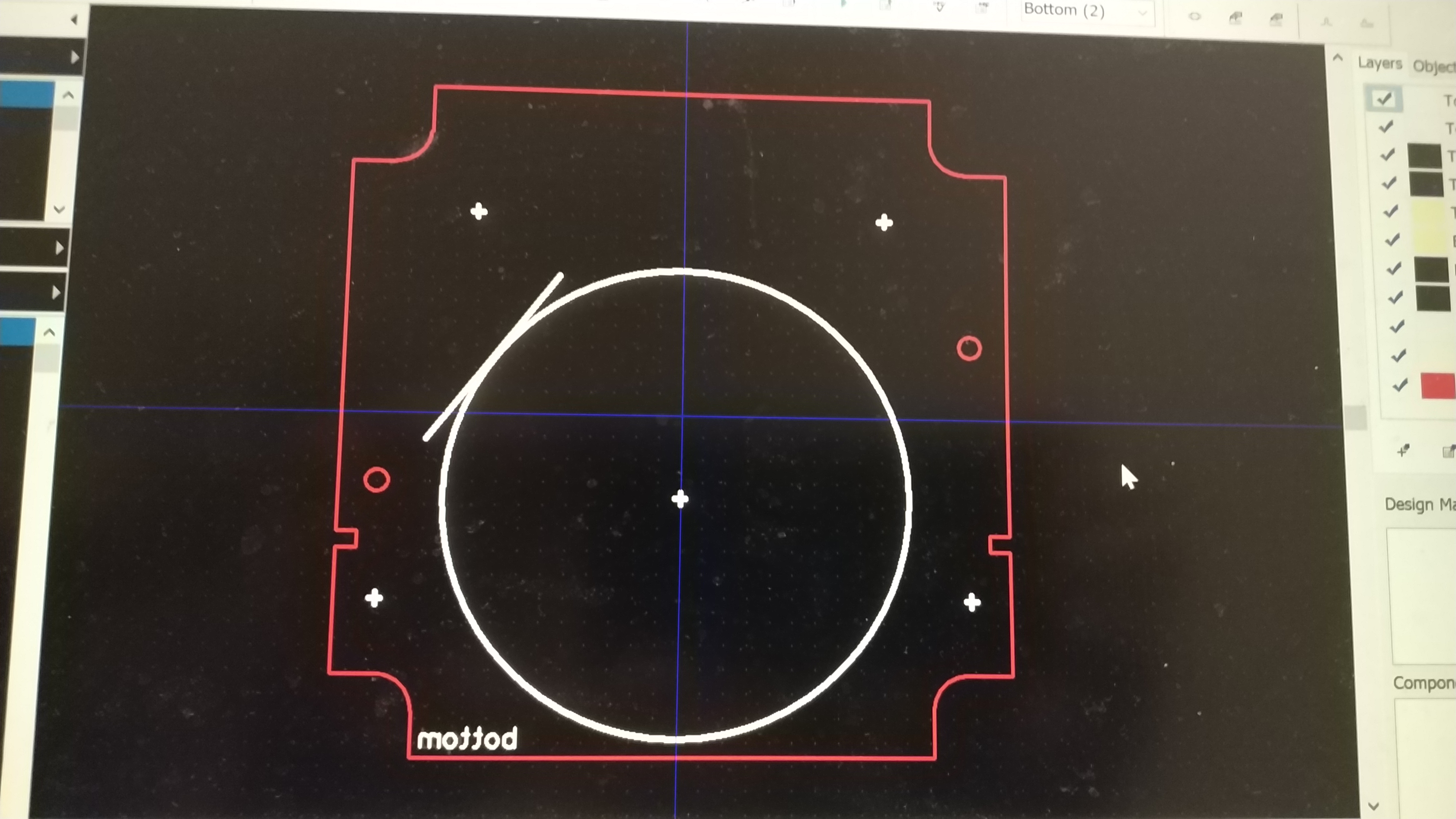
The drawing itself was very poorly dimensioned and half of the measurements for the boundaries, cutouts and technological holes of the future printed circuit board had to be done using a caliper. Having received all the internal dimensions of the case, it became clear that the radio chip would have to be “wired” directly on the PCB, since the height from the top of the PCB to the inner surface of the case was 1.8 mm, and the minimum height of the finished average radio module is usually 2 mm (without the screen).
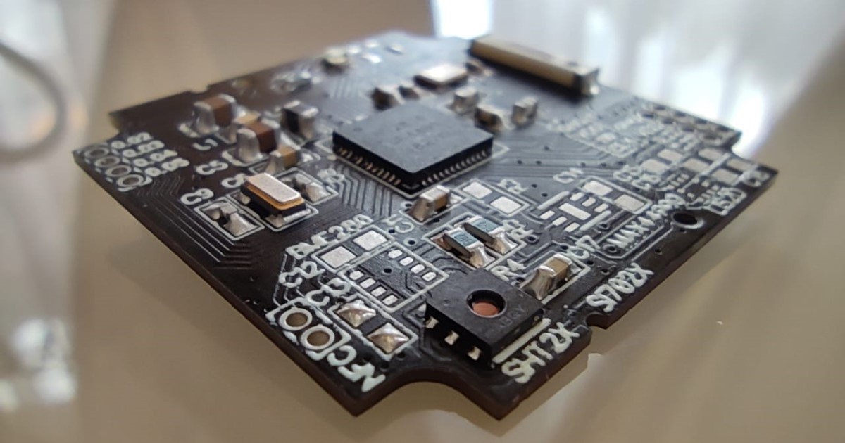
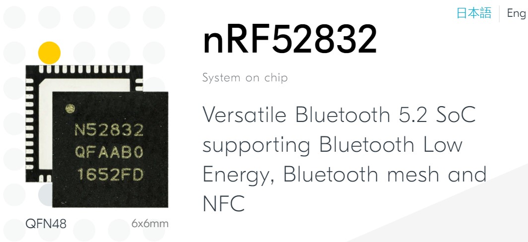
The nRF52 SoC in the QFN48 package was chosen for the sensor. Nordic has three options in this nRF52 series: nRF52810, nRF52811 (new), nRF52832. Chip parameters: 64 MHz Cortex-M4, 2.4 GHz transceiver, 512/256 KB Flash, 64/32 KB RAM for nRF52832 and 192 KB Flash, 24 KB RAM for nRF52810, nRF52811, multi-protocol chips, support Bluetooth Low Energy, Bluetooth mesh, ESB, ANT, and nRF52811, in addition to the above, also Zigbee and Thread, as well as Bluetooth Direction Finding.
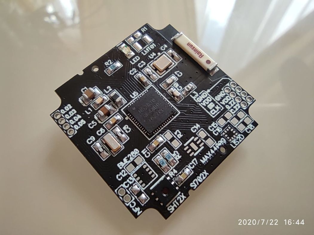
The sensor itself decided to make it multi-sensor, so that it could be used for different tasks. For this reason, the layout of the chip had to be made as compact as possible, taking into account that the minimum dimensions of the components should not be less than 0603, so that the device could be soldered manually. After the chip was wired on the board, I started selecting sensors. The main thing I was guided by during the selection is the dimensions of the sensor body and the possibility of soldering the sensor at home with a minimum set of equipment (soldering iron and hair dryer).
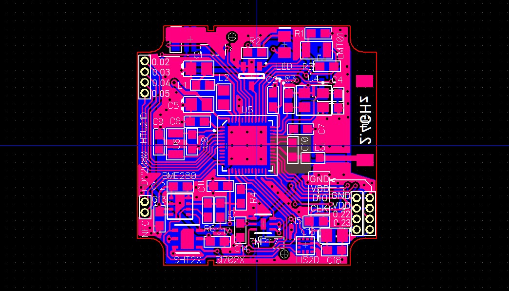
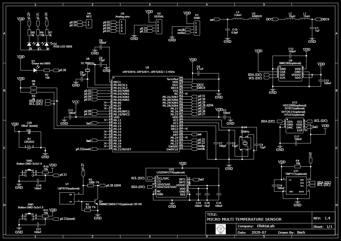
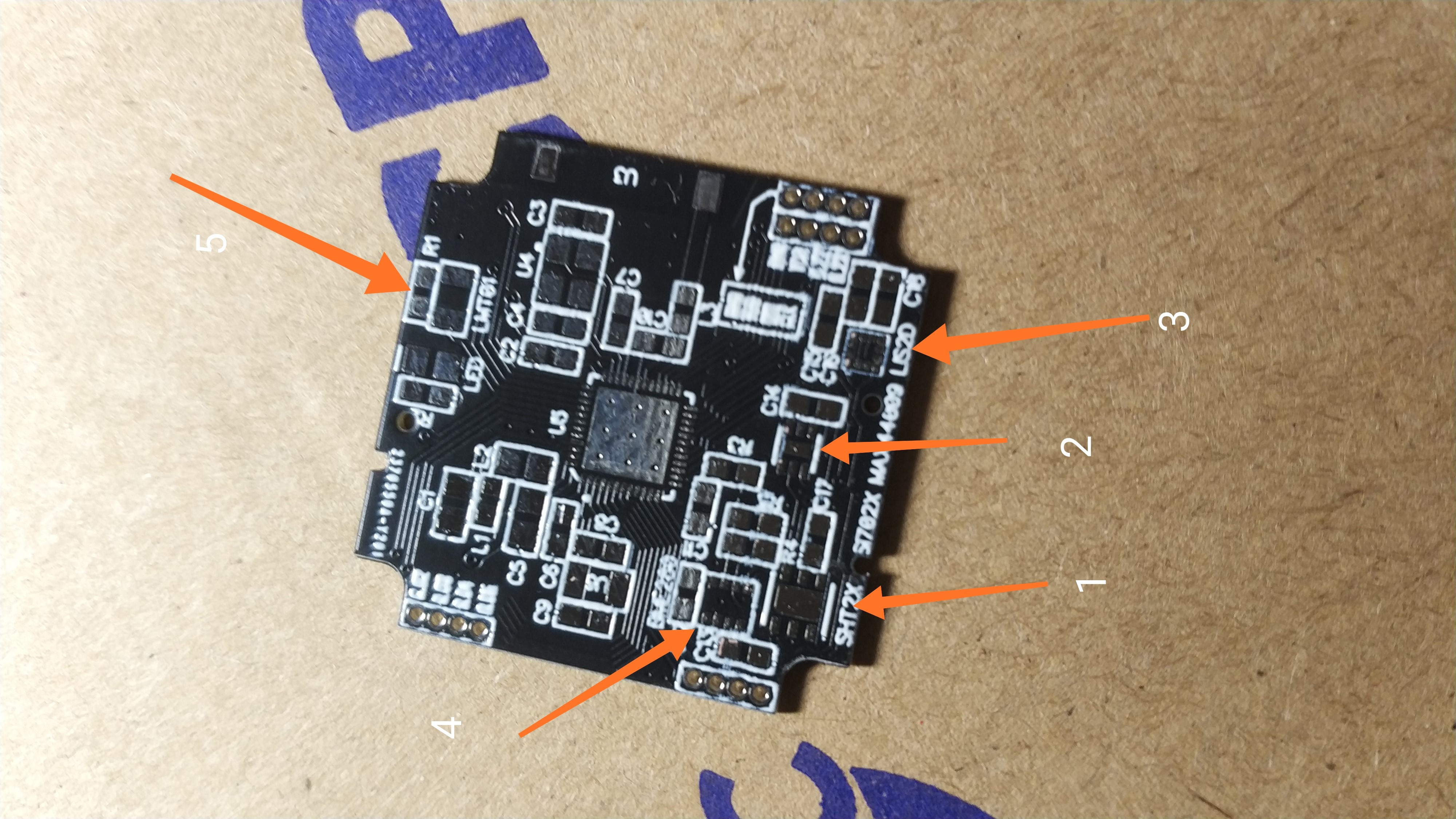
The following sensors were selected for the sensor: SHT20, SHt21, Si7020, Si7021, HTU21D (temperature and humidity sensor), all these sensors have the same body and the same pins, HDC2080 (temperature and humidity sensor) also has a similar body as before listed but has an additional interrupt output, more energy efficient, BME280 (temperature, humidity and pressure sensor), LMT01 (temperature sensor), TMP117 (high precision temperature sensor), high energy efficiency, interrupt output, setting upper and lower temperature limits, LIS2DW12 (accelerometer ) high energy efficiency, one of the best in its segment or LIS2DH12.
Also in the first version of the sensor, there was a reed switch in the list, but in subsequent revisions it was excluded, since there was not enough space for a reed switch 1.6 cm in size with a glass bulb, and I split a couple of such sensors by installing the finished board in the case, also because of the square the type of case and its small height, the device was not very suitable for the role of a magnetic sensor for opening and closing.
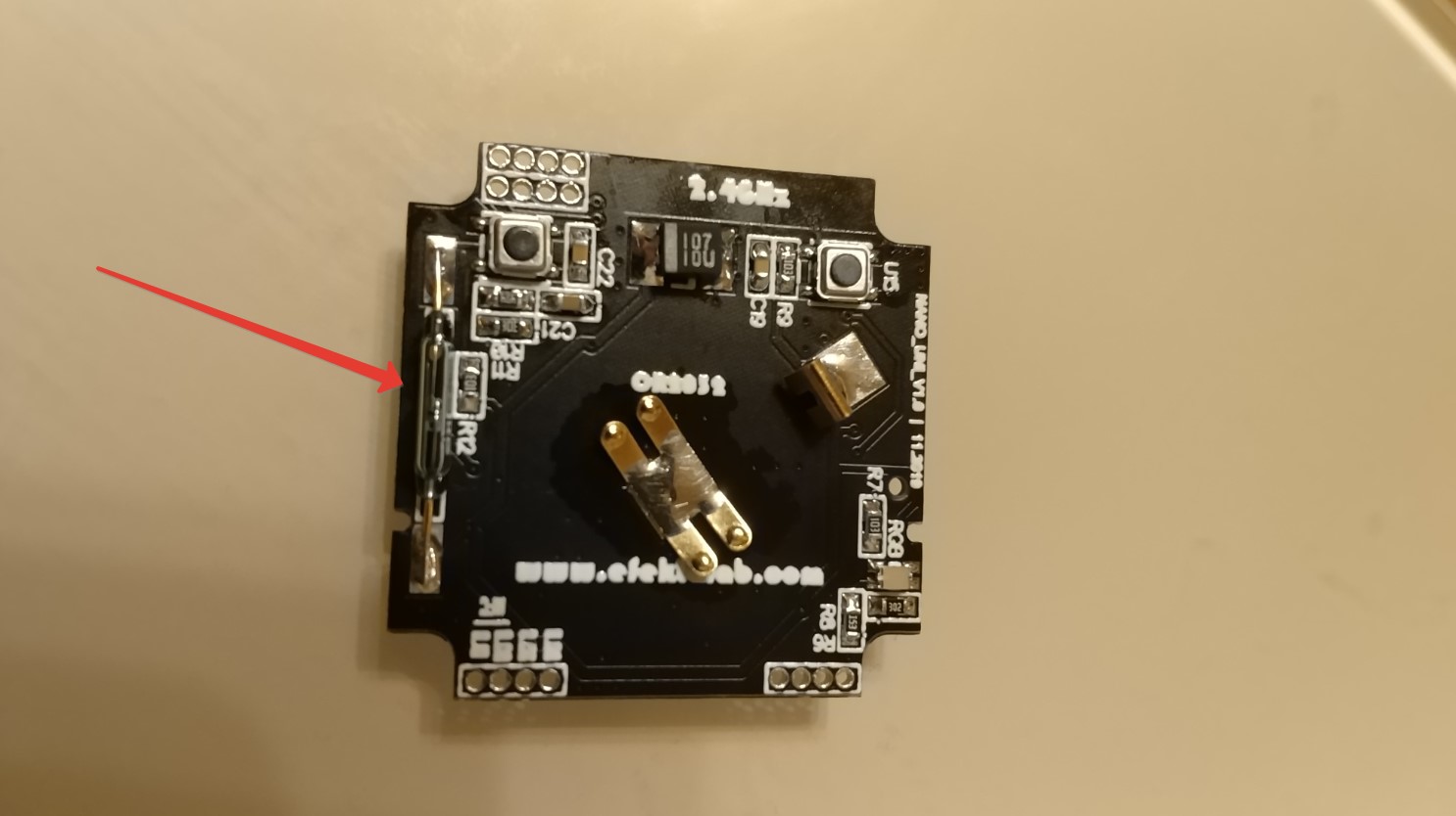
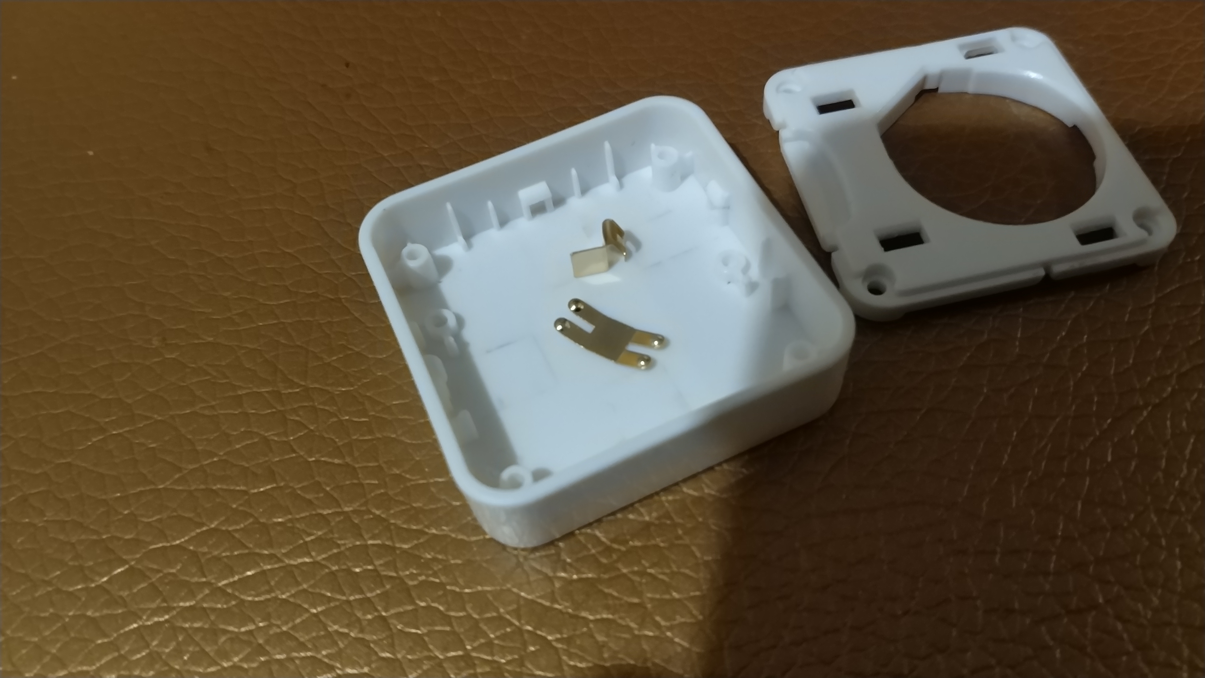
In addition to the sensors, the sensor has 2 LEDs, one of which is rgb located on the underside of the sensor. Two smd buttons, one connected to reset, the second "custom" to implement some kind of sensor operation scenarios. The sensor body consists of three parts, the main body, an inner insert with a hole holding the battery and fixed to the main body with four screws, and a bottom cover that snaps into the holes on the inner insert. There are also 4 analog pins, 2 digital and also two more pins that can be an NFC antenna or digital pins, a SWD port.
The RGB LED and buttons are located on the pcb board in such a way that they can be easily accessed when the bottom cover is removed through the holes in the inner insert, which are designed to snap the back cover.
The device has gone through two revisions, as earlier in the place of the TMP117 sensor the MAX44009 illumination sensor was installed, which was later replaced by a temperature sensor, both sensors have the same body, but different pins on the legs, it may be in vain that it was replaced, it may be worth returning.
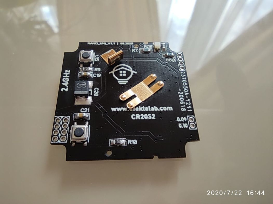
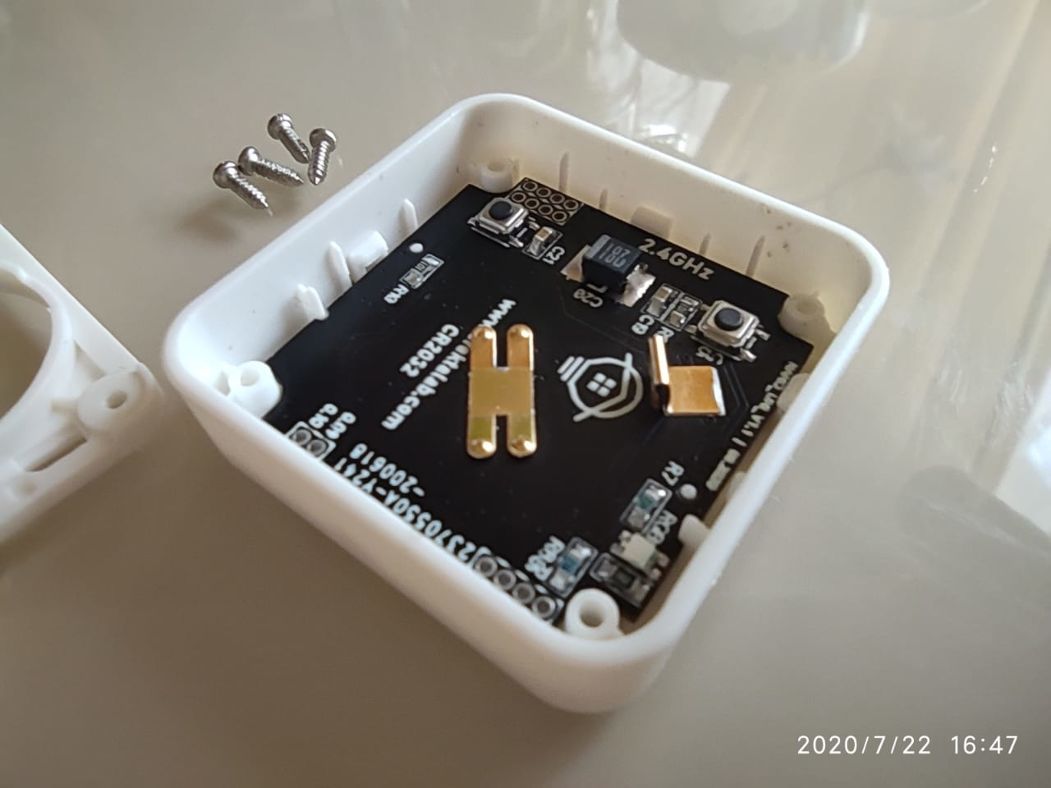
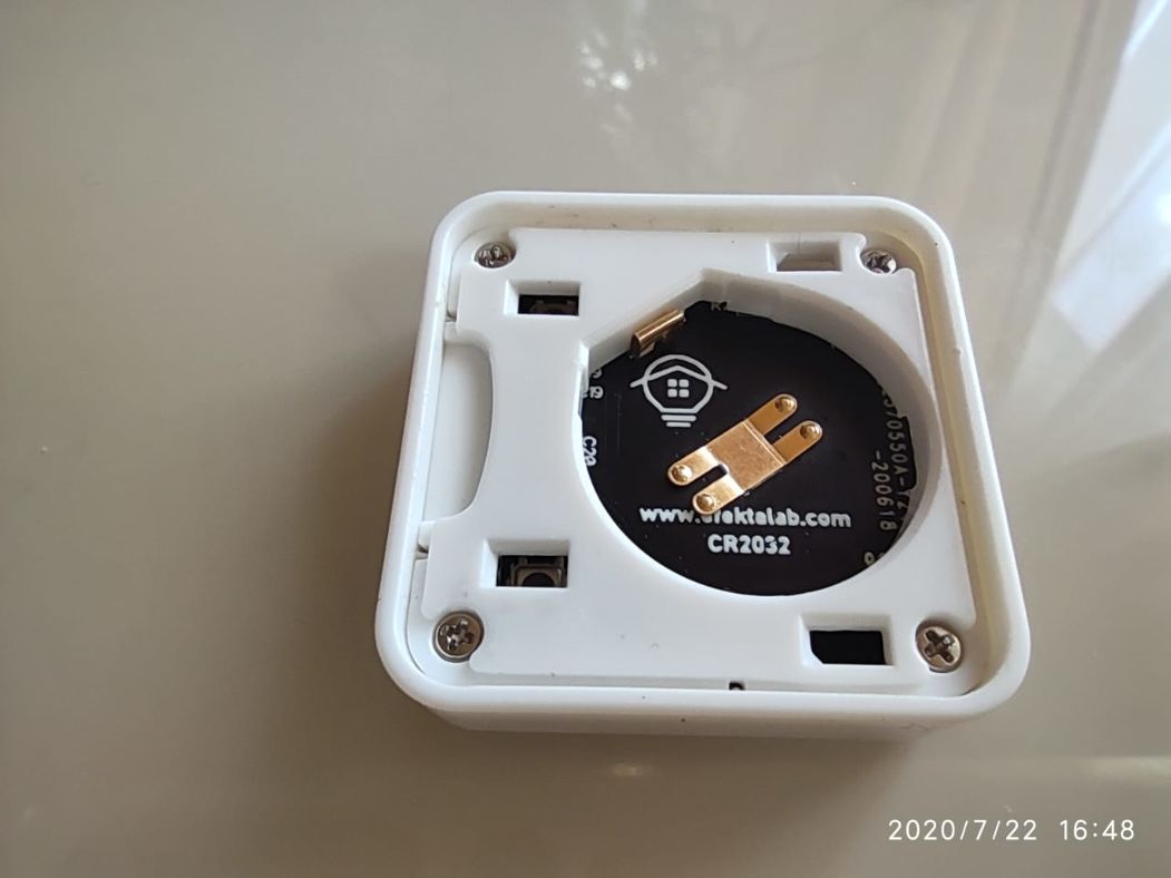
Now I have 4 such devices at home, two of them are temperature and humidity sensors with Si7021 sensors (one on nRF52832, the second on nRF52811), one is a shock sensor implemented on the LIS2DW12 accelerometer (nRF52810) and a temperature control sensor on the LMT01 sensor (nRF52810 ).
The wireless sensor is powered by a cr2032 battery, consumption in sleep is 1.8μA for nRF52810, nRF52811 and 3.7μA for nRF52832. Consumption in data transmission mode 8mA.
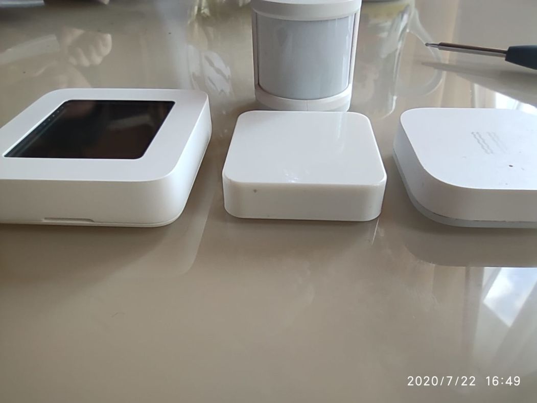
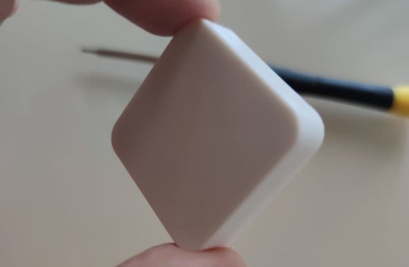
The description of the protocol used, the development of software for this sensor for different scenarios of use, I think, is beyond the scope of this article.
The test of the sensor's operation with the smart home system can be viewed in a short video below.
The project of this sensor is open source, you can get all materials on the project on my GitHub .
If you are interested in everything related to DIY, you are a DIY developer or just want to start, you are interested in using DIY devices, I invite everyone interested in telegram chat - DIYDEV .
For everyone who wants to make devices, start building automation of their home, I suggest that they familiarize themselves with the easy-to-learn Mysensors protocol - telegram chat MySensors.And
for those who are looking for mature enough solutions for home automation, I invite you to the Open Thread telegram chat . ( what is Thread? )
Thank you for your attention, all the best!

