Why is it needed
The idea to assemble a homemade tablet computer came to my mind a few years ago. At the end of the 2000s, the so-called UMPCs were popular - devices based on x86 architecture processors, capable of running all the usual programs for desktop computers (well, not all, but those that the power of the "hardware" will allow) but at the same time fit if not in a pants pocket. then at least in the pocket of your winter jacket. Often such devices, in addition to a touchscreen, had a QWERTY keyboard, moreover, in a form factor optimized for work "on the weight", as well as a touchpad or trackball for precise positioning of the mouse cursor (which was especially important given the low accuracy of touch screens of that time and the interface " desktop programs, not designed for small screens and touch input). At that time, many thought that the future belonged to such devices.They were supposed to become real helpers in work, allowing you to work not only in the office and at home, but in general anywhere, and it is not even necessary that at the same time there would be a horizontal surface on which to place your gadget. I myself was the proud owner of one of these devices. My UMPC was a horizontal slider form factor with a QWERTY keyboard, touchpad and 7-inch touchscreen. And this device really helped save time. With his help, a significant part of my thesis was done - and not only an explanatory note was written, but also the program code was written, compiled and debugged. I did all this right in the subway on the way to college, to work, and then home,and for this it was not even necessary to look for a seating place - the size and form factor of the device made it possible to work quietly while standing. Travel hours were no longer wasted, and when I returned home, I could afford to spend the evening on other activities.
However, there are no eternal devices, electronic equipment is rapidly becoming obsolete. My UMPC initially had very weak hardware, even by the standards of its time, and after a few years it was no longer possible to use it even for the simplest tasks. I tried for a long time to find a replacement for him, but such devices went out of fashion, and they ceased to be produced. Then (several years later) I decided to assemble such a device myself. As a result, the assembly process took a very long time, I was engaged in it in fits and starts, at the same time pumping the skill of working with a soldering iron. Now many things had to be abandoned, and the appearance of the device still leaves much to be desired. But oddly enough, despite the absolutely amateurish approach to design, in general, the device turned out to be efficient.
What's important about a homemade laptop
There are many descriptions of various homemade laptop computers on the Internet. Industrial motherboards of various compact form factors are often used as a base for them. These motherboards usually contain a CPU with low or ultra-low power consumption, memory slot (s) "laptop" SO-DIMM form factor or pre-wired memory, and an LVDS connector that allows you to connect a laptop screen. I went the same way. But the main problem that I could not solve for a long time was how to make the assembled computer "consider itself portable", that is, at the operating system level, it "knew" about the presence of a battery, would display its current state and the forecast of the remaining screen time,supported various power consumption modes (including the maximum power saving mode) and switching these modes in a couple of clicks, and not in a complex sequence of actions, and in case of a critical decrease in the battery level, it would automatically go into hibernation mode before the voltage drops so much that work will be interrupted "Emergency" order. In all the descriptions of self-made wearable devices that I could find, this problem was either bypassed, or an operating system with the most open source code and great opportunities was used for developing device drivers, modifying key system modules or creating new ones (often based on Arduino). I needed to provide support for traditional "desktop" operating systems, including Windows. Oddly enough, there is no pertinent information abouthow to do Windows compatible battery management, I haven't found. This is still surprising to me, perhaps I was just looking in the wrong place, but nevertheless, the idea described below came to my mind on my own, and therefore I am talking about it here.
So, I realized that I need some kind of battery controller that supports the ACPI standard. And I knew that there are some non-intermittent power supplies that support this standard. In computers to which such a UPS is connected (via a USB port), the standard Windows battery icon appears on the taskbar, and all the functions described above also appear with it. I was already thinking about buying a similar UPS, picking out the control board from it and trying to reflash it for the new battery characteristics, but I found an easier way - to use a device called OpenUPS. This device is a universal battery controller board that is easily customizable for a variety of needs. It supports different types of batteries (both lead and lithium polymer) and a different number of battery cells.There is also a function of balancing the cells when charging, and it is very easy to set all the required parameters using a special program with a graphical interface. This was what I needed.
Component set
Thus, the general concept of the device was formed. It must contain the following mandatory components:
- PicoITX motherboard;
- OpenUPS battery controller;
- lithium polymer battery of 4 cells, connected in series (to provide a supply voltage of at least 12 volts, even with a minimum charge);
- a screen with an LVDS connector, built into it or a separate touch panel with a controller supporting multitouch mode.
In addition, additional components are possible - as far as the size of the device and the battery capacity will be. It is highly desirable to have a built-in GSM-module, and if possible with voice functions, so that the device can be used as a smartphone. And I would also like to equip the device with a physical QWERTY keyboard, either located under the screen (sliding in the form of a horizontal slider) or consisting of two halves on both sides of the screen. After all, this should be a device for work, and not just to watch photos in social networks?
Moreover:
- the processor must be x86-64 architecture, "notebook" series with reduced power consumption, but at the same time the most powerful available;
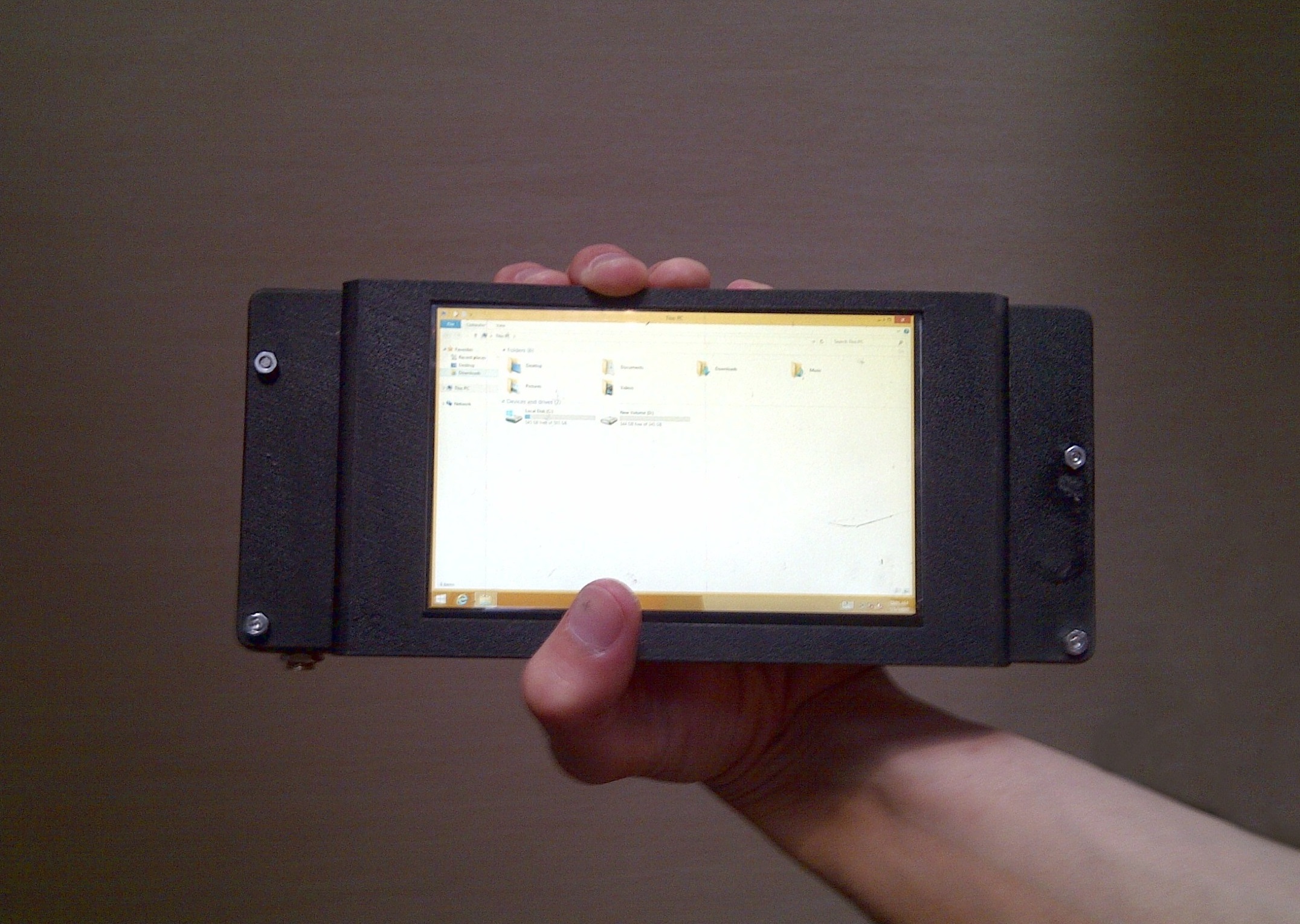
- the device should fit normally in the palm of your hand if you take it by the narrow side of the screen (i.e., as shown in the title photo), and at least somehow fit into at least the largest pocket of all my jackets - both winter and summer. Winter jackets are easier - they usually have large pockets. Summer is more difficult.
This is roughly what I wanted to get:

Well, the boundary conditions are defined, some details have already been selected. Go to work!
Build process
After looking through various PicoITX motherboards, I found the Axiomtek PICO512 model. It was powered by an Intel Core i7-7600U processor, and at least at the time, it was the most powerful option I could find. One SO-DIMM form factor RAM module with a capacity of up to 16 GB could be installed on the board. I wanted to build the most powerful device, and immediately bought 16 gigabytes of RAM, as well as a terabyte mSATA SSD.
Immediately there was a problem with cooling. As usual, the board was cooled by a huge aluminum radiator, the dimensions of which made it possible to consider the board as satisfying the PicoITX standard only formally: the dimensions of the radiator significantly exceeded the dimensions of the board itself. For obvious reasons, this option did not suit me. Therefore, I decided to use a very small copper heatsink installed on the processor, and on the other side, this heatsink should be attached through thermal paste to the general frame of the device, made of aluminum. At the same time, the frame should become such an additional ersatz radiator. A small laptop fan should be located on the side of the copper radiator. Unfortunately, I did not succeed in the liquid-cooled notebook type. The thermotube simply had nowhere to go - the device must be very small,and the only free space was right above the processor. I was afraid that the new cooling system would not cope at all. But it turned out that everything is not so scary, although far from ideal. In "office" mode, the cooling system copes with the heat dissipation of the processor. At full load, it lasts for about a couple of minutes - then overheating and throttling begins. This is not suitable for games, but in the everyday work of a programmer (we write the code for a long time, while the processor is mostly idle, then we compile this code as quickly as possible) such a cooling system manifests itself normally. And in some distant plans - to try to use the evaporation chamber. Perhaps it will help bring the heat sink to the ideal.that everything is not so scary, although far from ideal. In "office" mode, the cooling system copes with the heat dissipation of the processor. At full load, it lasts for about a couple of minutes - then overheating and throttling begins. This is not suitable for games, but in the everyday work of a programmer (we write the code for a long time, while the processor is mostly idle, then we compile this code as quickly as possible) such a cooling system manifests itself normally. And in some distant plans - to try to use the evaporation chamber. Perhaps it will help bring the heat sink to the ideal.that everything is not so scary, although far from ideal. In "office" mode, the cooling system copes with the heat dissipation of the processor. At full load, it lasts for about a couple of minutes - then overheating and throttling begins. This is not suitable for games, but in the daily work of a programmer (we write the code for a long time, while the processor is mostly idle, then we compile this code as quickly as possible) such a cooling system manifests itself normally. And in some distant plans - to try to use the evaporation chamber. Perhaps it will help bring the heat sink to the ideal.but in the daily work of a programmer (we write the code for a long time, while the processor is mostly idle, then we compile this code as quickly as possible) such a cooling system manifests itself normally. And in some distant plans - to try to use the evaporation chamber. Perhaps it will help bring the heat sink to the ideal.but in the everyday work of a programmer (we write code for a long time, while the processor is mostly idle, then we compile this code as quickly as possible) such a cooling system manifests itself normally. And in some distant plans - to try to use the evaporation chamber. Perhaps it will help bring the heat sink to the ideal.
As for the fan, there was an additional problem with it. There were only two wires from the motherboard to the fan. No fan control programs at all saw its presence in the system. This means that its speed is not regulated in any way and, it always rotates at the same maximum speed, even when it is not required. In terms of battery drain and device noise, this was no good. But I figured I would just plug the fan through a transistor driven by a thermistor and that should fix the problem.
I chose the screen with a diagonal of 5.6 inches. I found a model with an LVDS connector and a resolution of 1280 x 800 pixels. By modern standards, this resolution is quite small, but for such a small screen it seems to me sufficient (especially for a "desktop" operating system that is not designed for small screens). Taking into account the dimensions of the screen, the motherboard (10 x 7 cm) and the battery controller board (in fact, it turned out to be too large for my purposes, as much as 10 x 5 cm, and with huge capacitors sticking up), the overall dimensions of the device were roughly determined. The length will be a little more than 21 cm, the width - 9 cm. As for the thickness ... Yes, everything is bad here. Not less than 3 cm, but rather closer to 4. Compared to modern smartphones, about which someone has already said that they can cut cheese, this is just a disaster.But by the UMPC standards of the turn of zero-tenths, these are normal sizes. And in the palm of a similar device should lie quite comfortably.
This is how the aluminum frame looks like, to which all other components of the device are attached. I folded the frame from the usual corners bought in a building materials store. This allowed me to assemble a working prototype, but later I will try to order the production of a new frame in some factory way.

Two plastic covers are attached to the frame at the top and bottom. The top one is the screen frame, the bottom one is the battery compartment. I ordered the plastic parts from a 3D printing company. The screen contained a touch panel, but it was resistive, so I had to look for a separate capacitive panel. There was practically no choice of ready-made panels of the required size, and the only more or less suitable specimen found was slightly wider than the screen. The panel was able to be calibrated to the actual size of the visible area of the screen, but its edges stick out strongly to the sides, taking up valuable surface where something else could be placed.
The battery is easily removable. Its 4 cells are inserted into a separate plastic case with flat contacts on one side. Mating contacts for them are fixed on the frame. There is a latch on the back of the tablet that allows you to easily detach the battery from the device.

Each battery cell is a regular 3500 mAh lithium polymer battery. According to calculations, this should have been enough for about 5 hours of device operation in "office" mode. But unfortunately, the actual battery capacity turned out to be two times lower than the declared one. And there was also a "bug" of the controller - it does not know how to properly consider the possibility of reducing the battery capacity. How many were set in the settings - we count on so much. As the battery discharges, the OpenUPS driver, as I understand it, calculates the current charge from the consumed energy (i.e., integrating the power and subtracting the resulting value from the original hard-coded value of the full capacity) ... and then suddenly it turns out that the battery is completely gone to zero. Inconvenient. I don't know what to do about it yet.
Current result
Unfortunately, further the process of creation was delayed for several years. There was not enough free time, a huge number of technological problems arose. Most of these problems came down to how to fit a huge number of components into a very compact case. I originally wanted to design and manufacture in one way or another some common "peripheral board" on which all additional components will be soldered. But so far I do not have enough time for this. Therefore, to create a prototype, it was necessary, in the best traditions of novice home-builders, to simply cram all possible ready-made boards into the case that could fit there. As some excuse, I can say that my old UMPC was, although factory assembled, it also consisted of a large number of small scarves.
Here is a complete view of the device from the outside as it stands today. A single USB port is visible from the side (I hope there will be more of them later, but this will require an additional hub), as well as a standard 3.5 mm combined audio input / output. Also on the same edge there is a button to turn on the device. Ventilation slots are visible along the edges under the top cover.
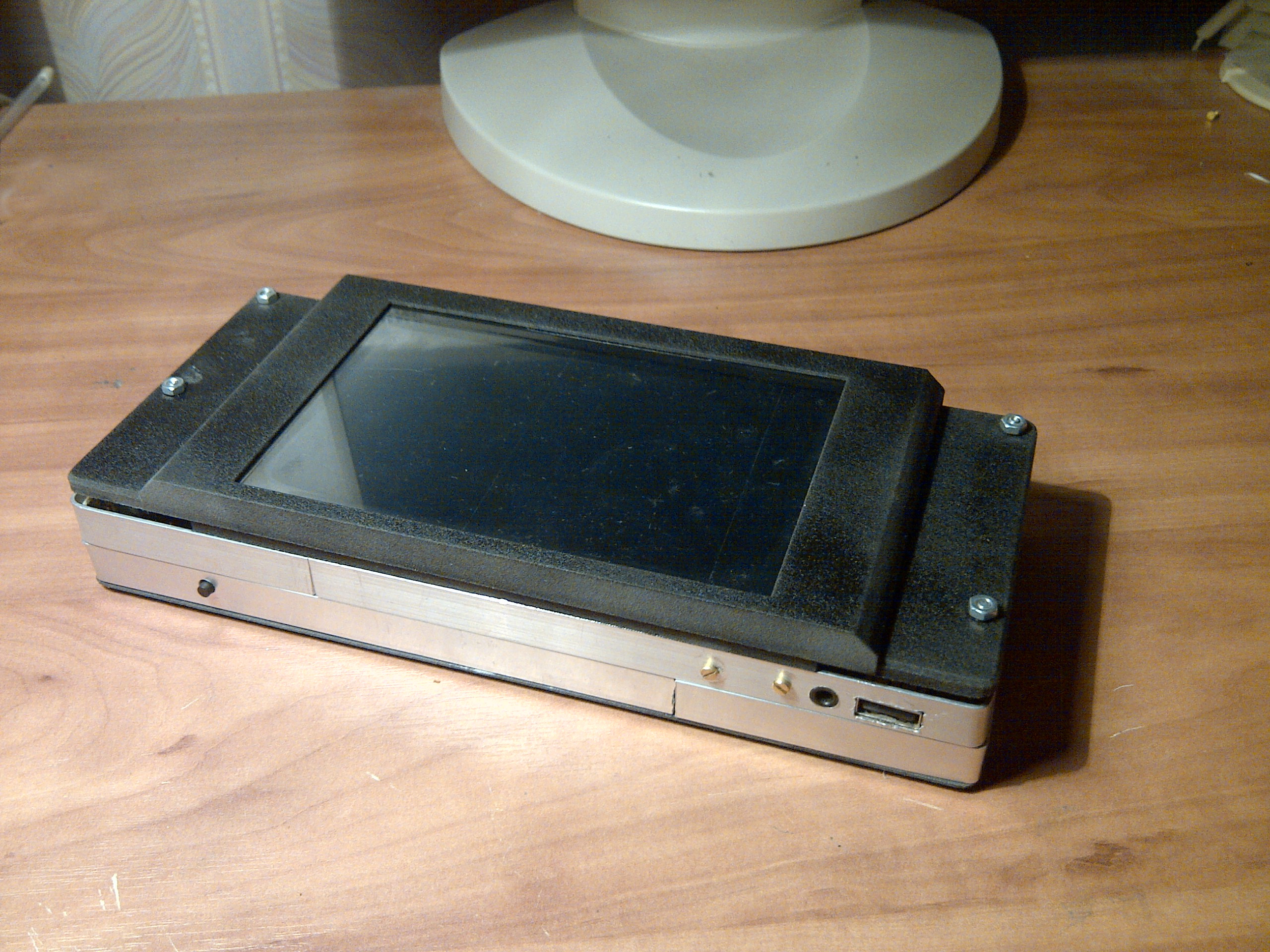
The opposite edge is best seen in the photo of the frame without the top cover shown above. The HDMI connector is located on this edge. Next to it on the motherboard is the LAN connector, which I do not need, and even frankly interferes - without it, it would be possible to make the design a few millimeters thinner. I did not make a hole in the case for it. And the power connector that sticks out next to HDMI is also absolutely unnecessary and even harmful in the current configuration. Power is now supplied through the battery controller board and further along the wires that are soldered to the holes on the motherboard next to its standard connector. The standard connector must be completely evaporated, and this is in my immediate plans.
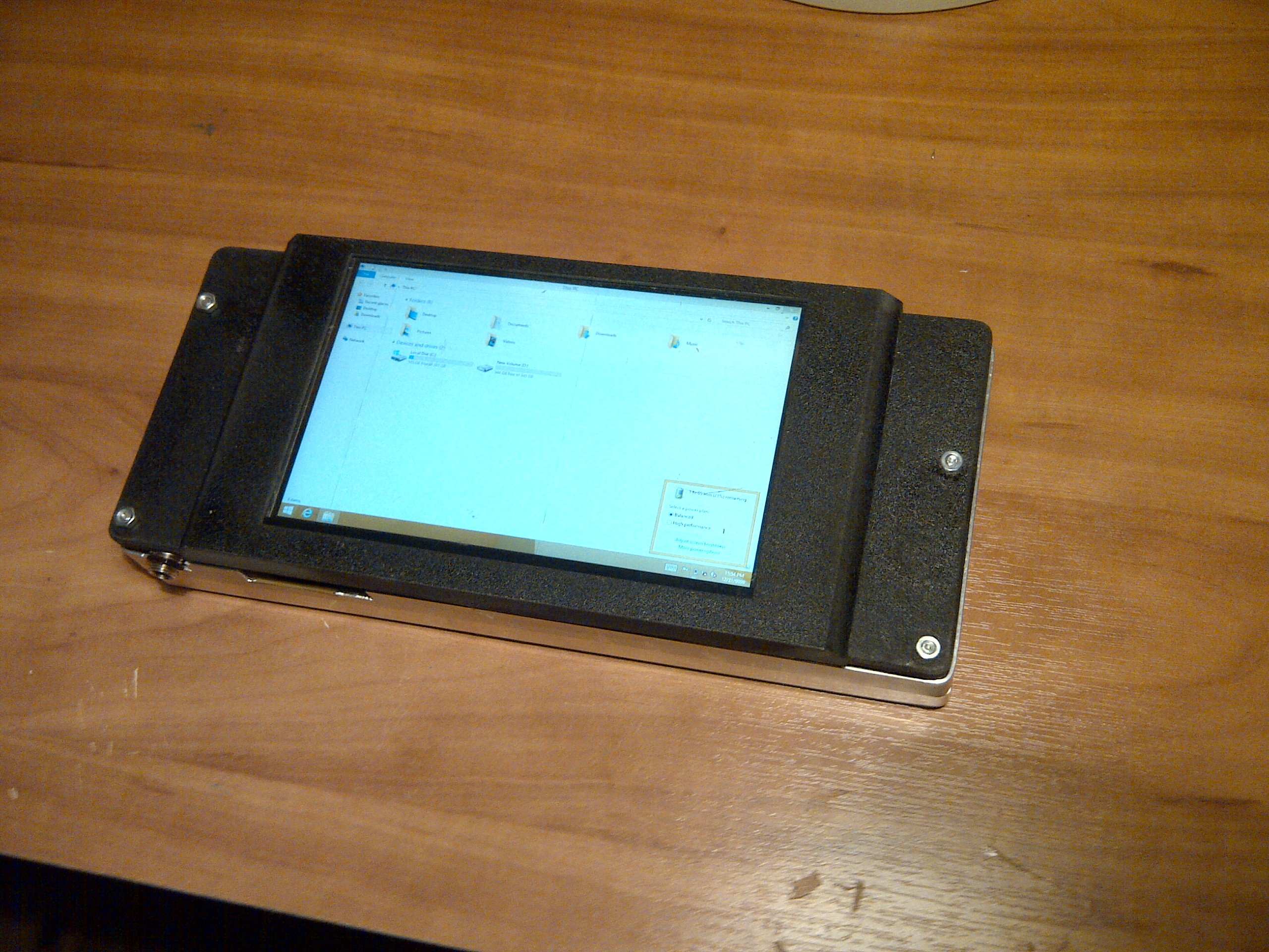
This is how the device looks when turned on:
The hardware keyboard has yet to be made, but I hope to still implement this important element in the foreseeable future. Then the device can be used for its original purpose. I hope that the keyboard can be placed over the edge of the motherboard in the thinnest part, and the device will take the form factor of a horizontal slider, as I intended to do originally. There have already been articles about creating homemade keyboards on Habré, so I hope that I can also make my keyboard in the same way.
And I have already tried to install a GSM module with support for voice calls (again, in the form of a separate ready-made board). It worked, it could be used, but in the current configuration it did not fit into the case a bit and was sticking out about literally a few millimeters. So far I've removed it. If I can move all the components a little, it should fit in, and I will have my own personal smartphone based on Core i7.
Main conclusions
The device, of course, is still quite "raw" now. I managed to bring it to a more or less workable state, but further development could take years more if I do not abandon it at all. Then what is the most important result of this project that I can share here? I believe that this is the very concept of the scheme "industrial motherboard + OpenUPS controller or similar". Such a scheme allows you to assemble a fully functional laptop computer for any needs, even for a person who is very poorly versed in electronics. And if, when creating my particular device, I had to constantly struggle with the lack of space for components and make compromises, then a tablet or laptop of normal size on a similar platform will be free of these problems. They will easily fit any required peripherals. I remembersome time ago, some of the Khabrovites already dreamed of a "normal laptop for work", complaining, like me, about the dominance of devices suitable only for viewing social networks. With a strong desire, he will be able to make himself a "dream laptop" on his own, according to the same principle as my device. And such computers will be easy to upgrade - of course, it will be possible to replace the RAM and long-term storage, but if you wish, you can even change the motherboard if the new motherboard has the same form factor as the old one.And such computers will be easy to upgrade - of course, it will be possible to replace the RAM and long-term storage, but if you wish, you can even change the motherboard if the new motherboard has the same form factor as the old one.And such computers will be easy to upgrade - of course, it will be possible to replace the RAM and long-term storage, but if you wish, you can even change the motherboard if the new motherboard has the same form factor as the old one.
Finally, I would like to dream that someday someone will organize a startup to develop a universal "industrial motherboard to laptop converter" - a motherboard that will have an ACPI-compatible battery controller similar to OpenUPS and some standard laptop peripherals. First of all, there must be wireless interfaces, perhaps also a touch panel controller (if it is universal enough to connect panels from different manufacturers and different standards). The creation of such a device would allow ordinary DIY enthusiasts to develop their own laptops and tablets. They could dilute a huge number of existing devices of the same type, similar to each other like two drops of water.
Who will undertake such a project?