Mitsubishi VisiTel
When this device appeared in 1988, it definitely represented the future. And with its low price - only $ 399 - how could it not immediately become popular? In the magazine Popular Mechanics, published in February 1988, a whole page was devoted to Mitsubishi VisiTel. The device was described there, mentioning an unexpectedly large amount of technical details. And the presenters of Gadget Guru on the WSMV TV channel, immediately after they started talking about VisiTel, asked an incredibly important question: "Can I continue to use a regular phone while this thing is connected to the line?"
It took 30 years and a global pandemic for us to finally accept the inevitable fact that before calling colleagues we need to take a shower and put ourselves in order. Now, whatever one may say, there is no escape from video telephony.
I'm not the first to think there is something particularly kitschy about VisiTel. People have been tinkering with this device for a long time. Despite the fact that it does not transmit a video signal, but only allows you to share photos, it is one of those products that are considered to be outstanding achievements in engineering. This is a development that was well ahead of its time.
My interest in VisiTel appeared after thisvideo. Its author showed how, by slowing down or speeding up the capture of an image sent by VisiTel, you can make the image on the screen distort. Upon learning this, I immediately realized that the device uses a simple amplitude modulation scheme. Knowing this, I went to eBay and found a suitable copy of VisiTel there. My goal was to make this amazing "time capsule" with the technical advances of the late 1980s work in conjunction with the modern technologies I have chosen. In particular, I wanted to organize communication with colleagues at Zoom. Moreover, I wanted to achieve this without having to modify the VisiTel hardware. There is something special in this device, such that you want to leave it in its original form.
Step 1. Connection

Start experimenting with VisiTel
VisiTel is ridiculously easy to get up and running. From the back of the device comes a long cable with a Y-shaped splitter towards the end (more on this below) and a pair of connectors. One of them is a 2.1 mm power connector. The device needs 15 volts. It is somewhat strange that the developers of the device decided to write the number 15 in such a font that the inscription reads "IS Volts". The second connector is a regular RJ-11, which uses two pins. This is a standard phone jack. If you remember ordinary wired telephones, then you can also remember that the handset is connected to the device using the RJ-9 connector, and the phone is connected to the line using the RJ-11 connector. The meaning of this is that it would be possible to connect not only a handset to the phone, but also something else, as well as the fact thatso that you can replace the cable or tube in the event that something happens to them. True, it cannot be said that something often happened to the cables going from telephones to handsets, since special, very flexible wires were used in their manufacture.

VisiTel
, VisiTel
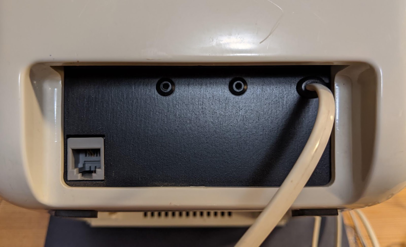
If we go back to the back of VisiTel, there is, in addition to the cable, an RJ-11 connector. After I thought for some time about why he was needed there, it dawned on me. The device acts as an intermediary between a regular telephone set and a telephone line. This allows VisiTel to monitor the line or transmit images during regular phone calls. This leads to an obvious problem. Namely, we are talking about the fact that since VisiTel uses the telephone line simultaneously with the telephone, the subscriber will hear the sounds accompanying the receipt and sending of images. But Mitsubishi engineers took care of that. Before sending or receiving an image, you can hear a loud click, indicating that some relay turns off the phone for a while. We are going to use VisiTel so that the audio signal received from the device is not interesting to us,therefore we will not connect anything to the RJ-11 connector on the back of the device. This makes the corresponding relay unnecessary, which means it can be removed in order to get rid of the clicks associated with sending the image.
How to organize data exchange with this device? For example, my computer does not have an RJ-11 connector. True, this is not scary, since there are adapters on sale for connecting handsets with RJ-9 connectors to smartphones. One of the connection options is that you can cut off the RJ-11 connector and solder a 3.5mm plug to the wire, organizing mono audio transmission. Note that I originally assumed VisiTel had an RJ-9 connector and not an RJ-11 connector.
Using the 3.5mm plug, connecting VisiTel to your computer is extremely easy. Namely, you need to get a USB adapter with separate outputs for connecting a microphone and a headphone (not TRSS) and connect VisiTel to a suitable connector.
Above, I said that I will return to the Y-shaped splitter. My VisiTel had some kind of problem with the wires around this splitter. Moreover, the wire was not broken when everything simply refuses to work, and when the problem is completely obvious. It was one of those unpleasant malfunctions where everything works in the evening and no longer the next morning. It would be nice if the creators of VisiTel used special flexible wires in their product. This problem, which appeared and disappeared, cost me many days in a senseless search for its solution. I searched for overheating problems without much successdevices, checked the audio card settings three times. I ended up finding the problem when I lifted the device up during testing. After that, I found characteristic signs of a broken connection in the recording. One lesson I learned from this story is about working with old hardware. It consists in the fact that, during the operation of the device, you need to move it a little and see if everything at this time functions the same as before.
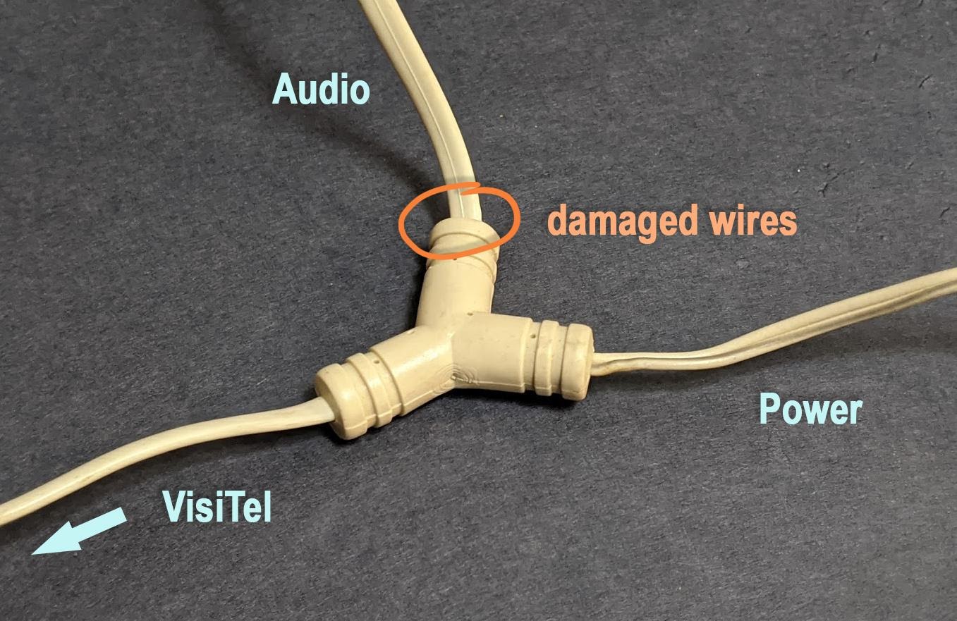
The place of wire damage is marked with a circle
Step 2. Exploring the image transmission mechanism
After we solved the problem with the tricky wires and connected the device to the computer, it's time to figure out which protocol is used to encode the transmitted images. Videos and articles about VisiTel allow us to conclude that images are encoded using amplitude modulation of the audio signal. Amplitude modulation is data coding performed by changing the amplitude of a carrier signal. Amplitude modulation is commonly used to encode sound transmitted using radio waves, but the same approach can be used to transmit images using radio waves or even sound waves. Hereyou can find an excellent detailed description of this process with examples of Python code, intended for those who are used to learning new things through practice.
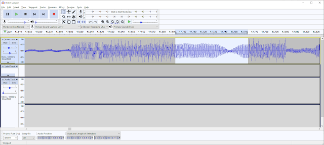
Knowing that the data is encoded using the AM modulation mechanism of the audio signal, we can take the first step towards decoding this data. This step consists in recording a modulated signal that transmits a sample image with previously known properties. To capture the audio signal, I used Audacity , my usual audio software.
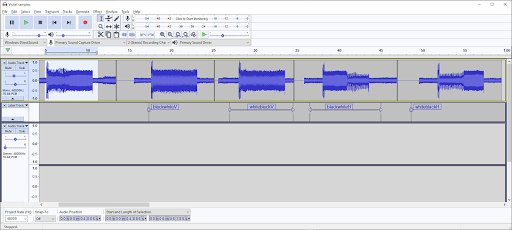
Graphical representation of the audio signal The
above shows how I, in an effort to better understand how the data is encoded, sent a very simple, specially prepared image from VisiTel. This image, shown below, was a pair of cards, black and white, which I held in front of the device's camera. The signal corresponding to it is marked in the program as
blackWhiteV.

Image used in the experiment
Let's take a closer look at the received audio signal.

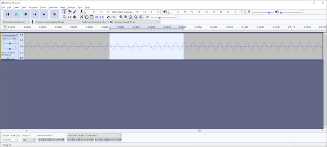
Taking a closer look at the audio signal
You can listen to this signal here .
As you can see, at the beginning of each block there is a header, or sequence, indicating initialization (from 17.55 to 17.80 in this example). This allows the receiving device to know that another device is about to transmit an image and to determine the maximum signal amplitude. This indicator is then used as a scaling factor when decoding the image. As a result, telephone line imperfections will not result in image loss of contrast or brightness. The signal transmitted on some lines may be noisy or weakened. Note that the signal up to 17.55 is just noise, not important to the data protocol used by VisiTel.
To make sure that the header sequence I found did indeed indicate to VisiTel that another device was about to send it an image, I let the device listen to just this small piece of the recording and was rewarded with a relay click. It was obvious that this sequence sets in motion some mechanisms. But after sending the device only 30 milliseconds of the header, I realized that the device detects that the image after the header is not transmitted. The relay turns off a few milliseconds after the end of the header transmission. If you play the title and the first few milliseconds of the sound following it, then VisiTel starts displaying the image on the screen. If you turn off the sound while the device is displaying an image on the screen, then the work continues,VisiTel continues to receive some data until the buffer used to store the image is full. This proves once again that after VisiTel starts processing graphic data, the device does not rely on an external oscillator to find out exactly where the data it needs is encoded in the signal. He has his own clock generator that tells him exactly where what he needs.where exactly is what he needs.where exactly is what he needs.
Since the header part of the signal is only responsible for establishing the connection, and given the fact that it does not depend on the transmitted image, I had no desire to delve into the study of its features. To achieve our goals, it is enough for us to know that the header is responsible for establishing a connection, and also it is enough to have a rough idea of how it looks.
And now it's time to move on to the most difficult part - to find out exactly how the graphic information is encoded, how the pixels "sound". First, I needed to understand how the pixel data is represented in the audio signal. My first guess was that each full wave represents one pixel. I tested this idea by counting the number of waves between repeats of the test pattern. What I got was in line with the VisiTel specifications from the old ad. Namely, it is 96x96 pixels, with several lines being output before the start of the image itself.
All this means that the device analyzes the amplitude of each wave and writes the data in the form of a buffer pixel, which represents a digital image in VisiTel. We know from VisiTel marketing materials that every pixel in the image it displays has 16 shades of gray. But I, analyzing pixels from the "analog" signal, did not feel the need to apply the effect of posterizing them when decoding or encoding.
Interestingly, the brightness of the pixels is inverted before modulation. As a result, the largest waves correspond to the darkest pixels. In addition, the image is reflected from left to right, that is, a mirror image is formed. I would like to know what the readers of this material think about the reason for inverting the brightness of pixels before transmitting the signal. I suspect that this is because human vision is calmer about randomly scattered black pixels than similarly white ones. After all, noise on telephone lines is a problem that VisiTel definitely had to contend with in 1988.
Signal investigation
True, there was one exception to the above image encoding scheme that eluded me for several weeks. With this inverted coding scheme, perfectly white pixels should be represented by silence. There should be no signal representing such pixels. But I got the feeling that the creators of VisiTel didn't like this idea. Instead, to encode all-white pixels, the carrier signal was shifted by 1/4 wavelength, resulting in such waves out of phase with the normal ones. In this case, the signal could be sent to another device, as before. The receiving device, receiving such a signal, kept synchronization with the "normal" signal and took information about the signal amplitude in the same place as usual, but now at these moments the wave passed through 0,which gave the pixels white. As I already said, if you turn off the sound during the transfer of the image, then VisiTel continues to display the image until the buffer is full. These are white pixels. As a result, it turns out that silence, even without the presence of a useful signal in the line, is perceived by the device as white. I don't know why the creators of the device decided to complicate the modulation scheme by introducing such a phase shift mode into it. As for me, a lot of effort was spent on this, but there is either no benefit from such a step, or it is very insignificant.for which the creators of the device decided to complicate the modulation scheme by introducing such a phase shift mode into it. As for me, a lot of effort was spent on this, but there is either no benefit from such a step, or it is very insignificant.for which the creators of the device decided to complicate the modulation scheme by introducing such a phase shift mode into it. As for me, a lot of effort was spent on this, but there is either no benefit from such a step, or it is very insignificant.
I, not knowing about phase shift modulation, initially tried to find the maximum of each of the waves and represent the resulting value as a pixel. Line breaks were performed with a step calculated by the formula
96*( ). This led to the fact that in some lines there were either a little more or a little less pixels. In addition, such a crude approach to signal analysis was very sensitive to noise, since even small peaks in the waves could lead to the appearance of extra pixels. True, such an image decoding mechanism was very simple to implement. Implementing this simple idea could decode images without the need to synchronize the receiver and source. But after applying such a signal decoding system, nothing decent happened to me.
In order to decode images more accurately, we need to do the same as VisiTel does. Namely, you need to synchronize with the signal at the time of header processing, and then sample the signal at regular intervals. Not surprisingly, such signal processing requires very precise timing. In my case, when recording sound with a frequency of 44100 Hz, there are 25.23158 samples per wave (this means that the frequency of the carrier wave is 1747.80968929 Hz). As a result, every time we read information about a pixel, we will look in the audio buffer for data on the next pixel at a distance of 25.23158 samples from the previous one. Since sample positions are described by integer values, we simply round the corresponding number to the nearest integer and use it. The most important thing here is to prevent rounding errors from accumulating,as this will cause the sampling position to quickly move out of phase with respect to the sound wave. And if a similar displacement occurs during image decoding, albeit a small one, the finished image will be filled with artifacts.
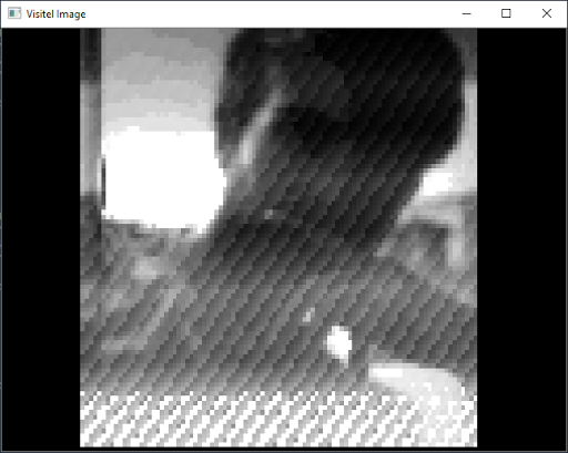
Image full of artifacts
Luckily for me, the number of samples per wave is quite stable. It did not change after the device warmed up, although I was worried that this could be a problem. This stability allowed me to simply hard-code the appropriate value in the image decoding code. Ideally, the number of samples per wave should be learned from the title, but I found that there were not enough samples to achieve an accuracy of 5 decimal places. And the value, hard-coded, made it possible to achieve stable results. Thanks to this more accurate implementation of the signal decoding system, line breaks were simply performed after the function that generates 1 pixel was called 96 times.
So far I have worked with pre-recorded audio snippets decoded from WAV files. In order to work interactively and decode images entering the audio interface of the computer, the decoder had to be equipped with the ability to detect the header and find the beginning of the image data. If you look at the headline, it turns out that there are three clearly distinguishable fragments in it.
Header Analysis: Carrier - Silence - Carrier
In order to detect this, I implemented a simple FFT- based detectorand state machine. The original material is processed first, and then the detector examines each block of the audio signal until it finds a strong 1747 Hz signal. The blocks are then examined until they find the place where the signal disappears and then reappears. This means finding the moment to start transmission. Thereafter, a simple static offset is used to find the start time of the image data transmission, and the above mechanisms are used to decode the image. After decoding is complete, the image is displayed and the state machine is reset to its original state and waits for the next transmission to begin.
Step 3. Presenting VisiTel as a webcam
Now that we have been able to decode the image received from VisiTel, it remains to put the last piece of our puzzle in place. We need to present the decoded images in the form of video frames and transmit the video stream to the video conferencing program. This is surprisingly easy on Linux. The video input is abstracted using the V4L2 interface, but this unfortunately happens in kernel space. In order not to get involved in the complexities of creating a kernel module, you can use a ready-made solution - v4l2loopback... This module is both an input device and an output device. The graphics input that is passed to it becomes output that other programs like Zoom can accept. There are even Python packages that abstract this even further, allowing you to work with this kind of data using OpenCV and NumPy. I used one of these packages -
pyfakewebcam. It features an extremely simple interface. To create a virtual webcam, just do the following:
import
      pyfakewebcam
self.camera
    =
    pyfakewebcam.FakeWebcam(self.v4l2_device, 640, 480)
And when you receive a new frame, you need to do this:
self.camera.schedule_frame(output)
Now, after this little addition to the decoder, everything worked as it should. Zoom can receive images from VisiTel, and we can organize video chat in the style of the 1980s.

Video chat in the spirit of the 1980s
I would also like to install the Linux driver Direct Rendering Manager, which will allow not only receiving images from VisiTel, but also displaying them on it. But for now, in order to recognize this project as a success, it is enough for me that I can communicate in Zoom using a device from 1988. Here , if you're interested, is the project code on GitHub.
Have you tried to give a second life to some devices from the distant past?