
... As you read the attack described in this article, keep in mind that it applies to revision 0 and 1 ESP32 chips. Newer ESP32 V3s support the UART bootloader disable functionality used in this attack.
UART bootloader
In ESP32, the UART bootloader is implemented in ROM code. This makes it possible, among other things, to write programs to external flash memory. Implementing the UART bootloader as code stored in ROM is a common solution. It is quite reliable due to the fact that such code is not easily damaged. If this functionality were based on the code stored in external flash memory, then any damage to such memory would lead to the complete inoperability of the microcontroller.
Usually, access to such functionality is organized when the chip is loaded in a special mode, in boot mode. The choice of this mode is carried out using contact jumpers (or jumpers) installed before the device is rebooted. The ESP32 uses pin for this
G0.
UART bootloader supports many interestinginstructions that can be used to read / write memory and registers and even execute programs from SRAM.
▍Arbitrary code execution
UART loader supports loading and executing arbitrary code using command
load_ram. The ESP32 SDK includes all the tools needed to compile code that can be executed from SRAM. For example, the following code snippet outputs a string SRAM CODE\nto the serial interface.
void __attribute__((noreturn)) call_start_cpu0()
{
    ets_printf("SRAM CODE\n");
    while (1);
}
The tool
esptool.py, which is part of the ESP32 SDK, can be used to load compiled binaries into SRAM. Then these files can be run.
esptool.py --chip esp32 --no-stub --port COM3 load_ram code.bin
Interestingly, the UART bootloader cannot be disabled. Therefore, there is always access to it, even if secure boot and encryption of flash memory are enabled.
▍Additional security measures
Obviously, unless additional security measures are taken, the constant availability of the UART bootloader will make the secure boot and encryption mechanisms of flash memory practically useless. Therefore, Espressif has implemented additional security mechanisms that are based on eFuse technology.
These are the bits used to configure the security parameters, which are stored in a special memory often referred to as OTP memory (One-Time-Programmable Memory). Bits in such memory can only change from 0 to 1, but not in the opposite direction. This ensures that if a bit enabling a feature has been set, it will never be cleared again. When the ESP32 is operating in the UART bootloader mode, the following bits of the OTP memory are used to disable certain capabilities:
DISABLE_DL_ENCRYPT: -.DISABLE_DL_DECRYPT: -.DISABLE_DL_CACHE: MMU- -.
We are most interested in the OTP memory bit
DISABLE_DL_DECRYPT, as it disables transparent decryption of data stored in flash memory.
If this bit is not set, then, when loading the microcontroller using the UART bootloader, you can organize simple access to the data stored in the flash memory, working with them as with ordinary text.
If this bit is set, then, in boot mode using the UART bootloader, only encrypted data can be read from memory. Flash encryption functionality, fully implemented in hardware and transparent to the processor, is enabled only when the ESP32 boots in Normal mode.
When performing the attack we are talking about here, all these bits are set to 1.
SRAM data persisting after device hot reboot
The SRAM used by the ESP32 microcontroller is quite common. The same is used by many chips. It is usually used in conjunction with ROM and is responsible for starting the first bootloader from flash memory. Such memory is convenient to use in the early stages of loading, since nothing needs to be configured before using it.
Experience from previous research tells us that the data stored in SRAM does not change until it is overwritten, or until no more electricity is supplied to the memory cells. After a cold reset (i.e., a power on / off cycle) of the chip, the SRAM content will be reset to its default state. Each chip of such memory is distinguished by a unique (one might say, semi-random) state of the bits set to values 0 and 1.
But after a hot reboot, when the chip is rebooted without turning off the power, it can happen that the data stored in the SRAM remains the same as it was. This is shown in the following figure.
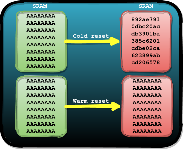
Impact of cold (above) and hot (below) reboots on SRAM content
We decided to find out if the above is true for the ESP32. We found that you can use a hardware watchdog timer to perform a soft hot boot. You can force this timer to fire even when the chip is in boot mode using the UART bootloader. As a result, you can use this mechanism to put the ESP32 into normal boot mode.
Using the test code, which was loaded into SRAM and executed using the UART bootloader, we determined that the data in SRAM, indeed, persists after a hot reset initiated by the watchdog timer. And this means that we, having recorded what we need in SRAM, can boot the ESP32 as usual.
Then the question arose before us about how we can use this.
The road to failure
We assumed that we might be able to take advantage of the fact that data is saved in SRAM after a hot reboot for an attack. Our first attack consisted in the fact that we wrote some code to SRAM using the UART bootloader, and then, using the watchdog timer, we performed a hot reset of the device. We then made a crash by running it while the ROM code overwrites that code with the flash bootloader code during normal boot.
We got this idea after we turned the data transfer process into the code execution process in the course of earlier experiments . Then we noticed that the chip starts executing the code from the start address before the bootloader completes copying.
Sometimes, in order to achieve something, you just need to try it ...
▍Code loaded into SRAM and used to carry out the attack
Here is the code that we wrote to SRAM using the UART bootloader.
#define a "addi a6, a6, 1;"
#define t a a a a a a a a a a
#define h t t t t t t t t t t
#define d h h h h h h h h h h

void __attribute__((noreturn)) call_start_cpu0() {
    uint8_t cmd;

    ets_printf("SRAM CODE\n");

    while (1) {

        cmd = 0;
        uart_rx_one_char(&cmd);

        if(cmd == 'A') {                                    // 1
            *(unsigned int *)(0x3ff4808c) = 0x4001f880;
            *(unsigned int *)(0x3ff48090) = 0x00003a98;
            *(unsigned int *)(0x3ff4808c) = 0xc001f880;
        }
    }

    asm volatile ( d );                                     // 2

    "movi a6, 0x40; slli a6, a6, 24;"                       // 3
    "movi a7, 0x00; slli a7, a7, 16;"
    "xor a6, a6, a7;"
    "movi a7, 0x7c; slli a7, a7, 8;"
    "xor a6, a6, a7;"
    "movi a7, 0xf8;"
    "xor a6, a6, a7;"

    "movi a10, 0x52; callx8  a6;" // R
    "movi a10, 0x61; callx8  a6;" // a
    "movi a10, 0x65; callx8  a6;" // e
    "movi a10, 0x6C; callx8  a6;" // l
    "movi a10, 0x69; callx8  a6;" // i
    "movi a10, 0x7A; callx8  a6;" // z
    "movi a10, 0x65; callx8  a6;" // e
    "movi a10, 0x21; callx8  a6;" // !
    "movi a10, 0x0a; callx8  a6;" // \n

    while(1);
}
This code implements the following (the list item numbers correspond to the numbers specified in the comments):
- A single command command handler that resets the watchdog timer.
- An analogue
NOPbased on instructionsaddi. - Assembly code that outputs a string to the serial interface
Raelize!.
▍Choosing the timing of the attack
We had a relatively small attack window at our disposal, starting with
Fas shown in the following figure. We knew from previous experiments that the bootloader code is being copied from flash memory at this point.
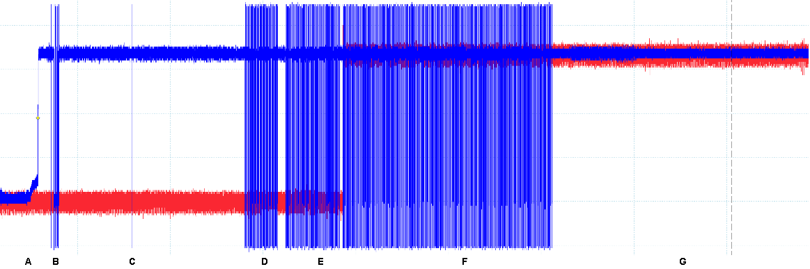
The attack window is represented by F
Failure must be made before the SRAM content is completely overwritten by the correct bootloader code from flash memory.
▍ Attack Cycle
In each of our experiments, we took the following steps to verify that the attack idea worked. The successful organization of the failure should have resulted in the output to the serial line interface
Raelize!.
- Set the pin
G0low and perform a cold boot to enter UART bootloader mode. - Using a command
load_ramto execute attack code from SRAM. - Sends the program
Ato hot reboot and to return to normal boot mode. - Organization of a failure in the process of copying the bootloader from flash memory using the code from ROM.
▍Results
After we performed this experiment for over a day, having carried out it over a million times, we still did not succeed.
▍Unexpected result
But, despite the fact that we did not succeed in achieving what we wanted, we, analyzing the results of the experiments, found something unexpected.
In one experiment, the serial interface reported data indicating that a failure resulted in an exception
IllegalInstruction(invalid instruction). This is how it looked:
ets Jun  8 2016 00:22:57
rst:0x10 (RTCWDT_RTC_RESET),boot:0x13 (SPI_FAST_FLASH_BOOT)
configsip: 0, SPIWP:0xee
clk_drv:0x00,q_drv:0x00,d_drv:0x00,cs0_drv:0x00,hd_drv:0x00,wp_drv:0x00
mode:DIO, clock div:2
load:0x3fff0008,len:4
load:0x3fff000c,len:3220
load:0x40078000,len:4816
load:0x40080400,len:18640
entry 0x40080740
Fatal exception (0): IllegalInstruction
epc1=0x661b661b, epc2=0x00000000, epc3=0x00000000,
excvaddr=0x00000000, depc=0x00000000
When trying to cause a chip failure, these exceptions occur quite often. The same is true for the ESP32. For most of these exceptions, the register is
PCset to the expected value (that is, the correct address is located there). It rarely happens that PCsuch an interesting meaning appears.
The exception is
IllegalInstructionthrown because 0x661b661bthere is no correct instruction at the address . We decided that this value PCmust come from somewhere in the register , and that by itself it cannot appear there.
In search of an explanation, we analyzed the code that we loaded into SRAM. Viewing the binary code, a snippet of which is shown below, allowed us to quickly find out the answer to our question. Namely, it is easy to find the meaning here
0x661b661b... It is represented by two instructions addi a6, a6, 1, with the help of which the analogue is implemented in the code NOP.
00000000  e9 02 02 10 28 04 08 40  ee 00 00 00 00 00 00 00  |....(..@........|
00000010  00 00 00 00 00 00 00 01  00 00 ff 3f 0c 00 00 00  |...........?....|
00000020  53 52 41 4d 20 43 4f 44  45 0a 00 00 00 04 08 40  |SRAM CODE......@|
00000030  50 09 00 00 00 00 ff 3f  04 04 fe 3f 4d 04 08 40  |P......?...?M..@|
00000040  00 04 fe 3f 8c 80 f4 3f  90 80 f4 3f 98 3a 00 00  |...?...?...?.:..|
00000050  80 f8 01 c0 54 7d 00 40  d0 92 00 40 36 61 00 a1  |....T}.@...@6a..|
00000060  f5 ff 81 fc ff e0 08 00  0c 08 82 41 00 ad 01 81  |...........A....|
00000070  fa ff e0 08 00 82 01 00  4c 19 97 98 1f 81 ef ff  |........L.......|
00000080  91 ee ff 89 09 91 ee ff  89 09 91 f0 ff 81 ee ff  |................|
00000090  99 08 91 ef ff 81 eb ff  99 08 86 f2 ff 5c a9 97  |.............\..|
000000a0  98 c5 1b 66 1b 66 1b 66  1b 66 1b 66 1b 66 3e 0c  |...f.f.f.f.f.f>.|
000000b0  1b 66 1b 66 1b 66 1b 66  1b 66 1b 66 1b 66 1b 66  |.f.f.f.f.f.f.f.f|
000000c0  1b 66 1b 66 1b 66 1b 66  1b 66 1b 66 1b 66 1b 66  |.f.f.f.f.f.f.f.f|
000000d0  1b 66 1b 66 1b 66 1b 66  1b 66 1b 66 1b 66 1b 66  |.f.f.f.f.f.f.f.f|
...
00000330  1b 66 1b 66 1b 66 1b 66  1b 66 1b 66 1b 66 1b 66  |.f.f.f.f.f.f.f.f|
00000340  1b 66 1b 66 1b 66 1b 66  1b 66 1b 66 1b 66 1b 66  |.f.f.f.f.f.f.f.f|
00000350  1b 66 1b 66 1b 66 1b 66  1b 66 1b 66 1b 66 1b 66  |.f.f.f.f.f.f.f.f|
We prepared a "wiggle room" with these instructions, using them in a similar way to how sequences of commands
NOPare often used in exploits to delay code execution until the right moment. We didn't expect these instructions to end up in the register PC.
But we, of course, were not against using this. We decided that we could load data from SRAM into a register
PCduring a crash caused when data from flash memory was copied by means of ROM code.
We quickly realized that we now had all the ingredients to prepare an attack that would bypass secure boot and flash encryption systems with a single glitch. Here we used the experience gained during the execution of the previously described attackwhen we managed to get control of the register
PC.
Way to success
For this attack, we used most of the code that was previously loaded into SRAM using the UART bootloader. Only commands for outputting characters to the serial interface have been removed from this code, since now our goal was to set the register
PCto the value we needed, that is, to get the ability to control the system.
#define a "addi a6, a6, 1;"
#define t a a a a a a a a a a
#define h t t t t t t t t t t
#define d h h h h h h h h h h

void __attribute__((noreturn)) call_start_cpu0() {
    uint8_t cmd;

    ets_printf("SRAM CODE\n");

    while (1) {

        cmd = 0;
        uart_rx_one_char(&cmd);

        if(cmd == 'A') {
            *(unsigned int *)(0x3ff4808c) = 0x4001f880;
            *(unsigned int *)(0x3ff48090) = 0x00003a98;
            *(unsigned int *)(0x3ff4808c) = 0xc001f880;
        }
    }

    asm volatile ( d );

    while(1);
}
After compiling this code, we, right in its binary version, replaced the instructions
addiwith an address 0x4005a980. At this address is a function in ROM that outputs data to the serial interface. A successful call to this function would let us know about a successful attack.
We prepared ourselves to handle failures that were consistent with what caused the exception in a previous experiment
IllegalInstruction. After a while, we discovered the successful completion of several experiments to load the PCgiven address into the register . The case control is PChighly likely to mean that we can execute arbitrary code.
▍Why is this possible?
The title of this section contains a good question that is not easy to answer.
Unfortunately, we do not have a clear answer. We certainly didn't expect data manipulation to allow register control
PC. We have several explanations for this, but we cannot claim with complete certainty that any of them are true.
One explanation is that during a failure, both operands of the instruction
ldrused to load the value into a0. This is similar to what we saw in this attack, where we gained indirect control over the register PCby modifying the data.
Moreover, it is possible that the code stored in ROM implements functionality that contributes to the success of this attack. In other words, due to a failure, we can execute the correct code from ROM, which leads to the fact that the data from SRAM is loaded into the register
PC.
In order to find out what exactly enabled us to perform this attack, we need to do more research. But if you look at the matter through the eyes of someone who decided to hack the chip, we have enough knowledge to create an exploit based on the possibility of influencing the register
PC.
Extract the contents of flash memory as plain text
We can write to the register
PCwhat we want, but we cannot yet retrieve the contents of the flash memory as plain text. Therefore, it was decided to take advantage of the UART bootloader capabilities.
Namely, we decided to go straight to the UART bootloader while the chip is in normal boot mode. To carry out this attack, we rewrote the instructions
addiin the code loaded into RAM, using the UART bootloader code start address ( 0x40007a19) instead .
The UART bootloader outputs the line shown below to the serial interface. We can use this fact to determine the success of an attack.
waiting for download\n"
Once this experiment is successful, we can simply use it
esptool.pyto run the command read_memand access the plain text data in the flash memory. For example, the following command reads 4 bytes from the external flash address space ( 0x3f400000).
esptool.py --no-stub --before no_reset --after no_reset read_mem 0x3f400000
Unfortunately, such a command didn't work. For some reason, the processor's response looked like
0xbad00bad, indicating that we are trying to read data from unallocated memory.
esptool.py v2.8
Serial port COM8
Connecting....
Detecting chip type... ESP32
Chip is ESP32D0WDQ6 (revision 1)
Crystal is 40MHz
MAC: 24:6f:28:24:75:08
Enabling default SPI flash mode...
0x3f400000 = 0xbad00bad
Staying in bootloader.
We noticed that quite a lot of settings are made at the beginning of the UART bootloader. We assumed that these settings might affect the MMU as well.
Just to try something else, we decided to go straight to the command handler of the UART (
0x40007a4e) bootloader itself . After we find ourselves in the handler, we can independently send the command read_memdirectly to the serial interface:
target.write(b'\xc0\x00\x0a\x04\x00\x00\x00\x00\x00\x00\x00\x40\x3f\xc0')
Unfortunately, if you go straight to the handler, then the line that is displayed after entering the UART bootloader (that is -
waiting for download\n) will not be displayed. Because of this, we lose a simple and convenient way to identify successful experiments. As a result, we decided to send the above command in all experiments, regardless of whether they were successful or not. We used a very short serial timeout in order to minimize the additional timeout associated with this timeout, which is almost always the case.
After a while, we saw the results of the first successful experiments!
Outcome
In this article, we described an attack on ESP32, in which we bypass the secure boot and encryption systems of flash memory, arranging only one failure in the microcontroller. Moreover, we used a vulnerability exploited during the attack to extract the contents of encrypted flash memory in plain text.
We can use FIRM to step through this attack .
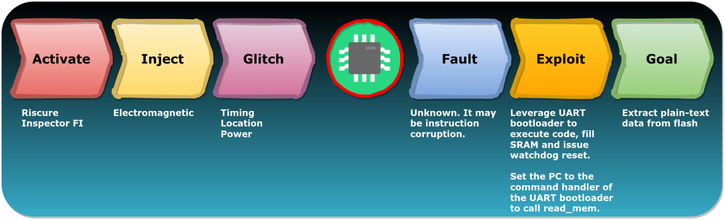
Attack Progress
Here is a brief description of what happens in the different steps of the above attack:
- Activate (the choice of tools for carrying out an attack) - the Riscure Inspector FI complex is used here .
- Inject (attack) - an electromagnetic effect is carried out on the microcontroller under investigation.
- Glitch ( ) — , (, , ).
- Fault ( ) — , , , . , - .
- Exploit ( ) — UART , SRAM, . UART
PCread_mem. - Goal ( ) — - .
Interestingly, the success of this attack depends on two weaknesses in the ESP32. The first weakness is that the UART bootloader cannot be disabled. As a result, it is always available. The second weakness is the persistence of data in SRAM after a hot reset of the device. This allows using the UART bootloader to fill the SRAM with arbitrary data.
In an information report , which refers to the attack, the company Espressif reports that newer versions ESP32 there are mechanisms that make such an attack impossible.
All standard embedded systems are vulnerable to device disruption attacks. Therefore, it is not surprising that the ESP32 microcontroller is also vulnerable to side channel attacks. Chips like these are simply not designed to withstand such attacks. But, importantly, this does not mean that such attacks do not carry any risk.
Our research has shown that exploiting the weaknesses of the chip allows for successful attacks, causing failures. Most attacks that can be learned about from open sources use traditional approaches, where the main focus is on bypassing checks. We haven't seen very many reports of attacks like the one we've described.
We are confident that the full potential of such attacks is still not fully explored. Until recently, most researchers have only been studying methods of disrupting the operation of chips (steps Activate, Inject, Glitch), but we went further, considering the possibility of working with a vulnerable chip after a failure (steps Fault, Exploit, Goal).

Research to 2020 and beyond 2020
We are confident that creative use of new chip failure models will lead to an increase in attack methods that use interesting vulnerability exploitation strategies to achieve a wide variety of goals.
If you are interested in the topic raised in this material, then here , here and here - other materials devoted to the study of the ESP32.
Have you encountered in practice hacking any devices using methods similar to those discussed in this article?