Surely many of you have ridden a motorcycle, and someone even owns it. Maybe you've been to the karting track and competed with excitement on the track to the whistle of rubber and the roar of the engine. Or maybe you just equip the dacha on weekends with a gasoline tool. In these and many other cases, we are dealing with small internal combustion engines controlled by a carburetor. But what is this detail? What is it for and what does it consist of? What characteristics are affected, how are they regulated? You can find answers to these and a number of other questions in this article.
Let's concretize the questions that are considered in the course of the story.
- .
- , .
- .
- , .
- , , .
- , .
Today we will consider only the first part. In view of the large volume of material proposed for study, parts of the article will be formed as separate publications.
PS I understand that this kind of material is only indirectly related to the topic of the portal. However, here in the category of transport there are also articles devoted to a home-made two-stroke internal combustion engine and even a steam engine . These examples motivated me to publish the work. In addition, a publication on such an authoritative and well-indexed resource as Habr will help spread the material and convey it to an audience interested directly in carburetors. Happy and, I hope, useful reading, everyone!
Carburetor: basic principles
Otto cycle motorcycle engines, both two-stroke and four-stroke, consume fuel that evaporates readily and has anti-knock properties to mix with hot air before the spark plug initiates ignition. These fuels include, for example, commercial gasoline, special competition gasoline, methanol and ethyl alcohol.
The mixing process takes place in a completely different way in engines operating on the Diesel cycle. They use less volatile fuel, the anti-knock properties of which require mixing with air directly in the combustion chamber, in which the pressure and temperature correspond to the parameters of the fuel's self-ignition.
For this reason, the power of a diesel engine can be controlled by adjusting only the fuel supply, without the need for air flow control. In engines operating on the Otto cycle, both the amount of air and the amount of fuel consumed by the engine must be controlled during the mixture formation process.
Most automotive engines use a centrally controlled fuel injection system. The control unit regulates the open time of the injector, during which fuel flows into the air stream. Similar systems have been adapted for some high-end motorcycle engines. However, the use of carburetors is still relevant.
The peculiarity of the principle of operation of the carburetor lies in the fact that the outflow of fuel occurs under the action of a vacuum through the nozzle system. Therefore, carburetors are designed based on three main functions:
- Engine power management according to the driver's needs by changing the air flow;
- Metering the fuel supply to the air flow while maintaining the optimal air-to-fuel ratio throughout the entire operating range of engine speed;
- Homogenizing the air / fuel mixture for proper ignition and combustion.
The composition of the air-fuel mixture
Fuel Ratio (A / F) is the mass ratio of air to fuel that the engine consumes. It is defined as
From a chemical point of view, this ratio should be stoichiometric, i.e. must ensure complete combustion without excess air (lean mixture) or unburned fuel residues (rich mixture).
Stoichiometric composition
The numerical value of the stoichiometric ratio depends on the type of fuel. For commercial gasoline, it ranges from 14.5 to 14.8. This means that for complete combustion of one part of gasoline, 14.5-14.8 parts of air are required. For engines running on methanol, this ratio drops to 6.5, while for ethyl alcohol it is 9.
Real mix composition
The mixture produced by the carburetor while the engine is running does not have to be stoichiometric. Depending on the design of the engine and the conditions of its operation (the number of revolutions and the magnitude of the load), part of the fuel may not burn, for whatever reason does not get into the combustion chamber or due to the imperfect combustion process. A change in the composition of the mixture can be caused by residual combustion products in the cylinder, as well as a partial loss of fresh charge of the mixture through the exhaust system. Two-stroke engines are especially sensitive to composition changes.
If we consider the charge of the mixture, which is directly involved in combustion, we can come to the conclusion that its composition should be richer than stoichiometric to compensate for the above phenomena.
The composition of the mixture depending on the working conditions
The composition of the mixture should vary within certain limits, depending on the operating conditions of the engine. It has been established that, in the general case, the composition of the mixture should be richer at idle, in the acceleration mode and in the maximum power mode. On the contrary, in the steady state the composition can be poorer, i.e. the air to fuel ratio can be increased compared to other operating modes.
As applied to two-stroke engines, the concepts of lean and rich are usually not associated with stoichiometric ratio, since they constantly operate on a mixture richer than stoichiometric. This is true for many four-stroke engines, but they generally run on a leaner mixture than two-stroke engines.
Fuel supply system to the carburetor
Principle of operation
A design variant of the fuel supply system is shown in the figure.
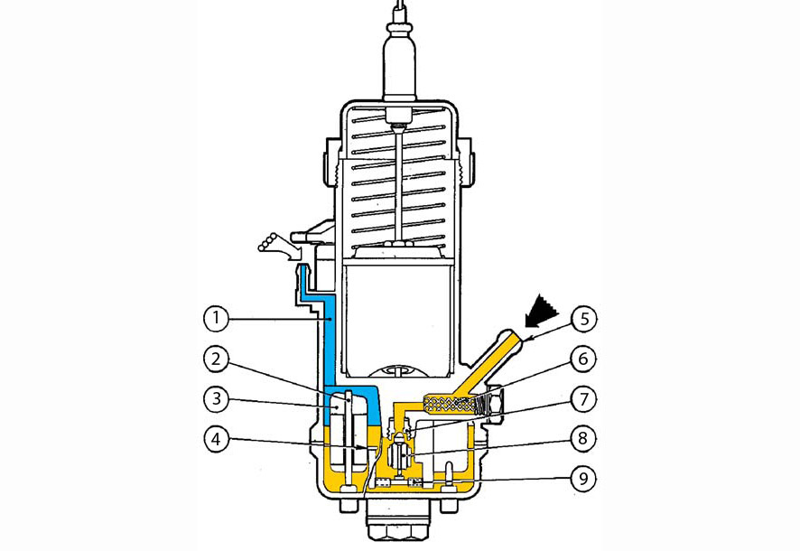
Fuel supply system to the carburetor: 1 - channel connecting the float chamber to the atmosphere; 2 - float guide; 3 - float; 4 - lever of interaction with the fuel valve; 5 - fuel supply union; 6 - mesh filter; 7 - valve seat; 8 - valve needle; 9 - the rolling axis of the lever 4
The fuel coming from the tank is kept at a constant level inside the float chamber. The float and the associated valve are responsible for this. The float moves freely with the fuel level, thereby adjusting the flow area of the valve. As the engine consumes fuel, the level in the float chamber decreases, the float goes down and opens the valve, thereby allowing fuel to flow from the tank. The fuel level begins to rise, the float rises and closes the valve at a certain point, after which the process is repeated.
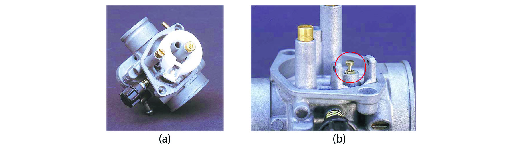
General view of the float chamber (a), fuel valve (b)
Thus, it is possible to maintain an almost constant fuel pressure on the various jets. In other words, the height that the fuel needs to rise to start spraying under vacuum remains constant. The illustration shows a cross-section of the carburetor showing the main systems. The fuel level maintained in the float chamber is highlighted in yellow.
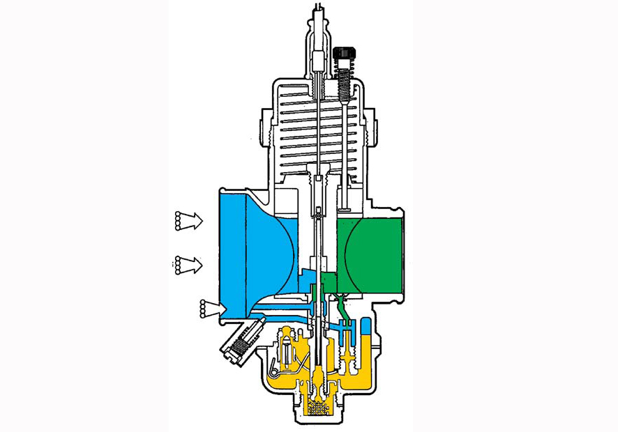
Cutaway carburetor showing the main systems
Design and adjustment methods
Let's consider in more detail the system: float - valve.
The fuel valve consists of a shut-off needle and a seat pressed or screwed into the carburetor body. The needle tip is rubberized. The rubber composition is well compatible with commercial gasoline, but when using specialized fuels, such as alcoholic fuels, you must ensure compatibility with the seal materials in order to deteriorate the quality of the carburetor. Many locking needle designs use a spring-loaded follower that interacts with a float to reduce needle vibration generated by motorcycle movement and fuel movement in the float chamber.
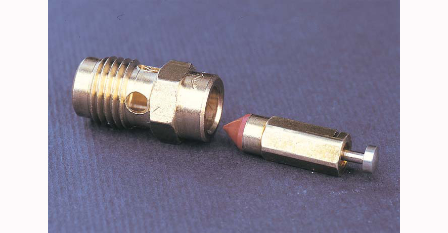
Fuel valve
The flow area of the fuel valve is a control parameter, since it determines the maximum fuel consumption. If the cross-section is too small, the float chamber may empty because the fuel consumption will be higher than the input under the current engine operating conditions (usually at full load). After working for some time in this mode, the engine may fail due to depletion of the combustible mixture.
The fuel level is also an adjustment parameter of the carburetor, which follows from the principle of operation, since the dosage of fuel consumption changes with the level, thereby affecting the composition of the mixture.
The fuel level is adjusted by changing two parameters:
- float weight;
- the geometry of the lever connecting the float to the valve.
Installing a heavier float will raise the fuel level due to compensation for its lower buoyancy. This will lead to a richer mixture if the other parameters are not changed. In the opposite situation, when a lighter float is installed, the fuel level will decrease due to a decrease in buoyancy. This will lead to early closure of the valve and rebuilding the carburetor to a leaner mixture. Therefore, floats are classified by weight and must be set to the appropriate height according to the prescribed standards.
The way to control the height of the floats is shown in the figure. When it is necessary to adjust the level and it is not possible to change the weight of the float, you can change the geometry of the lever acting on the valve. In this case, the float will close the valve earlier (at a lower level) or later (at a higher level) at the same weight.
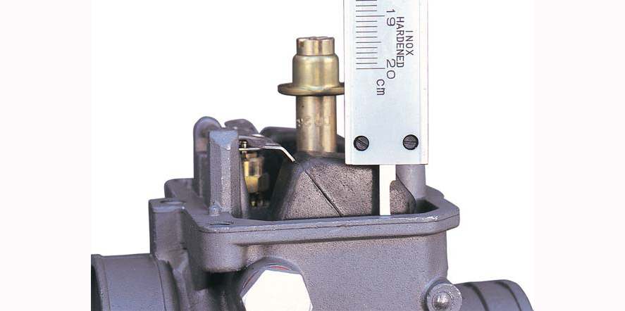
Measuring the float height
Features of working conditions
A high fuel level, just like a low one, affects the operation of all carburetor systems in all engine operating modes. However, it should be noted that too low a fuel level in the float chamber can lead to insufficient fuel pressure on the nozzles, which will cause an over-depletion of the mixture dangerous for engine operation. This can happen when fuel moves inside the float chamber during accelerations to which the vehicle is subjected. In this case (which mostly happens on off-road or track bikes when cornering and hard braking), if the level is too low, any jet can suddenly become airy.
To prevent such a situation, some designs use special deflectors around the nozzles, they are also called dampers (an example of such a device will be given in the next publication). The purpose of the damper is to keep as much fuel close to the jet as possible under all possible operating conditions.
To be continued...