Greetings, Habr community. Recently, our company launched the IRIS measuring and control device on the market. As the main programmer of this project, I want to tell you about the development of the device firmware (According to the project manager, the firmware is no more than 30% of the total work from idea to mass production). The article will be primarily useful for novice developers in terms of understanding the labor costs of a "real" project and users who want to "look under the hood."
Purpose of the device
IRIS is a multifunctional measuring device. He knows how to measure current (ammeter), voltage (voltmeter), power (wattmeter) and a number of other quantities. KIP IRIS remembers their maximum values, writes oscillograms. A detailed description of the device can be found on the company's website.
A bit of statistics
Timing
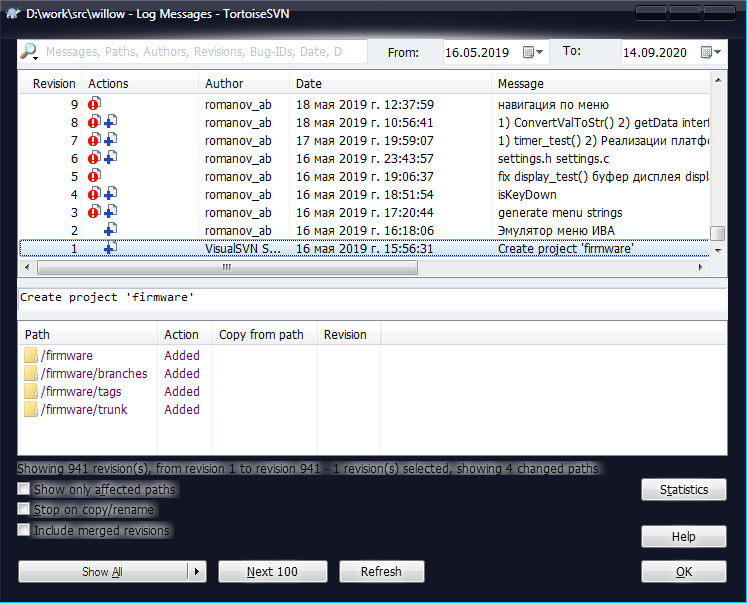
First commit to SVN: May 16, 2019.
Release: June 19, 2020.
* This is calendar time, not full-time development throughout the term. There were distractions for other projects, expectations of technical specifications, hardware iterations, etc.
Commits
Number in SVN: 928
Where does this come from?
1) I am a supporter of microcommitting during development
2) Duplicates in branches for hardware and emulator
3) Documentation
So, the number with a payload in the form of a new code (trunk branch) is not more than 300.
Number of lines of code
Statistics were collected by the cloc utility with default parameters, excluding the HAL STM32 and ESP-IDF ESP32 sources.
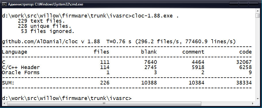
STM32 firmware: 38,334 lines of code. Of which:
60870-5-101: 18751
ModbusRTU: 3859
Oscilloscope: 1944
Archiver: 955
ESP32 firmware: 1537 lines of code.
Hardware components (peripherals involved)
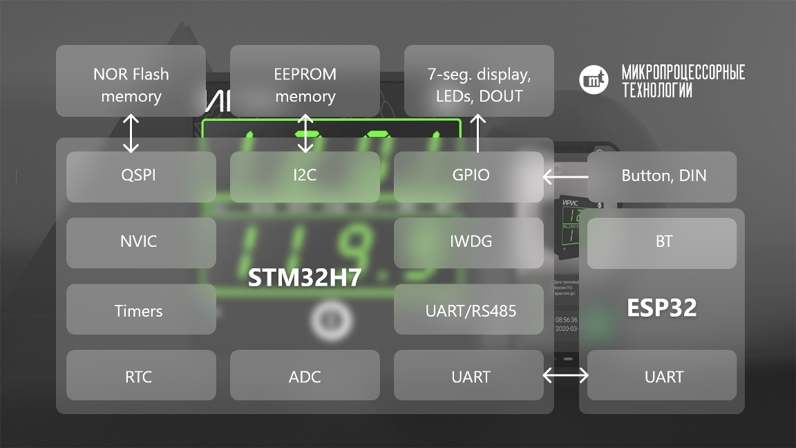
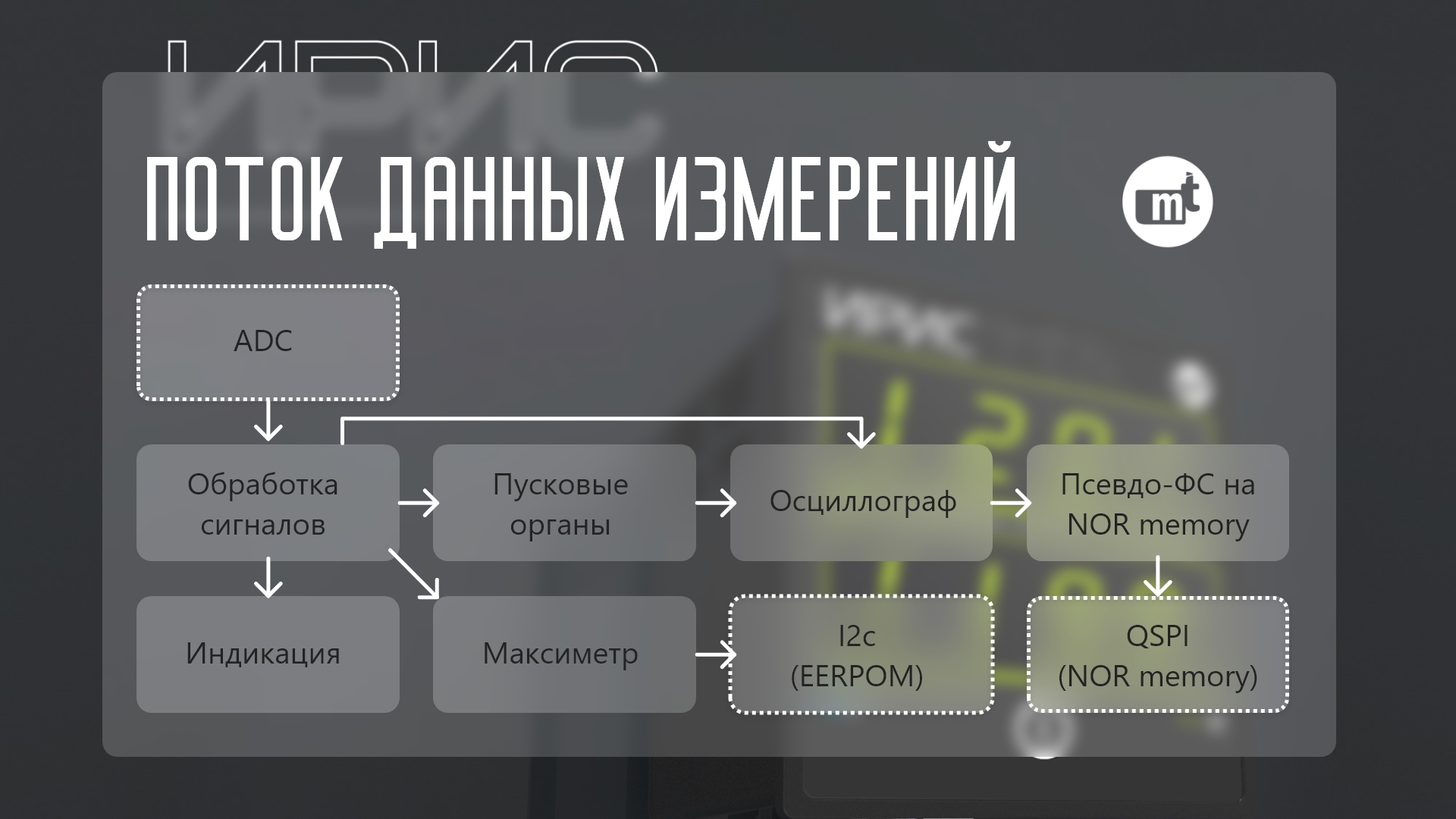
The main functions of the device are implemented in the STM32 firmware. The ESP32 firmware is responsible for Bluetooth communication. Communication between the chips is carried out via the UART (see the figure in the header).
NVIC is an interrupt controller.
IWDG - watchdog timer for restarting the chip in case of firmware hangup.
Timers - Timer interrupts keep the project heartbeat.
EEPROM - memory for storing production information, settings, maximum readings, ADC calibration coefficients.
I2C is an interface for accessing the EEPROM chip.
NOR - memory for storing waveforms.
QSPI is an interface for accessing the NOR memory chip.
RTC - the real time clock ensures the course of time after the device is turned off.
ADC - ADC.
RS485 is a serial interface for connection via ModbusRTU and 60870-101 protocols.
DIN, DOUT - discrete input and output.
Button - a button on the front panel of the device for switching the indication between measurements.
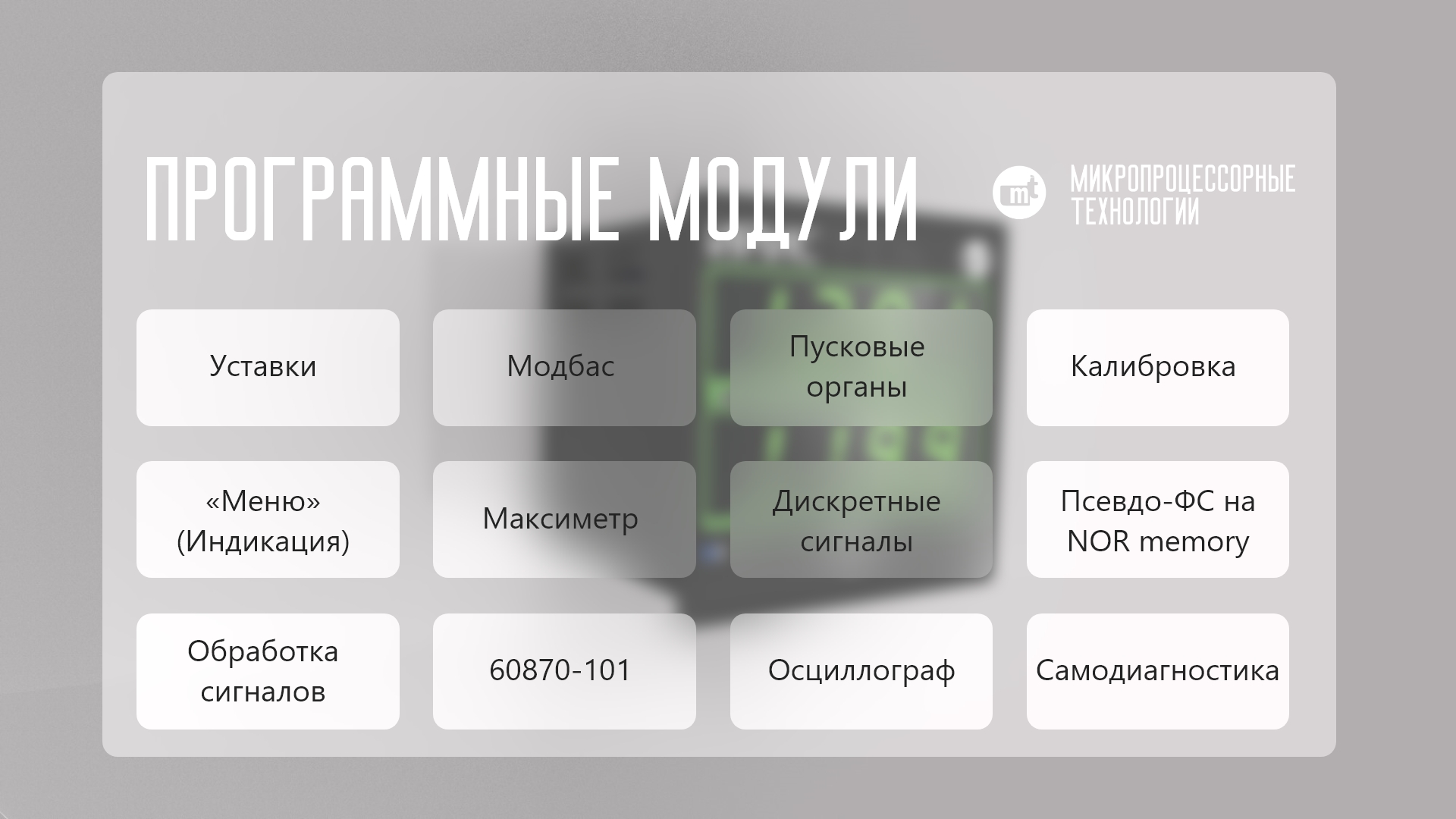
Software architecture
Main software modules
Measurement data stream
operating system
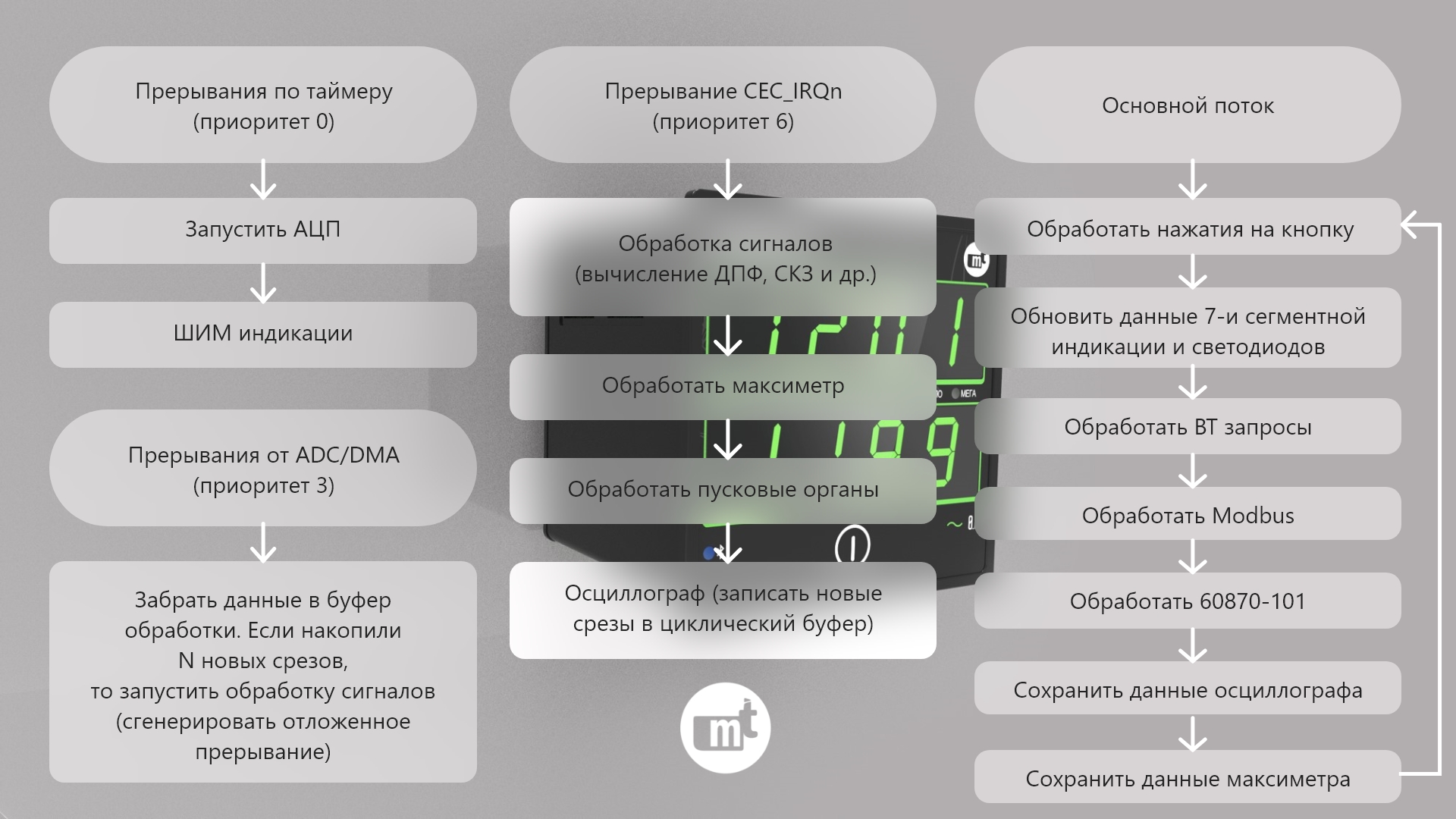
Taking into account the limitations of the amount of flash memory (OS introduces overhead) and the relative simplicity of the device, it was decided to abandon the use of the operating system and get by with interrupts. This approach has already been highlighted in articles on Habré more than once, so I will give only flowcharts of tasks inside interrupts with their priorities.
Sample code. Delayed interrupt generation in STM32.
//     6
  HAL_NVIC_SetPriority(CEC_IRQn, 6, 0);
  HAL_NVIC_EnableIRQ(CEC_IRQn);

//
HAL_NVIC_SetPendingIRQ(CEC_IRQn);

//
void CEC_IRQHandler(void) {
// user code
}
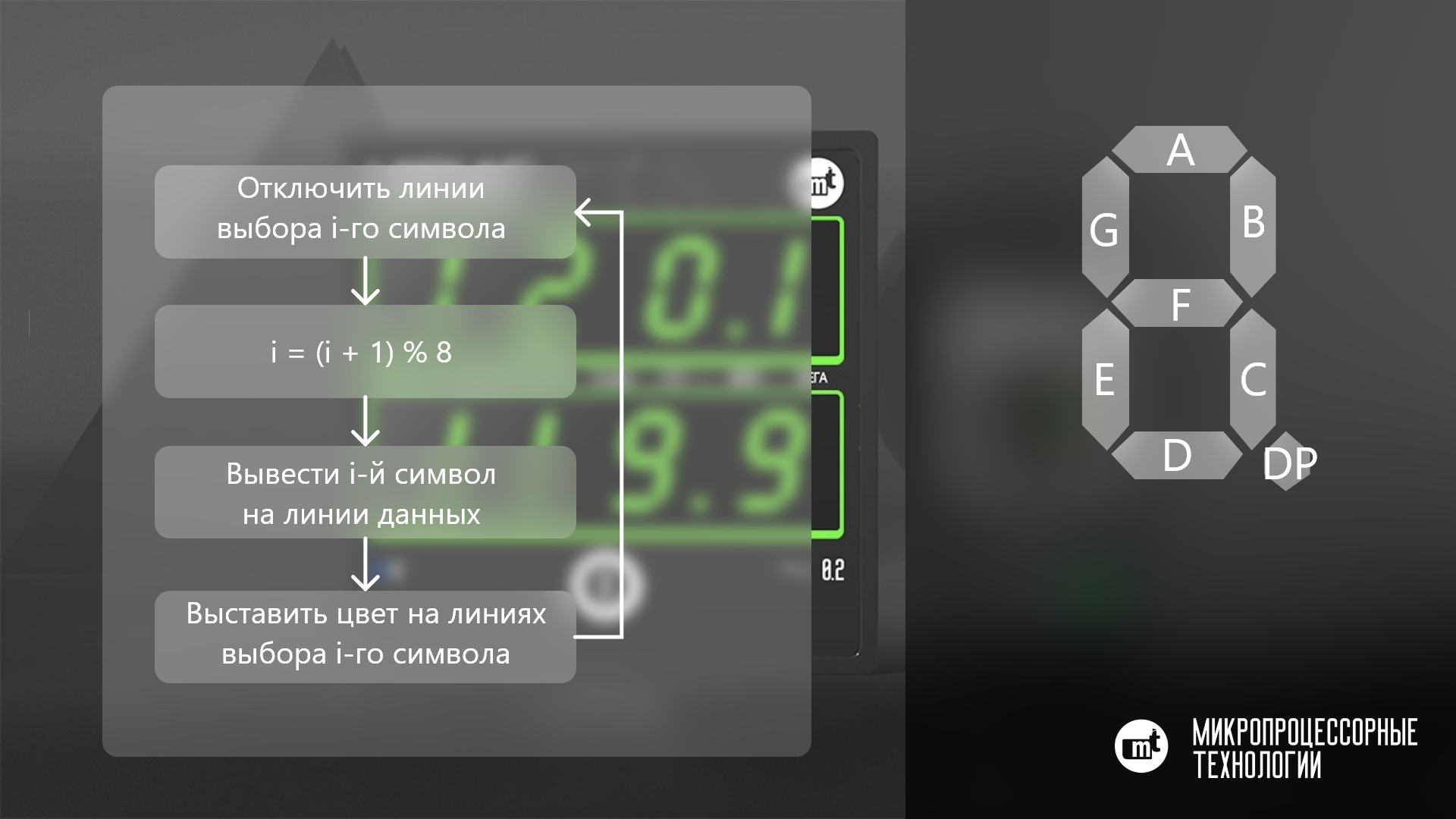
PWM 7 segment display
The device has two lines of 4 characters each, a total of 8 indicators. The 7 segment displays have 8 parallel data lines (A, B, C, D, E, F, G, DP) and 2 color selection lines (green and red) for each.
Waveform storage
The storage is organized on the principle of a circular buffer with 64 KB slots per waveform (fixed size).
Ensuring data consistency in the event of an unexpected shutdown
In EEPROM, data is written in two copies with an added checksum at the end. If at the moment of data recording the device is turned off, then at least one copy of the data will remain intact. The checksum is also added to each slice of the oscilloscope data (measured values at the ADC inputs), so an invalid checksum of the slice will be a sign of the end of the oscillogram.
Automatic generation of software version
1) Create the version.fmt file:
#define SVN_REV ($ WCREV $)
2) Before building the project, add the command (for System Workbanch):
SubWCRev $ {ProjDirPath} $ {ProjDirPath} /version.fmt $ {ProjDirPath} /version.h
After executing this command, a version.h file will be created with the last commit number.
There is a similar utility for GIT: GitWCRev. /version.fmt ./main/version.h
#define GIT_REV ($ WCLOGCOUNT $)
This allows you to unambiguously match commit and software version.
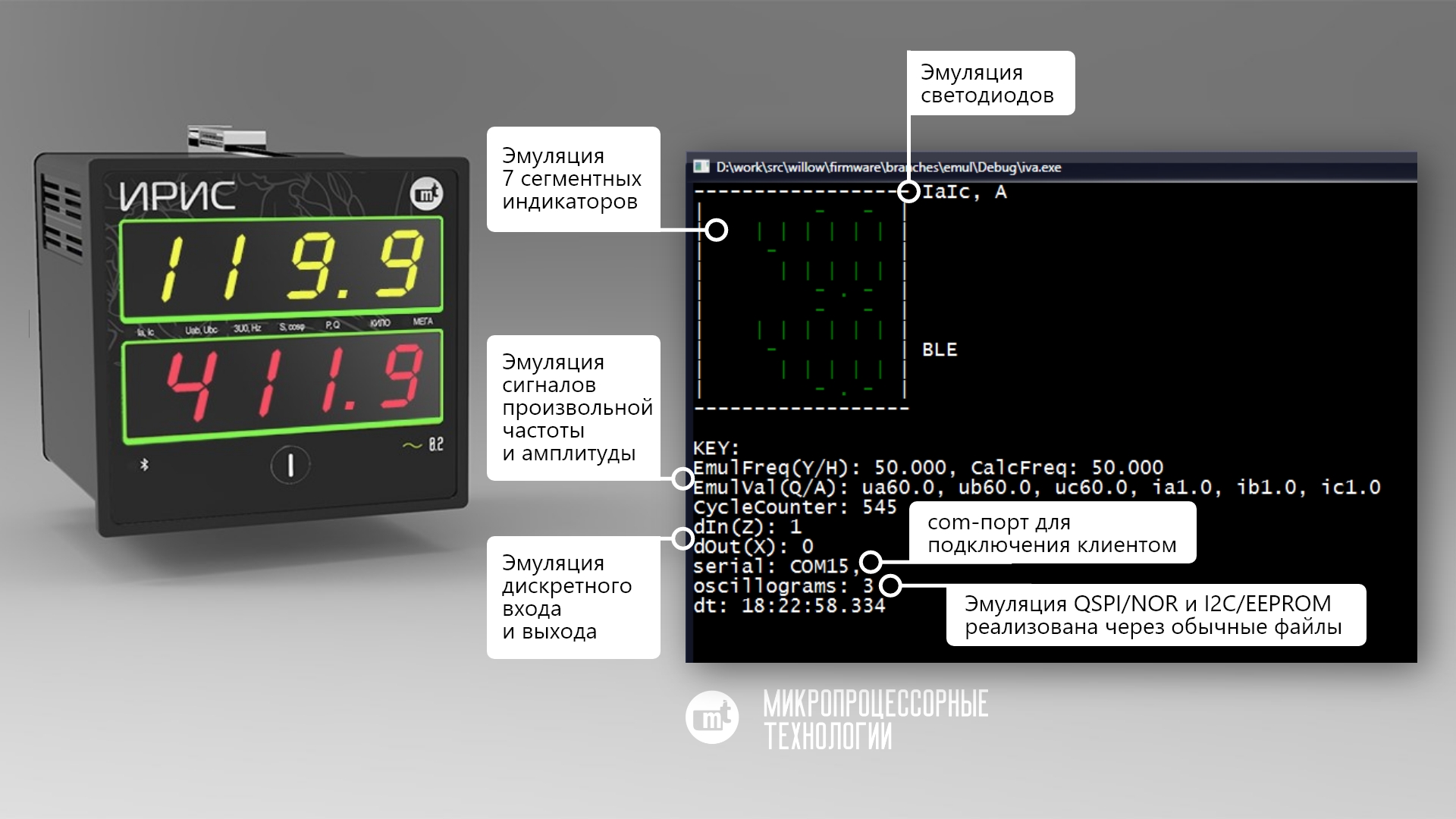
Emulator
Because the development of the firmware began before the appearance of the first instance of hardware, then part of the code began to write as a console application on a PC.
Advantages:
- development and debugging for a PC is easier than directly on the hardware.
- the ability to generate any input signals.
- the ability to debug the client on a PC without hardware. The com0com driver is installed on the PC, which creates a pair of com ports. One of them starts the emulator, and the other connects the client.
- contributes to beautiful architecture, because you have to select the interface of hardware-dependent modules and write two implementations
Sample code. Two implementations of reading data from eeprom.
uint32_t eeprom_read(uint32_t offset, uint8_t * buf, uint32_t len);
ifdef STM32H7
uint32_t eeprom_read(uint32_t offset, uint8_t * buf, uint32_t len)
{
  if (diag_isError(ERR_I2C))
    return 0;
	if (eeprom_wait_ready()) {
		HAL_StatusTypeDef status = HAL_I2C_Mem_Read(&I2C_MEM_HANDLE, I2C_MEM_DEV_ADDR, offset, I2C_MEMADD_SIZE_16BIT, buf, len, I2C_MEM_TIMEOUT_MS);
		if (status == HAL_OK)
			return len;
	}
	diag_setError(ERR_I2C, true);
  return 0;
}
#endif
#ifdef _WIN32
static FILE *fpEeprom = NULL;
#define EMUL_EEPROM_FILE "eeprom.bin"
void checkAndCreateEpromFile() {
	if (fpEeprom == NULL) {
		fopen_s(&fpEeprom, EMUL_EEPROM_FILE, "rb+");
		if (fpEeprom == NULL)
			fopen_s(&fpEeprom, EMUL_EEPROM_FILE, "wb+");
		fseek(fpEeprom, EEPROM_SIZE, SEEK_SET);
		fputc('\0', fpEeprom);
		fflush(fpEeprom);
	}
}
uint32_t eeprom_read(uint32_t offset, uint8_t * buf, uint32_t len)
{
	checkAndCreateEpromFile();
	fseek(fpEeprom, offset, SEEK_SET);
	return (uint32_t)fread(buf, len, 1, fpEeprom);
}
#endif
Acceleration of data transfer (archiving)
To increase the speed of downloading waveforms, they were archived before sending. The uzlib library was used as an archiver . Unpacking this format in C # is done in a couple of lines of code.
Sample code. Data archiving.
#define ARCHIVER_HASH_BITS (12)
uint8_t __RAM_288K archiver_hash_table[sizeof(uzlib_hash_entry_t) * (1 << ARCHIVER_HASH_BITS)];

bool archive(const uint8_t* src, uint32_t src_len, uint8_t* dst, uint32_t dst_len, uint32_t *archive_len)
{
	struct uzlib_comp comp = { 0 };
	comp.dict_size = 32768;
	comp.hash_bits = ARCHIVER_HASH_BITS;
	comp.hash_table = (uzlib_hash_entry_t*)&archiver_hash_table[0];
	memset((void*)comp.hash_table, 0, sizeof(archiver_hash_table));
	comp.out.outbuf = &dst[10]; // skip header 10 bytes
	comp.out.outsize = dst_len - 10 - 8; // skip header 10 bytes and tail(crc+len) 8 bytes
	comp.out.is_overflow = false;

	zlib_start_block(&comp.out);
	uzlib_compress(&comp, src, src_len);
	zlib_finish_block(&comp.out);
	if (comp.out.is_overflow)
		comp.out.outlen = 0;

	dst[0] = 0x1f;
	dst[1] = 0x8b;
	dst[2] = 0x08;
	dst[3] = 0x00; // FLG
	// mtime
	dst[4] =
		dst[5] =
		dst[6] =
		dst[7] = 0;
	dst[8] = 0x04; // XFL
	dst[9] = 0x03; // OS

	unsigned crc = ~uzlib_crc32(src, src_len, ~0);
	memcpy(&dst[10 + comp.out.outlen], &crc, sizeof(crc));
	memcpy(&dst[14 + comp.out.outlen], &src_len, sizeof(src_len));
	*archive_len = 18 + comp.out.outlen;

	if (comp.out.is_overflow)
		return false;
	return true;
}
Sample code. Unpacking data.
// byte[] res; //
                        using (var msOut = new MemoryStream())
                        using (var ms = new MemoryStream(res))
                        using (var gzip = new GZipStream(ms, CompressionMode.Decompress))
                        {
                            int chunk = 4096;
                            var buffer = new byte[chunk];
                            int read;
                            do
                            {
                                read = gzip.Read(buffer, 0, chunk);
                                msOut.Write(buffer, 0, read);
                            } while (read == chunk);

                            //msOut.ToArray();//
                        }
About permanent changes in the TK
Meme from the Internet:
- But you approved the terms of reference!
- Technical task? We thought TK was a "Point of View", and we have several of them.
Sample code. Keyboard handling.
enum {
	IVA_KEY_MASK_NONE,
	IVA_KEY_MASK_ENTER = 0x1,
	IVA_KEY_MASK_ANY   = IVA_KEY_MASK_ENTER,
}IVA_KEY;
uint8_t keyboard_isKeyDown(uint8_t keyMask) {
	return ((keyMask & keyStatesMask) == keyMask);
}
After looking at such a piece of code, you might think why he piled it all up, if there is only one button in the device? In the first version of the TK there were 5 buttons and with the help of them it was planned to implement the editing of the settings directly on the device:
enum {
	IVA_KEY_MASK_NONE  = 0,
	IVA_KEY_MASK_ENTER = 0x01,
	IVA_KEY_MASK_LEFT  = 0x02,
	IVA_KEY_MASK_RIGHT = 0x04,
	IVA_KEY_MASK_UP    = 0x08,
	IVA_KEY_MASK_DOWN  = 0x10,
	IVA_KEY_MASK_ANY   = IVA_KEY_MASK_ENTER | IVA_KEY_MASK_LEFT | IVA_KEY_MASK_RIGHT | IVA_KEY_MASK_UP | IVA_KEY_MASK_DOWN,
}IVA_KEY;
So, if you find an oddity in the code, then you do not need to immediately remember the previous programmer with bad words, perhaps at that time there were reasons for such an implementation.
Some development problems
The flush is over
The microcontroller has 128 KB of flash memory. At some point, the debug build exceeded this volume. I had to enable optimization by volume -Os. If debugging on hardware was required, then a special assembly was made with the disabling of some software modules (modbas, 101st).
QSPI data error
Sometimes, when reading data via qspi, an "extra" byte appeared. The problem disappeared after increasing the priority of the qspi interrupts.
Oscilloscope data error
Because data is sent by DMA, the processor may not "see" it and read old data from the cache. You need to perform cache validation.
Sample code. Cache validation.
//           QSPI/DMA
SCB_CleanDCache_by_Addr((uint32_t*)(((uint32_t)&data[0]) & 0xFFFFFFE0), dataSize + 32);
//    ADC/DMA      CPU
SCB_InvalidateDCache_by_Addr((uint32_t*)&s_pAlignedAdcBuffer[0], sizeof(s_pAlignedAdcBuffer));
ADC problems (different readings from turn on to turn on)
From switching on to switching on, a different offset of the current readings (of the order of 10-30 mA) appeared in the device. The solution was helped by colleagues from Kompel in the person of Vladislav Barsov and Alexander Kvashin for which many thanks to them.
Sample code. ADC initialization.
//
HAL_ADCEx_Calibration_SetValue (&hadc1, ADC_SINGLE_ENDED, myCalibrationFactor[0]);
HAL_ADCEx_Calibration_SetValue (&hadc1, ADC_DIFFERENTIAL_ENDED, myCalibrationFactor[1]);
HAL_ADCEx_LinearCalibration_SetValue (&hadc1, &myLinearCalib_Buffer[0]);
Backlight indication
On the "empty" 7-segment indicators, instead of a complete shutdown, a weak illumination appeared. The reason is that in the real world the waveform is not perfect, and if you ran the code gpio_set_level (0), it does not mean that the signal level immediately changed. The flare was eliminated by adding a PWM to the data lines.
Uart error in HAL
After an Over-Run error occurred, the UART stopped working. The problem was fixed with the HAL patch:
Sample code. Patch for HAL.
---    if (((isrflags & USART_ISR_ORE) != 0U)
---        && (((cr1its & USART_CR1_RXNEIE_RXFNEIE) != 0U) ||
---            ((cr3its & (USART_CR3_RXFTIE | USART_CR3_EIE)) != 0U)))
+++    if ((isrflags & USART_ISR_ORE) != 0U)
    {
      __HAL_UART_CLEAR_FLAG(huart, UART_CLEAR_OREF);
Accessing unaligned data
The error manifested itself only on hardware in an assembly with the -Os optimization level. Instead of real data, the modbus client read zeros.
Sample code. Error reading unaligned data.
	float f_value;
	uint16_t registerValue;
	//     registerValue  0
	//registerValue = ((uint16_t*)&f_value)[(offsetInMaximeterData -
	//	offsetof(mbreg_Maximeter, primaryValue)) / 2];

	//     memcpy
    memcpy(& registerValue, ((uint16_t*)&f_value) + (offsetInMaximeterData -
        offsetof(mbreg_Maximeter, primaryValue)) / 2, sizeof(uint16_t));
Finding the causes of HardFault
One of the exception localization tools I use is watchpoints. I scatter watchpoints around the code, and after the exception appears, I connect with the debugger and see what point the code has passed.
Sample code. SET_DEBUG_POINT (__ LINE__).
//debug.h
#define USE_DEBUG_POINTS
#ifdef USE_DEBUG_POINTS
//     SET_DEBUG_POINT1(__LINE__)
void SET_DEBUG_POINT1(uint32_t val);
void SET_DEBUG_POINT2(uint32_t val);
#else
#define SET_DEBUG_POINT1(...)
#define SET_DEBUG_POINT2(...)
#endif

//debug.c
#ifdef USE_DEBUG_POINTS
volatile uint32_t dbg_point1 = 0;
volatile uint32_t dbg_point2 = 0;
void SET_DEBUG_POINT1(uint32_t val) {
  dbg_point1 = val;
}
void SET_DEBUG_POINT2(uint32_t val) {
  dbg_point2 = val;
}
#endif

//     :
SET_DEBUG_POINT1(__line__);
Tips for beginners
1) Take a look at the code examples. For esp32, examples are included with the SDK. For stm32 in HAL storage STM32CubeMX \ STM32Cube_FW_H7_V1.7.0 \ Projects \ NUCLEO-H743ZI \ Examples \
2) Google: programming manual <your chip>, technical reference manual <your chip>, application note <your chip>, datasheet <your chip>.
3) If you have any technical difficulties and the top 2 points did not help, then you should not neglect contacting support, but rather to distributors who have direct contact with the engineers of the manufacturer's company.
4) Bugs are not only in your code, but also in the manufacturer's HAL.
Thank you for attention.