Recently, a description of the original DIY project based on Raspberry Pi and LED panels appeared on the network . The goal of the project is to visualize the load level of the PC processor. For this, animation on the LED panels of a homemade device is used.
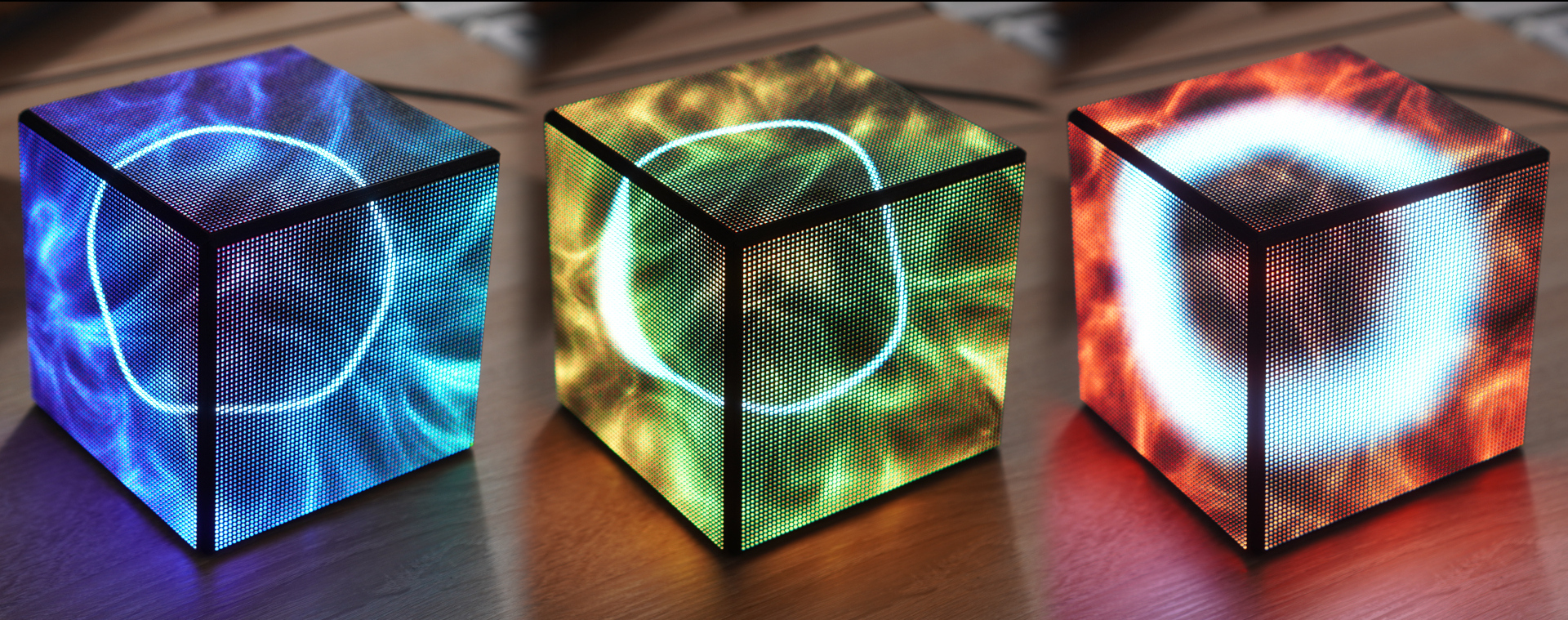
The higher the load on the CPU, the higher the chip temperature and the hotter the colors of the LED panels become. The minimum load is blue and blue, the maximum is orange and red. The total number of LEDs involved reaches 12,000. Under the cut is a description of the project, its elements, plus the source code of the software that ensures the operation of the gadget.
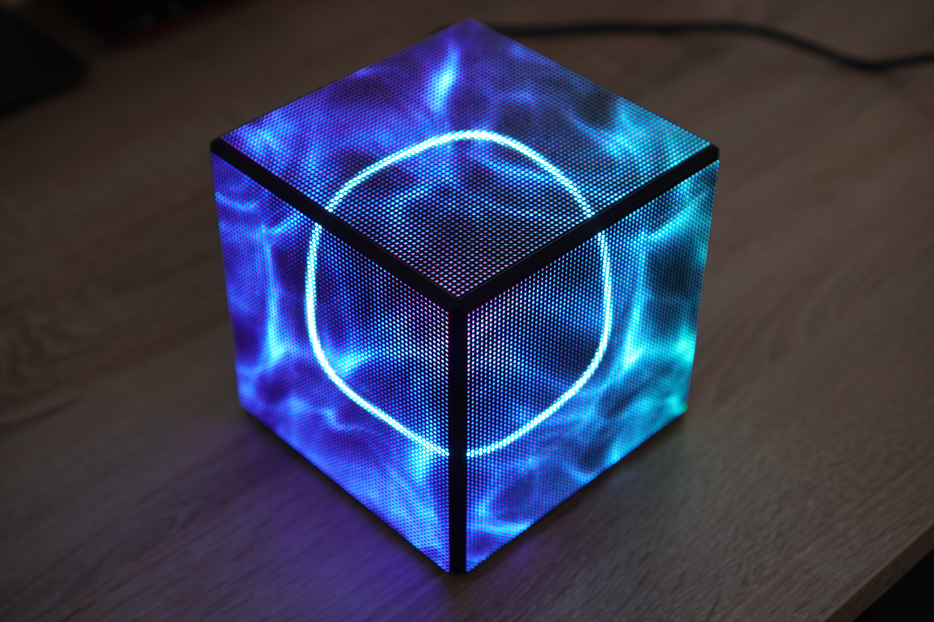
This is how it all looks:
How the idea of the project came about
Last year, the author attended the 36th Chaos Communication Congress (36C3), where he saw a huge number of DIY projects, including LED cubes. He was very impressed by this.

Most of these projects were about the device's response to external factors. So, when the device was rotated in hand, it shimmered with all the colors of the rainbow, showing colorful pictures.
Sebastian Staacks decided to develop his own project - a device that can show the load level of a PC processor. There is no particular practical sense, this is a project just for fun. The total cost of the system in the assembly was $ 150.
Project implementation
The way the LED cube looks and works is shown above. Now a few details. The device turns on automatically after booting up the PC to which it is connected.

The author says he tried to make the colors and animations as neutral as possible so as not to distract the PC user while working (or playing).
Hardware and software
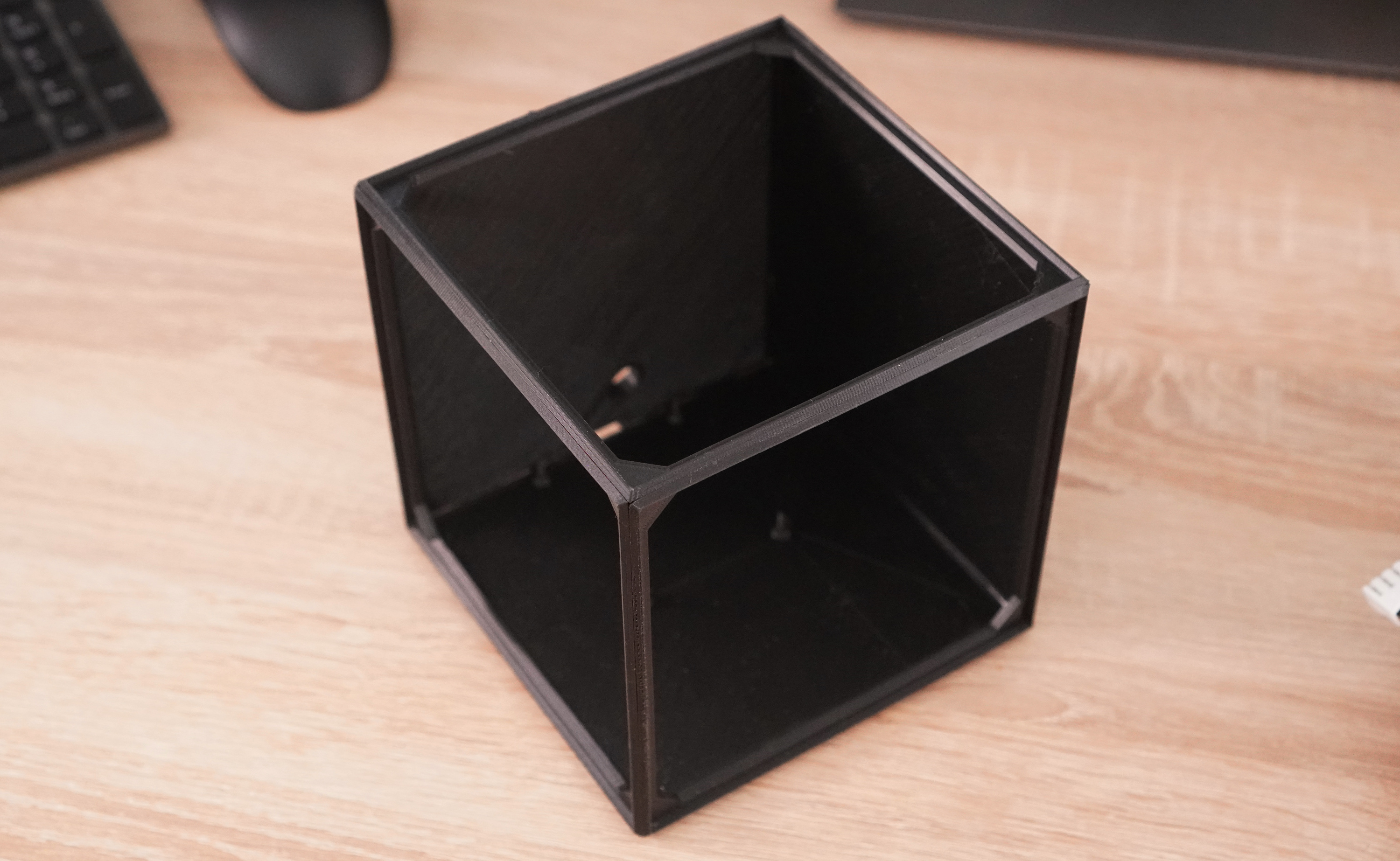
The design of the device is very simple. This is what a person who wants to disassemble the device will see.
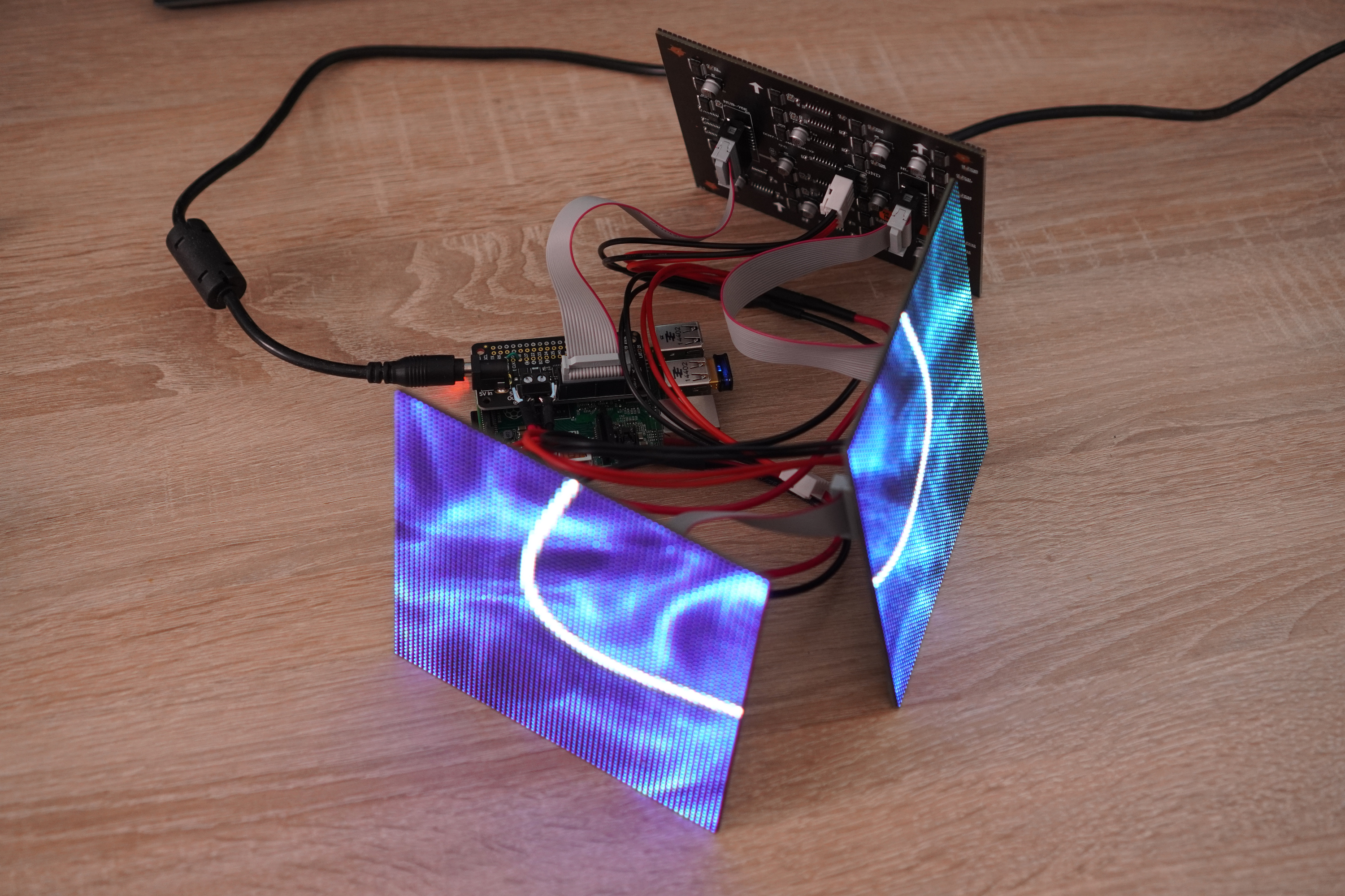
The "cube" has only three faces. This is done in order to reduce the cost and somewhat simplify the design. If all the facets worked, the project would be too expensive.
The author ordered LED panels from Aliexpress, choosing the best combination of price and quality. It was not easy, he said, as suppliers rarely provided detailed specifications for their product. Accordingly, it was not always clear if these panels were suitable for the project. As a result, the developer bought panels with 64x64 RGB LED and 5V power supply.

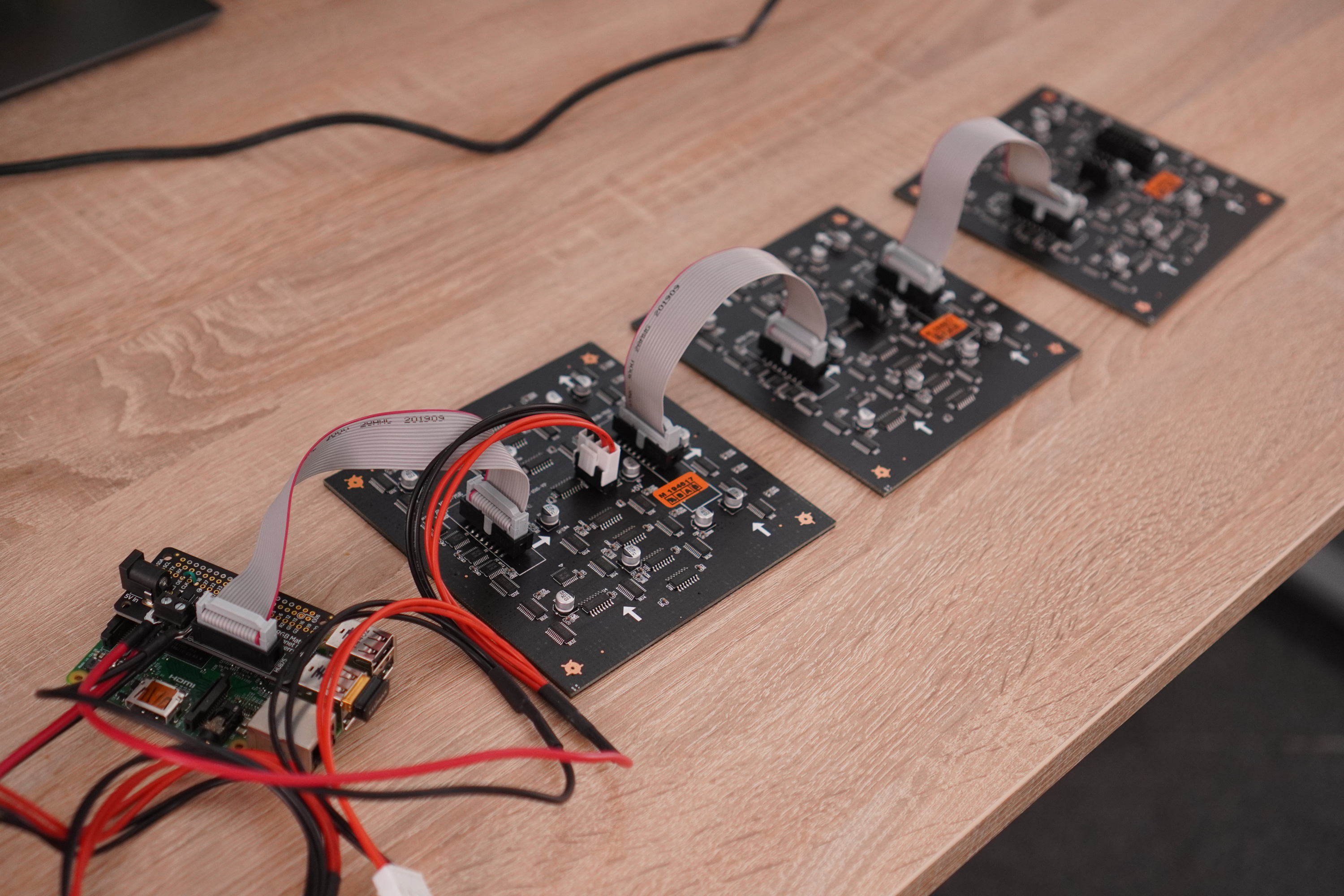
A 50W unit with 10A and 5V was used to power these panels. The adapter powers the Adafruit matrix driver, which is connected to the panels via the Raspberry Pi. The main thing is that the characteristics of the power supply cover the consumption of the system.
Panel management
As for the "raspberry", the developer used Raspberry Pi 2. At the moment, this single-board device cannot be considered too outdated morally, for such purposes it is quite enough. In addition, it almost does not heat up during operation, which cannot be said about the third and fourth generations.
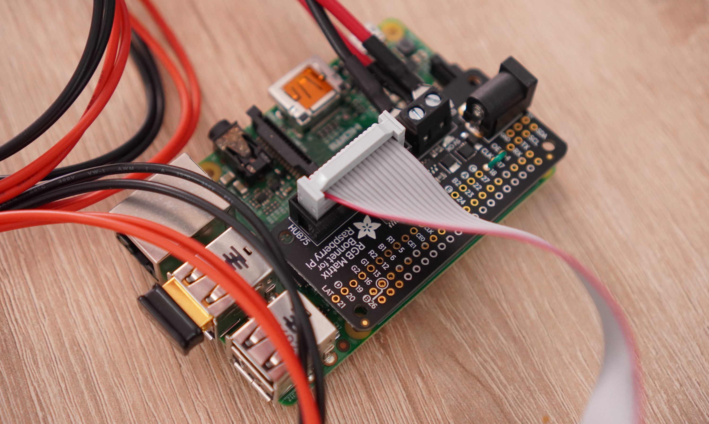
An external WiFi module was connected to the board to get rid of the cables for connecting to the network. Almost nothing was needed to solder, except for a couple of operations with the Adafruit RGB Matrix Bonnet.
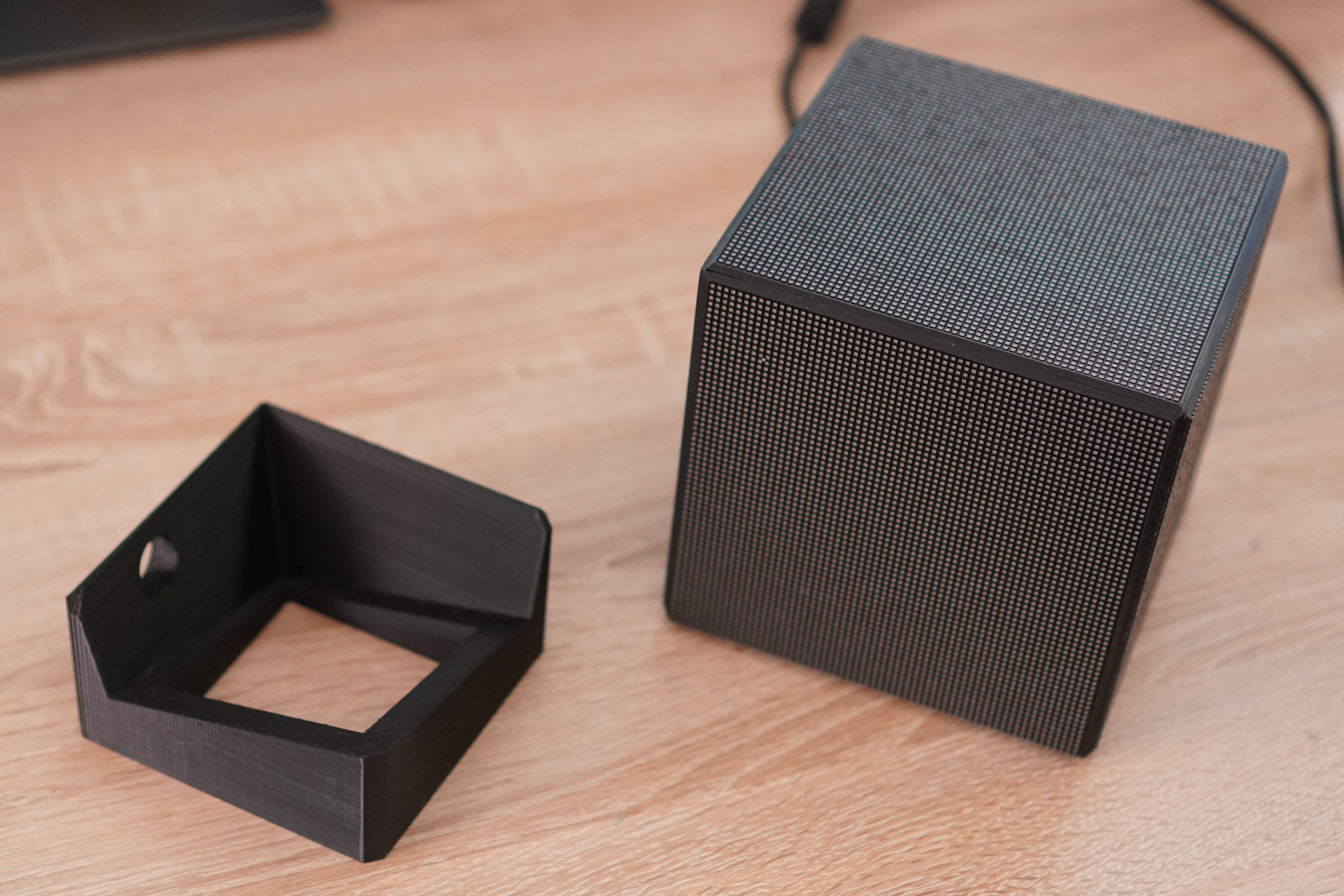
This is how the final structure looks when assembled. In order to give it all shape, the author used the case, which was printed on a 3D printer.
The panels are not glued so that they can be removed from the case at any time. Raspberry Pi mounts are also provided. You can also print the base for the cube, but in general, everything looks good and so.
Now about the software. With "hardware" everything is easier, but with the management software you will have to tinker. OpenGL shader is used for animation. In addition, a script is running on the PC that transfers the characteristics of the processor to the "malinka".
The most important piece of software is the small C ++ program that manipulates the cube. It uses the special rpi-rgb-led-matrix library . In particular, it is needed to open a UDP port to get the characteristics of the processor's work with a PC, as well as OpenGL for rendering animation. Details of the library's work can be found here .
To install, you need a script from Adafruit . Installation instructions are available at the specified link.
Here are the options to customize the panels
//LED Matrix settings
RGBMatrix::Options defaults;
rgb_matrix::RuntimeOptions runtime;
defaults.hardware_mapping = "adafruit-hat-pwm";
defaults.led_rgb_sequence = "RGB";
defaults.pwm_bits = 11;
defaults.pwm_lsb_nanoseconds = 50;
defaults.panel_type = "FM6126A";
defaults.rows = 64;
defaults.cols = 192;
defaults.chain_length = 1;
defaults.parallel = 1;
Please note that pwm_bits and pwm_lsb_nanoseconds do not look very important, but they are critical - primarily for image quality. In particular, pwm_bits defines the number of PWM bits, which defines the number of color steps. The downside of increasing this value is to decrease the refresh rate of the LED panel. You can improve the parameter by decreasing the pwm_lsb_nanoseconds settings - if your panels support such low values. If you are going to shoot a cube with a camera, it is better to increase the refresh rate so that everything looks beautiful.
It is important that the Pi is continuously running RGB Bonnet, otherwise artifacts may appear. For this, it is recommended to reserve an entire processor core.
The project can be found cpu-stats-gl.cpp, to use it in your own project. To use, you need g ++ libraries -g -o cpu-stats-gl cpu-stats-gl.cpp -std = c ++ 11 -lbrcmEGL -lbrcmGLESv2 -I / opt / vc / include -L / opt / vc / lib -Lrpi -rgb-led-matrix / lib -lrgbmatrix -lrt -lm -lpthread -lstdc ++ -Irpi-rgb-led-matrix / include /. Well, in order to add OpenGl support, you should follow the instructions from Matus Novak .
OpenGl shader
Okay, at this point the hardware is complete, plus the important code for managing the panels. In particular, you can already display text, images and GIFs. But for colorful rendering, you need to add OpenGL.
The animation that displays the processor status is implemented by a fragment shader, i.e. a small piece of code that works in parallel with "colleagues". Such areas are needed for each pixel of the panel.
To correctly project the image onto the cube, the author renders three pairs of triangles, each of which covers one face of the cube. The point is, if you are looking at a cube as a 3D object and you want to show a 2D shape such as a circle, you can assign the coordinates of an imaginary 2D canvas in front of your face to each edge of the cube.
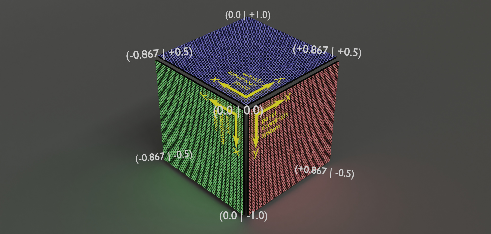
If we now "expand" the cube into a rectangular array of pixels that we are actually addressing, we can cover that array with multiple triangles. We can also map the coordinates of the "virtual canvas" to each vertex to get a mapping of our canvas coordinates to the actual pixels in the panel array.
For shaders, this is easy - you need to provide the canvas coordinates for each vertex as an additional array buffer for the GPU, allowing it to interpolate those coordinates for each pixel.
Get processor status
Information about the processor operating mode can be obtained via the UDP protocol using a Python script.
#!/usr/bin/python3
import psutil
import socket
import time

TARGET_IP="192.168.2.45"
TARGET_PORT=1234

while True:
  temperature = 0.0
  time.sleep(0.5)
  temperature += psutil.sensors_temperatures()["k10temp"][0].current
  time.sleep(0.5)
  temperature += psutil.sensors_temperatures()["k10temp"][0].current
  time.sleep(0.5)
  temperature += psutil.sensors_temperatures()["k10temp"][0].current
  time.sleep(0.5)
  temperature += psutil.sensors_temperatures()["k10temp"][0].current
  time.sleep(0.5)
  temperature += psutil.sensors_temperatures()["k10temp"][0].current
  temperature /= 5.0

  cores = psutil.cpu_percent(percpu=True)

  out = str(temperature) + "," + ",".join(map(str, sorted(cores, reverse=True)))
  socket.socket(socket.AF_INET, socket.SOCK_DGRAM).sendto(out.encode("utf-8"), (TARGET_IP, TARGET_PORT))
On the author's PC, the script starts automatically, a static IP is used for operation, reserved for the LED cube.
At this point, everything should work as intended.
Did you like this project? Perhaps you have developed something similar or, on the contrary, unique? Let us know in the comments.