1. Introduction
On the agenda was the task of developing a communication protocol for the nrf52832 microcontroller with two half-bridge Chinese strain gauges.
The task turned out to be not an easy one, since I was faced with the absence of any intelligible information. It is more likely that the "root of evil" is in the SDK itself from Nordic Semiconductor - this is constant version updates, some redundancy and confusion of functionality. I had to write everything from scratch.
I think this topic is quite relevant considering that this chip has a BLE stack and a whole set of "sweets" of the power saving mode. But I will not go deep into the technical part, since many articles have been written on this topic.
2. Description of the project
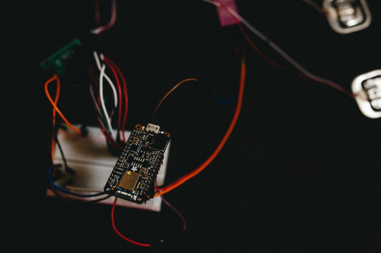
Iron:
- Adafruit Feather nRF52 Bluefruit LE (what happened to be at hand)
- ADC HX711
- Chinese strain gauges 2 pcs. (50x2 kg)
- ST-LINK V2 Programmer
Software:
- IDE VSCODE
- NRF SDK 16
- OpenOCD
- ST-LINK V2 Programmer
Everything is in one project, you only have to shaman Makefile (specify the location of your SDK).
3. Description of the code
We will use the GPIOTE module for working with peripherals based on the binding of tasks and events, as well as the PPI module for transferring data from one peripheral to another without the participation of the processor.
ret_code_t err_code;
   err_code = nrf_drv_gpiote_out_init(PD_SCK, &config);//
   nrf_drv_gpiote_out_config_t config = GPIOTE_CONFIG_OUT_TASK_TOGGLE(false);//
   err_code = nrf_drv_gpiote_out_init(PD_SCK, &config);//
We configure the PD_SCL synchronization line to the output to generate pulses with a duration of 10 μs.
   nrf_drv_gpiote_in_config_t  gpiote_config = GPIOTE_CONFIG_IN_SENSE_HITOLO(false);//
   nrf_gpio_cfg_input(DOUT, NRF_GPIO_PIN_NOPULL);//
   err_code = nrf_drv_gpiote_in_init(DOUT, &gpiote_config, gpiote_evt_handler);
static void gpiote_evt_handler(nrf_drv_gpiote_pin_t pin, nrf_gpiote_polarity_t action)
{
nrf_drv_gpiote_in_event_disable(DOUT);//
nrf_drv_timer_enable(&m_timer0);//
}
We configure the DOUT data line to read the ready state of the HX711, if there is a low level, the handler is triggered in which we disable the interrupt and start the timer to generate clock pulses at the PD_SCL output.
 err_code = nrf_drv_ppi_channel_alloc(&m_ppi_channel1);
   APP_ERROR_CHECK(err_code);
   err_code = nrf_drv_ppi_channel_assign(m_ppi_channel1,                                         nrf_drv_timer_event_address_get(&m_timer0, NRF_TIMER_EVENT_COMPARE0),                                           nrf_drv_gpiote_out_task_addr_get(PD_SCK));//
   APP_ERROR_CHECK(err_code);
   err_code = nrf_drv_ppi_channel_enable(m_ppi_channel1);//
   APP_ERROR_CHECK(err_code);
nrf_drv_gpiote_out_task_enable(PD_SCK); After that, we initialize the PPI module and switch our timer to the PD_SCL output, to generate pulses with a duration of 10 μs when the comparison event occurs, and also turn on the GPIOTE module.
nrf_drv_timer_config_t timer_cfg = NRF_DRV_TIMER_DEFAULT_CONFIG;//
   timer_cfg.frequency = NRF_TIMER_FREQ_1MHz;//    1
   ret_code_t err_code = nrf_drv_timer_init(&m_timer0, &timer_cfg, timer0_event_handler);
   APP_ERROR_CHECK(err_code);
   nrf_drv_timer_extended_compare(&m_timer0,
                                  NRF_TIMER_CC_CHANNEL0,
                                  nrf_drv_timer_us_to_ticks(&m_timer0,
                                                            10),
                                  NRF_TIMER_SHORT_COMPARE0_CLEAR_MASK,
                                  true);//
We initialize the zero timer and its handler.
  if(m_counter%2 != 0 && m_counter<=48){
       buffer <<= 1;//
        c_counter++;//
           if(nrf_gpio_pin_read(DOUT))buffer++;//
   }
The most interesting thing happens in the timer handler. The pulse period is 20 μs. We are interested in odd pulses (on the rising edge) and provided that their number is no more than 24, and there are 48 events. For each odd event, DOUT is read
, 25, 128 ( 25 ), 50 , .
 ++m_counter;//
if(m_counter==50){
      nrf_drv_timer_disable(&m_timer0);//
       m_simple_timer_state = SIMPLE_TIMER_STATE_STOPPED;//
       buffer = buffer ^ 0x800000;
       hx711_stop();//j hx711
       }
( ) HX711 .
static void repeated_timer_handler(void * p_context)
{
   nrf_drv_gpiote_out_toggle(LED_2);
   if(m_simple_timer_state == SIMPLE_TIMER_STATE_STOPPED){
      	hx711_start();//  hx711
       nrf_drv_gpiote_out_toggle(LED_1);
       m_simple_timer_state = SIMPLE_TIMER_STATE_STARTED;
   }

}
/**@brief Create timers.
*/
static void create_timers()
{
   ret_code_t err_code;

   // Create timers
   err_code = app_timer_create(&m_repeated_timer_id,
                               APP_TIMER_MODE_REPEATED,
                               repeated_timer_handler);
   APP_ERROR_CHECK(err_code);
}
RTC 10 ( ) HX711, DOUT.
, UART (baud rate 115200, TX — 6 , RX — 8 ) sdk_config.h

Thank you all for your attention, I hope this article will be useful and save valuable time for developers looking for a solution. I want to say that the technical approach that Nordic uses in its platforms is quite interesting in terms of energy efficiency.
PS
The project is still under development, so if this topic is of interest in the next article I will try to describe the algorithm for calibrating weight sensors, as well as connecting the BLE stack.