What is caustic?
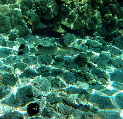
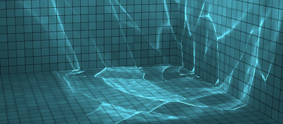
Caustics are light patterns that occur when light is refracted and reflected from a surface, in our case, at the border of water and air.
Because reflection and refraction occurs on water waves, the water acts as a dynamic lens here, creating these light patterns.

In this post, we will focus on caustics caused by light refraction, which is what normally happens underwater.
To achieve stable 60fps, we need to calculate it on a graphics card (GPU), so we will only calculate caustics with shaders written in GLSL.
To calculate it, we need:
- calculate the rays refracted on the surface of the water (in GLSL this is easy, because there is a built-in function for this )
- compute, using the intersection algorithm, the points at which these rays collide with the environment
- calculate the caustic brightness by checking the convergence points of the rays

Well known water demo on WebGL
I've always been amazed by this Evan Wallace demo showing visually realistic water caustics on WebGL: madebyevan.com/webgl-water

I recommend reading his Medium article , which explains how to compute caustics in real time using the light front mesh and GLSL PD functions . Its implementation is extremely fast and looks very nice, but has some drawbacks: it only works with a cube pool and a spherical pool ball . If you place a shark under water, the demo will not work: it is hardcoded in the shaders that there is a spherical ball under water.
He placed a sphere under the water because calculating the intersection between a refracted ray of light and a sphere is an easy task that uses very simple mathematics.
This is all good for a demo, but I wanted to create a more general solution. to compute caustics so that any unstructured meshes such as a shark can be in the pool.

Now let's move on to my technique. For this article, I will assume that you already know the basics of 3D rendering with rasterization, and that you are familiar with how a vertex shader and a fragment shader work together to render primitives (triangles) to the screen.
Working with GLSL constraints
In shaders written in GLSL (OpenGL Shading Language), we can only access a limited amount of information about the scene, for example:
- Attributes of the currently drawn vertex (position: 3D vector, normal: 3D vector, etc.). We can pass our GPU attributes, but they must be of the built-in GLSL type.
- Uniform , that is, constants for the entire currently rendered mesh in the current frame. These can be textures, camera projection matrix, lighting direction, etc. They must have a built-in type: int, float, sampler2D for textures, vec2, vec3, vec4, mat3, mat4.
However, there is no way to access the meshes present in the scene.
This is why the webgl-water demo can only be done with a simple 3D scene. It is easier to compute the intersection of a refracted ray and a very simple shape that can be represented using uniform. In the case of a sphere, it can be specified by position (3D vector) and radius (float), so this information can be passed to shaders using uniform , and calculating intersections requires very simple math, easily and quickly performed in the shader.
Some ray tracing techniques performed in shaders render meshes in textures, but in 2020 this solution is not applicable for real-time rendering on WebGL. It must be remembered that in order to get a decent result, we must calculate 60 images per second with a lot of rays. If we calculate the caustics using 256x256 = 65536 rays, then every second we have to do a significant amount of intersection calculations (which also depends on the number of meshes in the scene).
We need to find a way to represent the underwater environment in a uniform and compute the intersection while maintaining sufficient speed.
Creating an environment map
When calculating dynamic shadows is required, shadow mapping is a well-known technique . It is often used in video games, looks good, and is fast to execute.
Shadow mapping is a two-pass technique:
- First, the 3D scene is rendered in terms of the light source. This texture does not contain the colors of the fragments, but the depth of the fragments (the distance between the light source and the fragment). This texture is called a shadow map.
- The shadow map is then used when rendering the 3D scene. When drawing a fragment on the screen, we know if there is another fragment between the light source and the current fragment. If so, then we know that the current fragment is in the shadow, and we need to draw it a little darker.
You can read more about shadow mapping in this excellent OpenGL tutorial: www.opengl-tutorial.org/intermediate-tutorials/tutorial-16-shadow-mapping .
You can also watch an interactive example on ThreeJS (press T to display the shadow map in the lower left corner): threejs.org/examples/?q=shadowm#webgl_shadowmap .
In most cases, this technique works well. It can work with any unstructured mesh in the scene.
At first I thought I could use a similar approach for water caustics, that is, first render the underwater environment into a texture, and then use this texture to calculate the intersection between the rays and the environment.... Instead of rendering only the depth of the fragments, I also render the position of the fragments in the environment map.
Here is the result of creating an environment map:

Env map: the XYZ position is stored in the RGB channels, the depth in the alpha channel
How to calculate the intersection of a ray and environment
Now that I have a map of the underwater environment, I need to calculate the intersection between the refracted rays and the environment.
The algorithm works as follows:
- Stage 1: start at the intersection point between the ray of light and the surface of the water
- Stage 2: calculating refraction using the refract function
- Stage 3: go from the current position in the direction of the refracted ray, one pixel in the environment map texture.
- Step 4: Compare the registered ambience depth (stored in the current pixel of the ambience texture) with the current depth. If the depth of the environment is greater than the current depth, then we need to move on, so we apply step 3 again . If the depth of the environment is less than the current depth, it means that the ray collided with the environment at the position read from the environment texture and we found an intersection with the environment.

The current depth is less than the depth of the environment: you need to move on

The current depth is greater than the surrounding depth: we found the intersection
Caustic texture
After finding the intersection, we can compute the caustic luminance (and the caustic luminance texture) using the technique described by Evan Wallace in his article . The resulting texture looks something like this:

Caustic luminance texture (note that the caustic effect is less important on the shark because it is closer to the water's surface, which reduces the convergence of the light rays)
This texture contains information about the light intensity for each point in 3D space. When rendering the finished scene, we can read this light intensity from the caustic texture and get the following result:


An implementation of this technique can be found in the Github repository: github.com/martinRenou/threejs-caustics . Give her a star if you liked it!
If you want to see the results of the caustics calculation, you can run the demo: martinrenou.github.io/threejs-caustics .
About this intersection algorithm
This decision is highly dependent on the resolution of the environment texture . The larger the texture, the better the accuracy of the algorithm, but the longer it takes to find a solution (before finding it, you need to count and compare more pixels).
Also, reading the texture in shaders is acceptable as long as you don't do it too many times; here we create a loop that continues to read new pixels from the texture, which is not recommended.
Moreover, while loops are not allowed in WebGL.(and for good reason), so we need to implement an algorithm in a for loop that can be expanded by the compiler. This means that we need a loop termination condition known at compile time, usually the "maximum iteration" value, which forces us to stop looking for a solution if we have not found it within the maximum number of attempts. This limitation leads to incorrect caustic results if refraction is too important.
Our technique is not as fast as the simplified approach suggested by Evan Wallace, but it is much more flexible than the full-blown ray tracing approach and can also be used for real-time rendering. However, the speed still depends on some conditions - the direction of the light, the brightness of the refractions and the resolution of the ambient texture.
Closing the demo review
In this article we looked at calculating the caustic of water, but other techniques were used in the demo.
When rendering the surface of the water, we used a skybox texture and cube maps to get reflections. We also applied refraction to the surface of the water using simple refraction in screen space (see this article on reflections and refractions in screen space), this technique is physically incorrect, but visually convincing and fast. We also added chromatic aberration for more realism.
We have more ideas for further improving the methodology, including:
- Chromatic aberration on caustics: We are now applying chromatic aberration to the surface of the water, but this effect should also be visible on underwater caustics.
- Scattering of light in the volume of water.
- As Martin Gerard and Alan Wolfe advised on Twitter , we can improve performance with hierarchical environment maps (which will be used as quad trees to find intersections). They also advised to render environment maps in terms of refracted rays (assuming they are perfectly flat), which will make the performance independent of the angle of incidence of lighting.
Acknowledgments
This work on realistic, real-time water visualization was carried out at QuantStack and funded by ERDC .