Hello!
In the previous part I stopped at the fact that my rockets took off and landed successfully, and one even had an altimeter installed. In this article I will tell you how to make a simple altimeter based on the STM32 Nucleo L031K6 and a BMP 280 pressure sensor , which also stores all data in Flash memory.
Iron selection
Basic requirements for an altimeter:
- High altitude readout speed, since the rocket is at apogee not too long, and I wanted to know the maximum altitude;
- Low power consumption, so as not to put a big battery;
- Small dimensions of the entire structure.
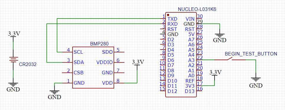
Based on them, I took STM32 Nucleo L031K6 as a microcontroller (high speed, low current consumption, small size). I decided to measure the altitude using the BMP280 barometer (the same reasons as the MK). Also added a button that, when pressed, would start recording the height. Well, all the electronics were powered by a CR2032 battery connected via an adapter. As a result, we got the following scheme:
Modules used

STM32 Nucleo L031K6
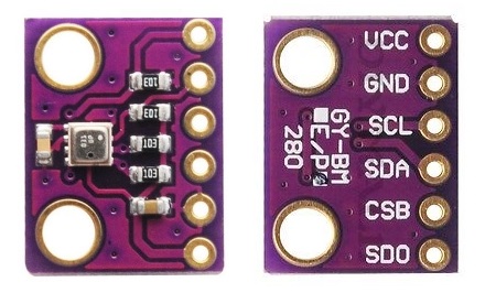
BMP280
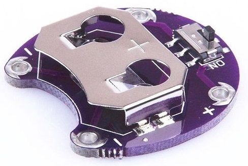
CR2032
STM32 Nucleo L031K6
BMP280
CR2032
Code development
You can find the code on my github . STM32 pins have been configured in CubeMX for IAR. To work with BMP280, I used this library , added the function of calculating the height above sea level using a barometric formula and initializing the sensor with the parameters I needed for reading frequency, filtering, etc. Since I wanted to measure the flight altitude relative to the ground, I had to first calculate the altitude above sea level in my area , take it as "zero" and measure the flight altitude relative to it. The measurement frequency was 10 Hz.
Writing to Flash memory was done as follows:
Memory organization in STM32 L031K6
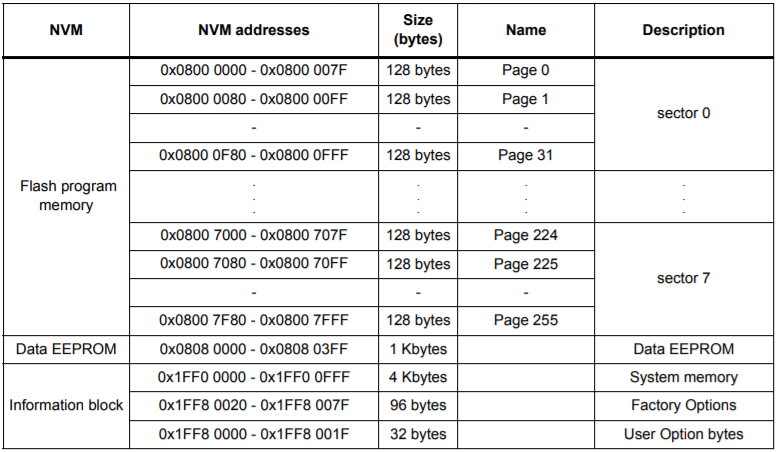
- For all measurements, I allocated 8 KB from 0x08006000 to 0x08007FFF addresses
- Allocated 2 bytes for one dimension
- I wrote down 4 bytes in Flash, that is, two measurements at once
- The maximum number of measurements - 4096, this was enough to record about 7 minutes of flight
- Recorded height in centimeters for greater accuracy
And the recording took place as follows :
- If the write iterator is even, then we store the current height in the lower half of the word into the variable with data for writing to Flash;
- If the write iterator is odd, then add the current height to the upper half of the word to the variable with data for writing to Flash and save this variable to the Flash cell
As a result, the algorithm of the program is as follows:
- After switching on, we wait for 5 seconds to press the button to start altitude measurements.
- If the button was not pressed, then we light the built-in LED and start transmitting the altitude data recorded in the Flash memory via UART
- , .
- «» Flash- .
- UART , ;
- .
When the STM was powered from the CR2032 via pin 3.3V, I found that the code does not work . The problem was that when power was applied through this leg, it was necessary to unsolder SB9 (located next to the RX and TX pins on the back of the MK), otherwise the board would constantly reboot.
Now it was necessary to check the accuracy of the altimeter. Taking a tape measure, I began to raise the altimeter to different heights and see what it measures. The test results are in the corresponding folder on the github . Text files contain raw data from STM, and Excel tables contain beautiful graphs of all tests. The accuracy corresponded to the stated - ± 10 cm. It should be remembered that I measured the height in centimetersso the numbers in the table are so large.
Assembling the altimeter
Since the rocket can hit the ground hard during landing, it was necessary to fix all the electronics well so that the wiring does not fall off when shaking, or, even worse, the modules themselves. The altimeter was placed in the head fairing (there was enough space there, and stability was increased due to the shift of the center of gravity to the head fairing) in a 3D-printed mount. STM'ka stood vertically, BMP280 with contacts up and glued an adapter for CR2032 under the mount. Due to the fact that it did not fit into the rocket body, it was necessary to grind off the minus contacts a little. Next to the contacts in the side wall of the 3D-printed mount, I made a vertical groove to pull the minus from the CR2032 through it, and under the plus I drilled a hole and put the wire through it. I thought of attaching the altimeter to the head fairing using a self-tapping screw, so there is a hole in the case,but then he abandoned this idea.
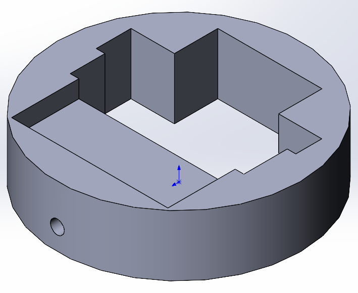
3D printed mount model
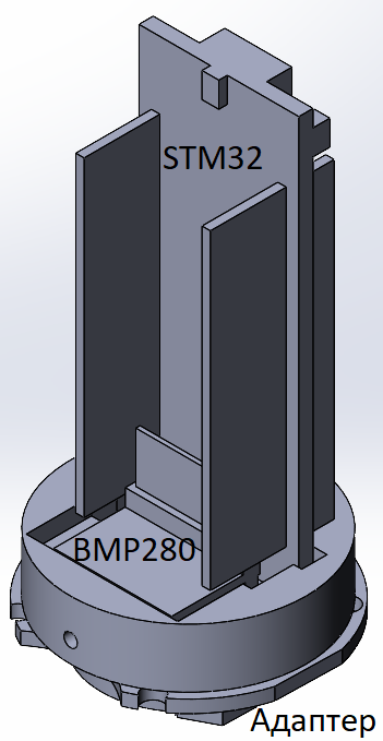
Assembled altimeter block
I glued the button next to the BMP280, installed the rest of the modules in their places, soldered all the wires and
The altimeter was tightly inserted into the rocket fairing. In order for it not to fly off anywhere after the impact, I pulled a rubber band through the hole in the mount, connecting the rocket body and the fairing.
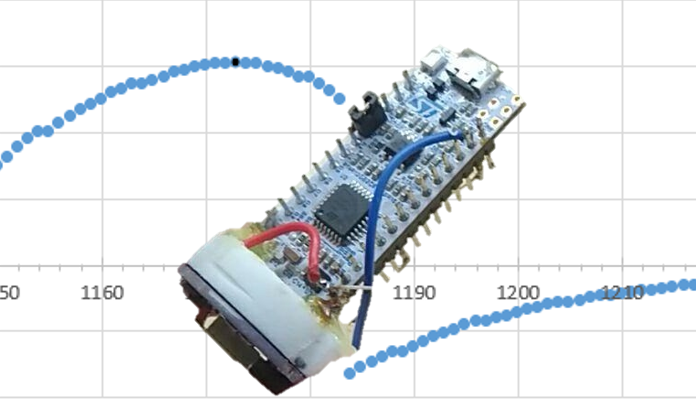
Assembled altimeter. Front

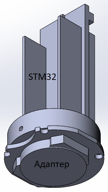
view Back view. You can see the rubber band connecting the altimeter to the rocket. The
altimeter was ready! Now I had to test it, which means that I went to the training ground again!
Altimeter Launch and Measurement Results
Unfortunately, the first start was with faulty engines, which I wrote about in the last article.
As a result, the graph turned out like this:
Horizontal - measurement number. Every 10 measurements - 1 second. Vertical - height in centimeters
The rocket took off 15m, then rushed into the ground. After passing the apogee in 1 second , some kind of anomaly began : after a value of 12m, for some reason the readings dropped to -8m. This happened at the time of the second start of the engine (which should not have been), so I do not exclude that the faulty engine somehow affected the altimeter. In all other tests, it worked fine, so this was clearly not an electronics problem. In general, those tests of the altimeter were only half successful, as an anomaly occurred in the second half of the flight. You can find the graph itself on github , it is called rocket_flight_fall_test .
After repairing the rocket, I again went to the test site and this time the tests were successful. The flight was excellent, the altimeter readings were stable and consistent with the flight. The flight schedule turned out like this:

Horizontal - measurement number. Every 10 measurements - 1 second. Vertical - height in centimeters
The rocket climbed 150m and successfully landed.Thus, this test was completely successful. I made sure that the altimeter was working and started developing new onboard equipment.
Conclusion
In the end, I completely assembled a compact altimeter that fits into a small rocket model. The tests were successful, the electronics survived takeoff and landing and measured the flight altitude. This is where I finished the project for the development of an altimeter, perhaps in the future I will use it in one of the rockets, because knowing the flight altitude is sometimes very useful (for example, if you launch rockets in order to reach a maximum or some specific altitude). Now, as I said, I am developing an on-board camera with a radio transmitter, because I do not intend to lose a rocket with such serious electronics.
Thank you for attention!