Previous articles in the series
- Development of the simplest "firmware" for FPGA, installed in Redd, and debugging using the example of a memory test
- Development of the simplest "firmware" for FPGA, installed in Redd. Part 2. Program code
- Development of your own core for embedding in an FPGA-based processor system
- Redd
- Redd
- ,
- Redd. 1:
- Redd. 2:
- :
- Redd, FTDI
- Redd
- Redd
- USB- Windows 10
- Nios II Nios II
- Redd. DMA Avalon-ST Avalon-MM
- Redd
- Redd –
- USB- Redd
- Quartus- Verilog ModelSim
Actually, this article appeared as a DOC file back in June. Then a block of five articles was written simultaneously. But uploading a DOC file to Habr is another task. Therefore, it so happened that the time for it appeared only now (and two more are languishing in anticipation). When uploading, I noticed that if you do not get into the spirit of the previous articles, this one looks kind of boring. Therefore, if there is such a desire, refresh at least the last article, or better these two ( "Making the head of a USB bus analyzer ..." and "Simulating the behavior of a Quartus project ..." ).
Introduction
So, the finished model, where can I get it? There is a project that solves exactly the same problem as the analyzer that we are developing, but has a couple of features. The first feature is for Xilinx FPGAs. Second, it is completely undocumented. It works somehow. You can even buy a ready-made breadboard, fill it with ready-made binary code ... And get some functionality. Anyone who needs a device at any cost can simply follow this path. But no one knows how to develop it. That project is here . In the \ ulpi_wrapper \ testbench directorythere is a set of files for testing the wrapper subsystem around ULPI. They recommend modeling in the Icarus Verilog environment, but I rummaged around and did not find any sensible descriptions on the surface of how to do this in the SystemC language. Therefore, I decided to continue working in the ModelSim environment. If I knew how it would end ... But I did not know. Therefore, I began research. In the course of the presentation, both successes and failures will be shown. Let's start with failures, so everyone can see how not to do it.
Unsuccessful attempt to do everything "head-on"
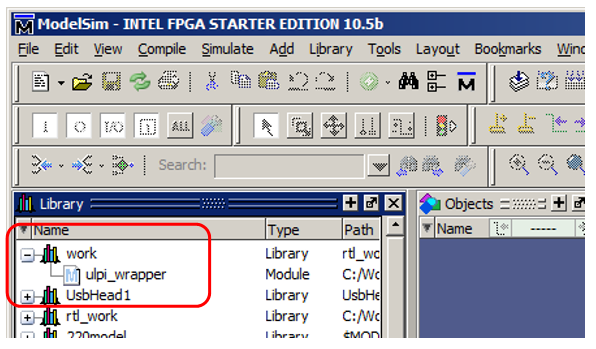
At first I decided to take a ready-made example and run it through modeling. With the usual movement of my hand (and we stuffed our hand in the last article ), I created a test suite containing files on Verilog and SystemC. It turned out something like this: I
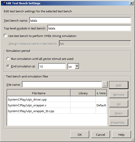
launch ModelSim and I do not see anything in the work group that would be related to SystemC. I see the Verilogo code, but the Sishny code does not.
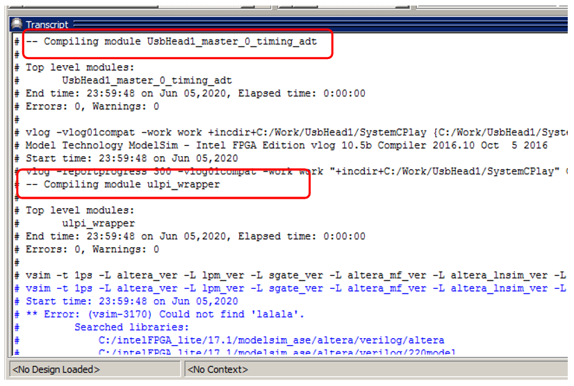
If you look at the logs, you can see that they did not try to collect it. What's the matter?
Useful information about configuring the * .do file
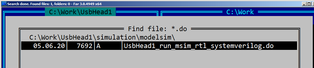
The * .do file is known to run ModelSim. But as a lover of doing everything with a "mouse", I never looked inside him. Let's look for it and open it up! There is only one such file in the project directory. This is probably what we need.
We open it. In the beginning - the assembly of all sorts of service items and files included in the project.
Watch the text
transcript on
if ![file isdirectory verilog_libs] {
	file mkdir verilog_libs
}

if ![file isdirectory vhdl_libs] {
	file mkdir vhdl_libs
}

vlib verilog_libs/altera_ver
vmap altera_ver ./verilog_libs/altera_ver
vlog -vlog01compat -work altera_ver {c:/intelfpga_lite/17.1/quartus/eda/sim_lib/altera_primitives.v}

vlib verilog_libs/lpm_ver
vmap lpm_ver ./verilog_libs/lpm_ver
vlog -vlog01compat -work lpm_ver {c:/intelfpga_lite/17.1/quartus/eda/sim_lib/220model.v}

vlib verilog_libs/sgate_ver
vmap sgate_ver ./verilog_libs/sgate_ver
vlog -vlog01compat -work sgate_ver {c:/intelfpga_lite/17.1/quartus/eda/sim_lib/sgate.v}
But at the end - obviously the assembly of the things we need, I judge this by the name of the ulpi_wrapper.v file :
vlog -vlog01compat -work work +incdir+C:/Work/UsbHead1/SystemCPlay {C:/Work/UsbHead1/SystemCPlay/ulpi_wrapper.v}

vsim -t 1ps -L altera_ver -L lpm_ver -L sgate_ver -L altera_mf_ver -L altera_lnsim_ver -L cycloneive_ver -L rtl_work -L work -L UsbHead1 -voptargs="+acc"  lalala

add wave *
view structure
view signals
run 10 us
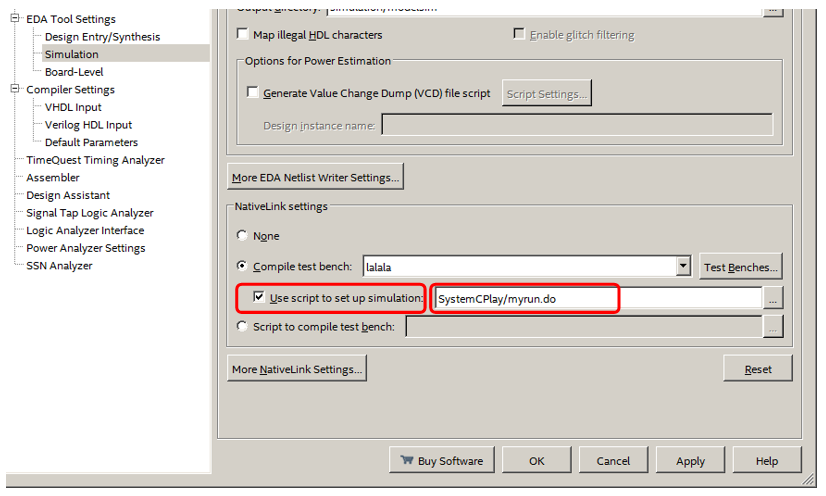
Really. There is an assembly of a Verilog module, and there is no hint of assembly of modules on SystemC. The only pity is that this DO-file is automatically created every time you start the simulation, so you can't just take it and edit it. It is created by a very complex TCL script. There is no desire to rule it. But after the article about the funny quarter , it is probably clear that such a trifle is not a reason to give up. Surely, everything is already there. The only pity is that the documentation says that "you can make the script this way, or you can do this", and there are no hints at examples. Well, let's deduce everything experimentally. Create a file C: \ Work \ UsbHead1 \ SystemCPlay \ myrun.do and try to transfer control to it. First, we try to do it like this:
The main DO file still continues to be generated, but its ending becomes like this:
vlog -sv -work UsbHead1 +incdir+C:/Work/UsbHead1/UsbHead1/synthesis/submodules {C:/Work/UsbHead1/UsbHead1/synthesis/submodules/UsbHead1_master_0_b2p_adapter.sv}
vlog -sv -work UsbHead1 +incdir+C:/Work/UsbHead1/UsbHead1/synthesis/submodules {C:/Work/UsbHead1/UsbHead1/synthesis/submodules/UsbHead1_master_0_timing_adt.sv}

vlog -vlog01compat -work work +incdir+C:/Work/UsbHead1/SystemCPlay {C:/Work/UsbHead1/SystemCPlay/ulpi_wrapper.v}

vsim -t 1ps -L altera_ver -L lpm_ver -L sgate_ver -L altera_mf_ver -L altera_lnsim_ver -L cycloneive_ver -L rtl_work -L work -L UsbHead1 -voptargs="+acc"  lalala

do C:/Work/UsbHead1/SystemCPlay/myrun.do
We see that the Verilog file is still compiled, then the modeling process is still started (although I saw this during test runs, but now I can say for sure that the vsim command starts this process), after which control is transferred to our script. This script should control the display process. But we still cannot manage the assembly. If the collected files are not enough, the system will fall off by mistake before we are allowed to do anything. Well, great, let's try the last setting.
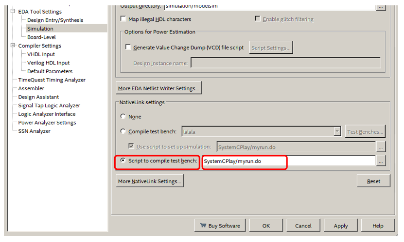
And here the fun begins. It's so important that I'll frame it.
I select a script, but it is not selected. I go into the settings (I have the previous selected option). I choose, not chosen. And so - even to blue in the face. Until I noticed it, until I found how to win - I killed the evening! It turned out that if you just select a file, the Apply button will remain gray. And the changes will not be remembered. It is imperative to make the Apply button turn black through editing other dialog parameters! In the picture above, it is exactly black. If it remains grayed out, the changes will not be saved and everything will not be reconfigured to use the script.
The script is still being formed, but its ending has become more convenient for us.
vlog -sv -work UsbHead1 +incdir+C:/Work/UsbHead1/UsbHead1/synthesis/submodules {C:/Work/UsbHead1/UsbHead1/synthesis/submodules/UsbHead1_master_0_timing_adt.sv}

do "C:/Work/UsbHead1/SystemCPlay/myrun.do"
Finally, the process of building sources for the project is completely at our mercy! Wonderful! At that time, I could only find the SystemC Verification with ModelSim document written for Xilinx. But ModelSim is in Africa ModelSim. Using the examples from this document and the samples of the DO file created in past experiments, I made the following script text (do not be alarmed by the abundance of keys, below we will throw out almost everything, we will also replace absolute paths with relative ones later, at this stage I just pulled everything from the examples and automatically generated samples).
vlog -vlog01compat -work work +incdir+C:/Work/UsbHead1/SystemCPlay {C:/Work/UsbHead1/SystemCPlay/ulpi_wrapper.v}

vlib sc_work
sccom –g –I C:/intelFPGA_lite/17.1/quartus/cusp/systemc/include –work sc_work C:/Work/UsbHead1/SystemCPlay/ulpi_driver.cpp
Drum roll ... And ModelSim declares to us:
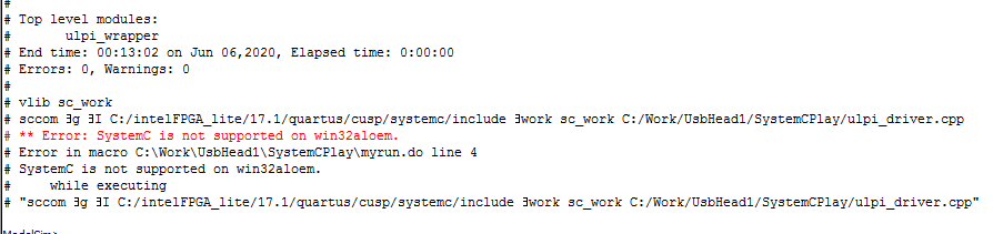
If we omit all obscene words, then I have nothing to say ... But such a path has been passed! And where can I get another ULPI model? Of course, I agreed with foreign friends who are professionally involved in serious projects for FPGAs. Especially for me, they opened remote access to a machine with a licensed ModelSim for the weekend. The second pancake also turned out to be lumpy: the 64-bit version, even in the licensed form, does not work with SystemC. But in the end, I was able to play around with the 32-bit version of the licensed ModelSim. Therefore, we continue the story ...
A few words about documentation
So. Now that I have access to the licensed software, it's time to talk about where to look for information and where to get inspiration. On the web, information about the language is rather sketchy. But in the delivery of the system, there are the following useful directories:
C: \ modeltech_10.2c \ docs \ pdfdocs - documentation, including files in PDF format. I liked the files modelsim_se_ref.pdf (ModelSim SE Command Reference Manual), modelsim_se_user.pdf (ModelSim SE User's Manual), and modelsim_se_tut.pdf (ModelSim SE Tutorial). There is not much about the language itself, but about how to connect files and how to solve dialect problems - quite.
Next, useful directory C: \ modeltech_10.2c \ examples... There are examples of ready-made * .do files and ready-made cpp and h files. The most useful example for us is C: \ modeltech_10.2c \ examples \ systemc \ vlog_sc . It shows you how to access SystemC code from Verilog code. We, in the end, will go exactly this way.
The C: \ modeltech_10.2c \ include \ systemc directory contains the source code for the language type library. Not a bad reference book. As they say, there is fish for fishlessness and cancer.
Everything from catalogs. Now the title of a wonderful book, from which you can learn a lot both about the language and about the methods of programming in it. SystemC - From the Ground Up, Second Edition. By David C. Black, Jack Donovan, Bill Bunton, Anna Keist.
SystemC dialects
So. Having gained access to the working system, I joyfully assembled the project, according to the previously created script. He assembled without mistakes! The first model from GitHub agreed to work with us! Wanting to run the benchmark, I added the ulpi_wrapper_tb.cpp file from the same directory to the project and got tons of errors. Let's say there is an error in the line:
m_vpi_handle = vpi_handle_by_name ((const char *) name, NULL);
difficult to fix, but still possible. But the line
        // Update systemC TB
        if(sc_pending_activity())
            sc_start((int)(time_value-m_last_time),SC_NS);
conjured up bad thoughts. There is no sc_pending_activity () function in the libraries. There is a sc_pending_activity_at_current_time () function , but I didn't even bother to deal with it. Instead of a thousand words of explanation, I will give a dump:
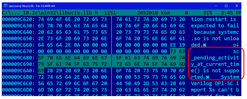
And there were 44 files with this text (* .exe, * .dll, etc.).
You could try to rewrite everything ... But is it necessary? Let me remind you that I actually started all this, because I wanted to use everything that was ready. I can develop everything in a free environment on a pure SystemVerilog, if I really spend a lot of time ... I came here so as not to waste time, but to save! But actually ... The main thing is not to forget what we are doing. We want to use the ULPI bus model. She gathered herself. Problems arose when trying to build a complete test system from the example ... Why is this? Well, the complete system does not work, and okay. We will master one model, without looking at the work of the system, by trial and error.
Eliminating dialect-based misunderstandings
So. We will be doing a mixed system. The module with the model will be written in the SystemC language, and I will submit test actions to it and the module being developed in the Verilog language. That is, you need to make the ulpi_driver module appear in the work group .
Examining the example * .do files from ModelSim's delivery, I greatly simplified the script, and in the end, I made this:
vlog +../../SystemCPlay {../../MyCores/ULPIhead.sv}

sccom -g ../../SystemCPlay/ulpi_driver.cpp
sccom -link
There are no errors, but the module did not appear in the group either. Examining the example files (remember, the best example that implements exactly this mixing of languages is in the C: \ modeltech_10.2c \ examples \ systemc \ vlog_sc directory ), I realized that the following line should be added to the end of the ulpi_driver.cpp file :
SC_MODULE_EXPORT(ulpi_driver);
The documentation for ModelSim says that these are dialect features. And voila! Here it is, our module:
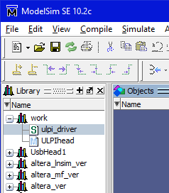
True, the Create Wave menu (we discussed this menu in the last article ) is not available for it. And he has no ports. Historically, I first dealt with ports, but methodically - I will postpone the story about them for later. Otherwise, you have to edit the code twice. To avoid this, let's first do a little preparation.
Making a clock generator
It turned out that the model has a couple of differences from the real ULPI. The first difference is that the 66 MHz clock must be generated by the chip. What do we see in the model?
sc_in<bool> clk_i;
Disorder! Let's start the rework! All work, unless otherwise indicated, is carried out in the ulpi_driver.h file.
Change the port type. It was:
sc_in<bool> clk_i;
became (I also changed the port name):
sc_inout<bool> clk;
I learned from the book that a real generator is inserted by adding a variable:
sc_clock oscillator;
We set the parameters in the constructor. As a result, the constructor takes the form:
    //-------------------------------------------------------------
    // Constructor
    //-------------------------------------------------------------
    SC_HAS_PROCESS(ulpi_driver);
    ulpi_driver(sc_module_name name): sc_module(name),
                                      m_tx_fifo(1024),
                                      m_rx_fifo(1024),
                                      oscillator ("clk66",sc_time(15,SC_NS))
    {
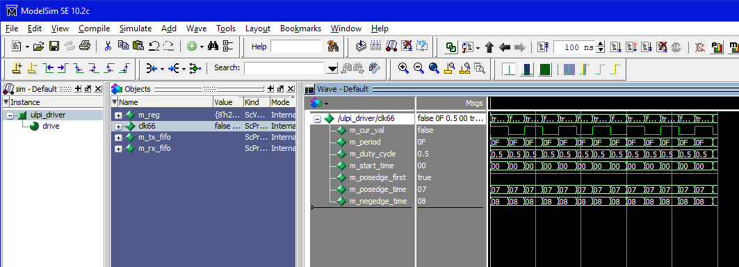
The last line is just for this. If you wish, you can even start the simulation, double-click on the usb_driver module , then pull clk66 to the temporary hut and run the simulation process a little. We already see how the generator works:
Let's not forget to change the name of the clock signal in the place where the main thread starts. It was:
SC_CTHREAD(drive, clk_i.pos());
Became:
SC_CTHREAD(drive, clk.pos());
Internal links have been replaced. But how beautiful it is to bring the signal outside, I did not find. Perhaps I just lack qualifications. But one way or another, and all attempts to pull the port out, have not been crowned with success. There was always something in the way. I even found a discussion on one forum where the author needed to do the same. The team decided that it can only be forwarded to the input ports. But we need to get out! Therefore, we do this.
Add a stream function below the constructor:
    void clkThread(void)
    {
       while (true)
       {
           wait(oscillator.posedge_event());
           clk.write (true);
           wait(oscillator.negedge_event());
           clk.write (false);
       }
    }
And add a link to it in the class constructor:
SC_THREAD(clkThread);
Let me show the current constructor area to give a holistic view of the current result:
    SC_HAS_PROCESS(ulpi_driver);
    ulpi_driver(sc_module_name name): sc_module(name),
                                      m_tx_fifo(1024),
                                      m_rx_fifo(1024),
                                      oscillator ("clk66",sc_time(15,SC_NS))
    {
        SC_CTHREAD(drive,clk.pos());
        SC_THREAD(clkThread);

        m_reg[ULPI_REG_VIDL]    = 0x24;
        m_reg[ULPI_REG_VIDH]    = 0x04;
        m_reg[ULPI_REG_PIDL]    = 0x04;
        m_reg[ULPI_REG_PIDH]    = 0x00;
        m_reg[ULPI_REG_FUNC]    = 0x41;
        m_reg[ULPI_REG_OTG]     = 0x06;
        m_reg[ULPI_REG_SCRATCH] = 0x00;
    }

    void clkThread(void)
    {
       while (true)
       {
           wait(oscillator.posedge_event());
           clk.write (true);
           wait(oscillator.negedge_event());
           clk.write (false);
       }
    }
All. The first edit is complete.
Making a bi-directional data bus
ULPI has a bi-directional data bus. And in the model we see the following description of it:
    sc_out <sc_uint<8> >    ulpi_data_o;
    sc_in  <sc_uint<8> >    ulpi_data_i;
Disorder! First we will make a blank based on the output bus, and then we will switch everything to it. Where to begin? From the fact that the bus should be able to go into the third state, and the sc_uint <8> type works only with binary data. The sc_lv <8> type will help us . Therefore, we change the tire declaration to:
sc_inout <sc_lv<8> > ulpi_data_o;
Now go to the ulpi_driver.cpp file and look for all calls to the ulpi_data_o bus there . Intuitively, I realized that there was only one place to fix:

The same text.
void ulpi_driver::drive_input(void)
{
    // Turnaround
    ulpi_dir_o.write(false);
    ulpi_nxt_o.write(false);
    ulpi_data_o.write(0x00);

    wait(oscillator.posedge_event());
}
Change the selected line to
ulpi_data_o.write("ZZZZZZZZ");
All. Now you can instead of two lines:
    sc_inout <sc_lv<8> >    ulpi_data_o;
    sc_in  <sc_uint<8> >    ulpi_data_i;
write one:
sc_inout <sc_lv<8> > ulpi_data;
and replace all references to old variables both in the h-nick and in the cpp-shnik with references to the ulpi_data variable .
Add port aliases
So. After a long search, I came to the conclusion (possibly erroneous) that in the ModelSim environment it is easy to take and see the ports for a separate module on SystemC using the GUI, no luck. However, if this module is inserted into the test system, they will appear. But while rummaging around with the theory, I found how to beautifully set aliases for port names. The final class constructor now looks like this:
    SC_HAS_PROCESS(ulpi_driver);
    ulpi_driver(sc_module_name name): sc_module(name),
                                      m_tx_fifo(1024),
                                      m_rx_fifo(1024),
                                      oscillator ("clk66",sc_time(15,SC_NS)),
                                      rst_i ("rst"),
                                      ulpi_data ("data"),
                                      ulpi_dir_o ("dir"),
                                      ulpi_nxt_o ("nxt"),
                                      ulpi_stp_i ("stp")
    {
        SC_CTHREAD(drive,clk.pos());
        SC_THREAD(clkThread);

        m_reg[ULPI_REG_VIDL]    = 0x24;
        m_reg[ULPI_REG_VIDH]    = 0x04;
        m_reg[ULPI_REG_PIDL]    = 0x04;
        m_reg[ULPI_REG_PIDH]    = 0x00;
        m_reg[ULPI_REG_FUNC]    = 0x41;
        m_reg[ULPI_REG_OTG]     = 0x06;
        m_reg[ULPI_REG_SCRATCH] = 0x00;
    }
Making a test system
Well then. I didn't succeed in doing everything automatically so that two debugged modules (the analyzer head and the ULPI bus model) jump into the test file themselves. But let's make at least a head test, and then add ULPI to it. Using the technique from the last article , I made a test system for the ULPIhead.sv file . I have a file called sim1.v and immediately renamed it sim1.sv .
Then I added the ulpi_driver module with the handles . The final script myrun.do looks like this:
vlog +../../SystemCPlay {../../MyCores/ULPIhead.sv}

sccom -g ../../SystemCPlay/ulpi_driver.cpp
sccom -link

vlog +../../SystemCPlay {../../SystemCPlay/sim1.sv}
vsim -voptargs="+acc" sim1
The last line is tortured. Without it, the Verilog code had no ports. By changing the optimization parameters, we eliminate this problem. I saw it in that * .do file, which was created to simulate our system at the very beginning, when everything was still done on the machine. True, there is a long line. I just found the key that solves the problem and copied it. And so - I do not like long lines, I threw out everything unnecessary.
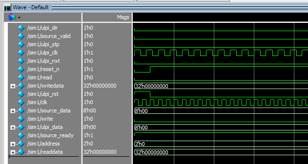
Now we add the ULPI block to the test system and make a dummy test. Just to make sure all clock signals are ticking and the buses are set to the correct values.
I got this test.
Watch the text.
`timescale 1ns / 1ns
module sim1  ;

  reg    ulpi_dir   ;
  wire   source_valid   ;
  wire    ulpi_stp   ;
  reg    ulpi_clk   ;
  reg    ulpi_nxt   ;
  reg    reset_n   ;
  reg    read   ;
  reg  [31:0]  writedata   ;
  wire    ulpi_rst   ;
  reg    clk   ;
  wire  [7:0]  source_data   ;
  reg    write   ;
  wire  [7:0]  ulpi_data   ;
  reg    source_ready   ;
  reg  [1:0]  address   ;
  wire  [31:0]  readdata   ;

  always
  begin
     clk = 1;
     #5;
     clk = 0;
     #5;
  end

  ULPIhead  DUT
  (
      .ulpi_dir (ulpi_dir ) ,
      .source_valid (source_valid ) ,
      .ulpi_stp (ulpi_stp ) ,
      .ulpi_clk (ulpi_clk ) ,
      .ulpi_nxt (ulpi_nxt ) ,
      .reset_n (reset_n ) ,
      .read (read ) ,
      .writedata (writedata ) ,
      .ulpi_rst (ulpi_rst ) ,
      .clk (clk ) ,
      .source_data (source_data ) ,
      .write (write ) ,
      .ulpi_data (ulpi_data ) ,
      .source_ready (source_ready ) ,
      .address (address ) ,
      .readdata (readdata ) );


  ulpi_driver ULPI
  (
      .clk (ulpi_clk),
      .rst (ulpi_rst),
      .data (ulpi_data),
      .dir (ulpi_dir),
      .nxt (ulpi_nxt),
      .stp (ulpi_stp)

  );

  initial
  begin
     reset_n  = 1'b0;
     source_ready = 1;
     writedata = 0;
     address = 0;
     read = 0;
     write = 0;
     #20
     reset_n  = 1'b1;
  end

endmodule
Conclusion
At the very least, we have mastered modeling in the SystemC language using the ModelSim system. However, it turned out that this requires access to the licensed 32-bit version. Free version and licensed 64-bit version do not provide such an opportunity. As I understand it, everything can be done completely free of charge in the Icarus Verilog system, but I didn't figure out exactly how to achieve this. It turned out to be easier for me to access the required ModelSim. In the next article, we will use this knowledge to model our head.
In the course of the work, quite complex modifications of the models were made. The resulting files can be downloaded here .