In the previous two parts, I talked about how I made a GUI, started controlling a stepper motor and organizing work with files on a USB flash drive.
Today I will write about the printing process, the output of the printed layers to the highlight screen and the remaining, not so essential things:
4. Output of the images of the layers to the highlight display.
5. Every little thing, such as controlling lighting and fans, loading and saving settings, etc.
6. Additional features for comfort and convenience.
- Part 1: 1. User interface.
- Part 2: 2. Working with the file system on a USB flash drive. 3. Stepper motor control for platform movement.
- 3: 4. . 5. , .. 6. .
4.
4.1 -
How could a microcontroller, which does not have specialized peripherals, be able to make the image on a high-resolution matrix at a speed of 74 million pixels per second (2560x1440 resolution, 20 frames per second) refreshed via the MIPI interface? Answer: using an FPGA with a 16MB SDRAM connected to it and two MIPI interface chips - SSD2828. Two microcircuits are worth because the display is logically divided into two halves, each of which is serviced by its own separate channel, so two displays in one are obtained.
The image for display is stored in one of 4 SDRAM banks, the FPGA chip is responsible for servicing the SDRAM and outputting the image from it to the SSD2828. FPGA generates vertical and horizontal synchronization signals for SSD2828 and drives
continuous stream of pixel color values over 24 lines (8R 8G 8B) into each of the SSD2828. The frame rate turns out to be about 20 Hz.
The FPGA is connected to the microcontroller with a serial interface (SPI) through which the microcontroller can transmit an image. It is transmitted in packets, each of which contains one line of the image (lines are counted along the short side of the display - 1440 pixels). In addition to this data, the packet also contains the SDRAM bank number, line number and checksum - CRC16. The FPGA receives this packet, checks the checksum, and if everything is ok, saves the data to the appropriate SDRAM area. If the CRC does not match, the FPGA exposes a signal on one of its pins, also connected to the microcontroller, according to which the microcontroller understands that the data did not arrive normally and can repeat the sending. For a complete image, the microcontroller must send 2560 such packets to the FPGA.
The image data inside the packet is represented in bit format: 1 - pixel is lit, 0 - pixel is dark. Alas, this completely excludes the possibility of organizing grayscale blurring of the edges of the printed layers - anti-aliasing. To organize this way of blurring, it is necessary to rewrite the configuration (firmware) of the FPGA, for which I am not yet ready. For too long and not very long I have been working with FPGA, I will have to practically re-master everything.
In addition to data packets, the microcontroller can also send a control command in which to indicate from which SDRAM bank to read data for output to the display and turn on / off image output.
The SSD2828 chips are also connected to the microcontroller via SPI. This is necessary in order to configure their registers when turned on, transfer them to sleep or active mode.
There are several more lines between the microcontroller and the FPGA / SSD2828 - the reset signal and the active chip select signals (Chip Select) for each of the microcircuits.
In general, this scheme of work is rather far from optimal, in my opinion. For example, it would be more logical to connect the FPGA to the microcontroller via a parallel external memory interface, data would be transferred much faster than via SPI with a frequency limit of 20 MHz (when the frequency rises, the FPGA stops receiving data normally). In addition, the reset signal is not connected to the physical Reset FPGA input, but as a normal logic signal, that is, the FPGA does not perform a hardware reset on it. And this also played a cruel joke, which will be discussed below.
I found out all this by understanding the source code of the manufacturer. I transferred the functions of working with FPGA from their source code as it is, I still did not fully understand how it all works. Fortunately, the Chinese have commented out their code enough (in Chinese) to be able to figure it out without much difficulty.
4.2 Reading layers from a print file
Ok, we have more or less figured out the output of the finished image, now I will tell you a little about how these images are extracted from files prepared for printing. The .pws, .photons, .photon, .cbddlp files are essentially a bunch of layer images. This format came, as far as I know, from the Chinese company Chitu, which came up with the idea of making boards with such a circuit (microcontroller - FPGA - SDRAM - SSD2828). Suppose you want to print a model with a height of 30 mm with each layer 0.05 mm thick. The slicer program cuts this model into layers of the specified thickness and for each of them forms its image.
Thus, 30 / 0.05 = 600 images with a resolution of 1440x2560 are obtained. These images are packed into an output file, the header with all the parameters is entered there, and such a file is already sent to the printer. Layer images are 1-bit deep and are compressed by the RLE algorithm one byte at a time, with the most significant bit indicating the color value and the seven least significant bits representing the number of repetitions. This method allows you to compress the layer image from 460 KB to about 30-50. The printer reads the compressed layer, decompresses it, and sends it line by line to the FPGA.
The manufacturer does this as follows:
- — 1, 1, 0. , (1440), .
- , 1440 (180 ).
- FPGA .
This is the three-step method used by the Chinese. As it turned out, this was done so that the image of the layer could be displayed in a reduced form on the interface display, showing the user what is being printed. This image is just formed from the byte array. Although what prevented from forming it immediately from the decoded bits is not clear. And what prevented the formation of a bitmap for transfer to FPGA in the same cycle is also unclear.
Now I use the same method, albeit optimized. To clarify what the optimization was, I need to clarify one more point. The data for the display line is not a solid array of payload. In the middle there are a few extra “non-working” pixels due to the fact that two display controllers are joined on the short side, and each of them has 24 “non-working” pixels at the edges. Thus, the actual transmitted data for one line of the image consists of 3 parts: data for the first half (first controller), intermediate "non-working" 48 pixels, data for the second half (second controller).
So, the Chinese, when forming the byte array inside the loop, checked whether the end of the first half was reached, if not, then the value was written by the * p pointer, otherwise by pointer * (p + 48) . This check for each of the 1440 values, and even the modification of the pointer for half of them, clearly did not contribute to the speed of the loop. I split this one loop into two separate ones - in the first, the first half of the array is filled, after this loop, the pointer is increased by 48 and the second loop begins for the second half of the array. In the original version, the layer was read and displayed in 1.9 seconds, this modification alone reduced the read and output time to 1.2 seconds.
Another change concerned data transfer to FPGA. In the original sources, it happens through DMA, but after the start of the transfer via DMA, the function waits for its completion and only after that it begins to decode and form a new line of the image. I removed this expectation so that the next line is generated while the data from the previous line is being transferred. This reduced the time by another 0.3 seconds, to 0.9 per layer. And this is when compiling without optimization, if you compile with full optimization, then the time decreases to about 0.53 seconds, which is already quite acceptable. Of these 0.53 seconds, it takes about 0.22 seconds to compute CRC16 and about 0.19 seconds to form a bitmap from a byte array before transmission. But the transfer of all lines to FPGA itself takes about 0.4 seconds and with this, most likely,there is nothing to do - everything here rests on the limitation of the maximum SPI frequency allowed for FPGA.
If I could write the FPGA configuration myself, I could give it the RLE decompression, and this could speed up the output of the layer by an order of magnitude, but how is it done?
And yes, I was going to write about the jamb associated with the fact that the FPGA is not reset by hardware on a reset signal from the microcontroller. So, when I already learned how to display the images of layers, I completed the printing process itself, I ran into an incomprehensible bug - once out of 5-10, printing was started with a completely illuminated display. I see in the debugger that the layers are read correctly, the data is sent to the FPGA as needed, the FPGA confirms the correctness of the CRC. That is, everything works, and instead of drawing a layer - a completely white display. Clearly either FPGA or SSD2828 are to blame. Once again I double-checked the initialization of SSD2828 - everything is fine, all registers in them are initialized with the required values, this can be seen during the control reading of values from them. Then I already reached into the board with an oscilloscope. And I found out that when such a failure occurs, the FPGA does not write any data to SDRAM. WE signal,allowing writing, stands rooted to the spot in the inactive level. And I probably would have fought with this glitch for a long time, if not for a friend who advised me to try giving the FPGA an explicit command to turn off the image output before resetting, so that at the time of reset there are guaranteed no calls from the FPGA to SDRAM. I tried it and it worked! This bug never showed itself again. In the end, we came to the conclusion that the IP-core of the SDRAM controller inside the FPGA was not implemented quite correctly, the reset and initialization of the SDRAM controller does not occur normally in all cases. Something prevents the correct reset if at this moment the data in SDRAM is accessed. Like this…who advised to try before resetting to give the FPGA an explicit command to turn off the image output, so that at the time of reset there are guaranteed no calls from the FPGA to SDRAM. I tried it and it worked! This bug never showed itself again. In the end, we came to the conclusion that the IP-core of the SDRAM controller inside the FPGA was not implemented quite correctly, the reset and initialization of the SDRAM controller does not occur normally in all cases. Something prevents the correct reset if at this moment the data in SDRAM is accessed. Like this…who advised to try before resetting to give the FPGA an explicit command to turn off the image output, so that at the time of reset there are guaranteed no calls from the FPGA to SDRAM. I tried it and it worked! This bug never showed itself again. In the end, we came to the conclusion that the IP-core of the SDRAM controller inside the FPGA is not implemented quite correctly, the reset and initialization of the SDRAM controller does not occur normally in all cases. Something prevents the correct reset if at this moment the data in SDRAM is accessed. Like this…that the IP-core of the SDRAM controller inside the FPGA is not implemented quite correctly, resetting and initializing the SDRAM controller does not work normally in all cases. Something prevents the correct reset if at this moment the data in SDRAM is accessed. Like this…that the IP-core of the SDRAM controller inside the FPGA is not implemented quite correctly, resetting and initializing the SDRAM controller does not work normally in all cases. Something interferes with the correct reset if the data in SDRAM is accessed at this moment. Like this…
4.3 User interface during file printing
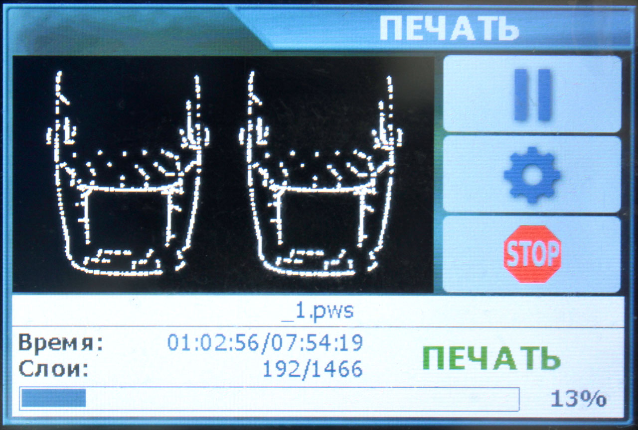
After the user has selected the file and started printing it, the following screen appears:
This is a fairly standard screen for such photopolymer printers.
The largest area of the screen is occupied by the picture of the currently exposed layer.
The display of this picture is synchronized with the backlight - when the backlight is turned on, the picture is displayed, when the backlight is turned off, the picture is erased. The picture is formed as for the UV display - along the short side of the image. I did not rush with pointers along the line offsets of this picture, but just before displaying it I give the display controller a command to change the direction of output for the data being filled in, i.e. the area of this picture turns out to be "turned" on its side.
Below is information about the progress of printing - the elapsed and estimated time of printing, the current layer and the total number of layers, a progress bar with percentages to the right of it. I also want to add the current height in millimeters after the number of layers, just to be.
On the right are the pause, settings and interrupt buttons. When you press the pause in the firmware, the pause flag is set and further behavior depends on the state of the printer at the moment. If the platform goes down for the next layer or layer exposure has already started, the firmware will complete the exposure and only after that will raise the platform to the pause height (which is set in the settings), where it will wait until the user clicks the "Continue" button:

The lifting of the platform for a pause occurs first at the speed specified in the file parameters, and after the height specified in the same parameters, the speed increases.
When printing is interrupted, a window will appear confirming this action, and only after confirmation, printing will be stopped and the platform will go up to the maximum axis height. The lifting speed, as well as during the pause, is variable - first slowly to detach the layer from the film, and then increases to the maximum.
The settings button is not functional yet, but when you click on it, the user will be taken to a screen with print parameters that can be changed - layer exposure time, height and lifting speed, etc. Right now I'm finishing it. There is also an idea to give the opportunity to save the changed parameters back to the printed file.
5. Every little thing, such as controlling lighting and fans, loading and saving settings, etc.
The board has 3 high-power MOSFET outputs - one for UV LEDs and two for fans (cooling the backlight diodes and cooling the display, for example). There is nothing interesting here - the outputs of the microcontroller are connected to the gates of these transistors and controlling them is as easy as blinking an LED. For high accuracy of the exposure time, it is switched on in the main cycle through the function setting the operating time:
UVLED_TimerOn(l_info.light_time * 1000);

void		UVLED_TimerOn(uint32_t time)
{
	uvled_timer = time;
	UVLED_On();
}
And it turns off from the millisecond interrupt of the timer when the backlighting counter reaches zero:
...
	if (uvled_timer && uvled_timer != TIMER_DISABLE)
	{
		uvled_timer--;
		if (uvled_timer == 0)
			UVLED_Off();
	}
...
5.1 Settings, loading from file and saving to EEPROM
The settings are stored in the on-board EEPROM at24c16. Here, in contrast to storing resources in a large flash memory, everything is simple - for each type of stored data, the address offset inside the EEPROM is hard-coded. In total, it stores three blocks: Z-axis settings, general system settings (language, sound, etc.) and time counters for the main printer components - illumination, display and fan.
The stored block structures contain the current firmware version and a primitive checksum - just the 16-bit sum of the values of all bytes in the block. When reading the settings from the EPROM, the CRC is checked and if it does not correspond to the real one, then the parameters of this block are assigned default values, a new CRC is calculated and the block is saved in the EPROM instead of the old one. If the read block does not match the current version, then it should be updated to the current version and it will be saved in a new form instead of the old one. This has not yet been implemented, but will be done in the future to properly update the firmware.
Some settings can be changed through the interface, but most can only be changed by loading a configuration file. Here I did not change my habits and wrote my own parser for such files.
The structure of such a file is standard: parameter name + equal sign + parameter value. One line - one parameter. Spaces and tabs at the beginning of a line and between the equal sign and the name and value are ignored. Blank lines and lines beginning with the hash character - "#" are also ignored, this character defines lines with comments. The case of letters in the names of parameters and sections does not matter.
In addition to parameters, the file also contains sections whose names are enclosed in square brackets. After the encountered section name, the parser expects that only parameters belonging to this section will go further until another section name is encountered. Honestly, I don't know why I introduced these sections. When I did this, I had some kind of thought connected with them, but now I cannot remember it.
To shorten comparisons of the read parameter name with predefined names, the first letter of the read name is parsed first, and then only those names that start with this letter are compared.
Configuration file content
# Stepper motor Z axis settings
[ZMotor]

	#    .
	#  : 0  1.  : 1.
	#         .
	invert_dir = 1

	#       .
	#  : -1  1.  : -1.
	#     -1,
	#    ,   .   1
	#      .
	home_direction = -1

	#   Z    .  ,
	#    0,   -   .
	home_pos = 0.0

	#         .
	#  :     -32000.0  32000.0.
	#  : -3.0
	#        .
	#     ,    .
	min_pos = -3.0

	#         .
	#  :     -32000.0  32000.0.
	#  : 180.0
	#        .
	#     ,    .
	max_pos = 180.0

	#   .
	#  : 0  1.  : 1.
	#         ,
	#  1,   -  0.
	min_endstop_inverting = 1

	#   .
	#  : 0  1.  : 1.
	#         ,
	#  1,   -  0.
	max_endstop_inverting = 1

	#     1   .
	steps_per_mm = 1600

	#  ,
	# , /.  : 6.0.
	homing_feedrate_fast = 6.0

	#  ,
	# , /.  : 1.0.
	homing_feedrate_slow = 1.0

	#     , /2.
	acceleration = 0.7

	#      , /.
	feedrate = 5.0

	#       (   ,
	#      ..), /2.
	travel_acceleration = 25.0

	#       (   ,
	#      ..), /.    30
	#          ,
	# 5 /.
	travel_feedrate = 25.0

	#       , .
	current_vref = 800.0

	#          , .
	current_hold_vref = 300.0

	#      ,
	#    .   .  0
	#    .
	hold_time = 30.0

	#      ,
	# .   .
	#   hold_time.  0   .
	#  ,       .
	off_time = 10.0


# General settings
[General]

	#      (0.001 )
	#      .
	#  :  0  15000.  : 700 (0.7 ).
	buzzer_msg_duration = 700

	#      (0.001 )
	#     ,   .
	#  :  0  15000.  : 70 (0.07 ).
	buzzer_touch_duration = 70

	#       180 .
	#            .
	#  : 0  1.  : 0.
	rotate_display = 0

	#           ,   .
	#    LCD-.      -
	#  .
	#  :  0  15000.  : 10.  0   .
	screensaver_time = 10
When such a file (with the .acfg extension) is selected in the list of files, the firmware will ask whether the user wants to download and apply the settings from this file and, upon confirmation, will start parsing this file.

If an error is found, a message will be displayed indicating the error type and line number. The following errors are handled:
- unknown partition name
- unknown parameter name
- invalid parameter value - when, for example, a numeric parameter is attempted to be assigned a text value
If anyone is interested - here is a complete sheet of the three main functions of the parser
void			_cfg_GetParamName(char *src, char *dest, uint16_t maxlen)
{
	if (src == NULL || dest == NULL)
		return;

	char *string = src;
	// skip spaces
	while (*string != 0 && maxlen > 0 && (*string == ' ' || *string == '\t' || *string == '\r'))
	{
		string++;
		maxlen--;
	}
	// until first space symbol
	while (maxlen > 0 && *string != 0 && *string != ' ' && *string != '\t' && *string != '\r' && *string != '\n' && *string != '=')
	{
		*dest = *string;
		dest++;
		string++;
		maxlen--;
	}

	if (maxlen == 0)
		dest--;

	*dest = 0;
	return;
}
//==============================================================================


void			_cfg_GetParamValue(char *src, PARAM_VALUE *val)
{
	val->type = PARAMVAL_NONE;
	val->float_val = 0;
	val->int_val = 0;
	val->uint_val = 0;
	val->char_val = (char*)"";

	if (src == NULL)
		return;
	if (val == NULL)
		return;

	char *string = src;
	// search '='
	while (*string > 0 && *string != '=')
		string++;
	if (*string == 0)
		return;

	// skip '='
	string++;
	// skip spaces
	while (*string != 0 && (*string == ' ' || *string == '\t' || *string == '\r'))
		string++;
	if (*string == 0)
		return;

	// check param if it numeric
	if ((*string > 47 && *string < 58) || *string == '.' || (*string == '-' && (*(string+1) > 47 && *(string+1) < 58) || *(string+1) == '.'))
	{
		val->type = PARAMVAL_NUMERIC;
		val->float_val = (float)atof(string);
		val->int_val = atoi(string);
		val->uint_val = strtoul(string, NULL, 10);
	}
	else
	{
		val->type = PARAMVAL_STRING;
		val->char_val = string;
	}

	return;
}
//==============================================================================


void			CFG_LoadFromFile(void *par1, void *par2)
{
	sprintf(msg, LANG_GetString(LSTR_MSG_CFGFILE_LOADING), cfgCFileName);
	TGUI_MessageBoxWait(LANG_GetString(LSTR_WAIT), msg);

	UTF8ToUnicode_Str(cfgTFileName, cfgCFileName, sizeof(cfgTFileName)/2);
	if (f_open(&ufile, cfgTFileName, FA_OPEN_EXISTING | FA_READ) != FR_OK)
	{
		if (tguiActiveScreen == (TG_SCREEN*)&tguiMsgBox)
			tguiActiveScreen = (TG_SCREEN*)((TG_MSGBOX*)tguiActiveScreen)->prevscreen;
		TGUI_MessageBoxOk(LANG_GetString(LSTR_ERROR), LANG_GetString(LSTR_MSG_FILE_OPEN_ERROR));
		BUZZ_TimerOn(cfgConfig.buzzer_msg);
		return;
	}

	uint16_t		cnt = 0;
	uint32_t		readed = 0, totalreaded = 0;
	char			*string = msg;
	char			lexem[128];
	PARAM_VALUE		pval;
	CFGREAD_STATE	rdstate = CFGR_GENERAL;
	int16_t			numstr = 0;

	while (1)
	{
		// read one string
		cnt = 0;
		readed = 0;
		string = msg;
		while (cnt < sizeof(msg))
		{
			if (f_read(&ufile, string, 1, &readed) != FR_OK || readed == 0 || *string == '\n')
			{
				*string = 0;
				break;
			}
			cnt++;
			string++;
			totalreaded += readed;
		}
		if (cnt == sizeof(msg))
		{
			string--;
			*string = 0;
		}
		numstr++;
		string = msg;

		// trim spaces/tabs at begin and end
		strtrim(string);

		// if string is empty
		if (*string == 0)
		{
			// if end of file
			if (readed == 0)
				break;
			else
				continue;
		}

		// skip comments
		if (*string == '#')
			continue;

		// upper all letters
		strupper_utf(string);

		// get parameter name
		_cfg_GetParamName(string, lexem, sizeof(lexem));

		// check if here section name
		if (*lexem == '[')
		{
			if (strcmp(lexem, (char*)"[ZMOTOR]") == 0)
			{
				rdstate = CFGR_ZMOTOR;
				continue;
			}
			else if (strcmp(lexem, (char*)"[GENERAL]") == 0)
			{
				rdstate = CFGR_GENERAL;
				continue;
			}
			else
			{
				rdstate = CFGR_ERROR;
				string = LANG_GetString(LSTR_MSG_UNKNOWN_SECTNAME_IN_CFG);
				sprintf(msg, string, numstr);
				break;
			}
		}

		// get parameter value
		_cfg_GetParamValue(string, &pval);
		if (pval.type == PARAMVAL_NONE)
		{
			rdstate = CFGR_ERROR;
			string = LANG_GetString(LSTR_MSG_INVALID_PARAMVAL_IN_CFG);
			sprintf(msg, string, numstr);
			break;
		}

		// check and setup parameter
		switch (rdstate)
		{
			case CFGR_ZMOTOR:
				rdstate = CFGR_ERROR;
				if (*lexem == 'A')
				{
					if (strcmp(lexem, (char*)"ACCELERATION") == 0)
					{
						if (pval.type != PARAMVAL_NUMERIC)
						{
							string = LANG_GetString(LSTR_MSG_INVALID_PARAMVAL_IN_CFG);
							sprintf(msg, string, numstr);
							break;
						}
						if (pval.float_val < 0.1)
							pval.float_val = 0.1;
						cfgzMotor.acceleration = pval.float_val;
						rdstate = CFGR_ZMOTOR;
						break;
					}
				} else
				if (*lexem == 'C')
				{
					if (strcmp(lexem, (char*)"CURRENT_HOLD_VREF") == 0)
					{
						if (pval.type != PARAMVAL_NUMERIC)
						{
							string = LANG_GetString(LSTR_MSG_INVALID_PARAMVAL_IN_CFG);
							sprintf(msg, string, numstr);
							break;
						}
						if (pval.uint_val < 100)
							pval.uint_val = 100;
						if (pval.uint_val > 1000)
							pval.uint_val = 1000;
						cfgzMotor.current_hold_vref = pval.uint_val;
						rdstate = CFGR_ZMOTOR;
						break;
					}
					if (strcmp(lexem, (char*)"CURRENT_VREF") == 0)
					{
						if (pval.type != PARAMVAL_NUMERIC)
						{
							string = LANG_GetString(LSTR_MSG_INVALID_PARAMVAL_IN_CFG);
							sprintf(msg, string, numstr);
							break;
						}
						if (pval.uint_val < 100)
							pval.uint_val = 100;
						if (pval.uint_val > 1000)
							pval.uint_val = 1000;
						cfgzMotor.current_vref = pval.uint_val;
						rdstate = CFGR_ZMOTOR;
						break;
					}
				} else
				if (*lexem == 'F')
				{
					if (strcmp(lexem, (char*)"FEEDRATE") == 0)
					{
						if (pval.type != PARAMVAL_NUMERIC)
						{
							string = LANG_GetString(LSTR_MSG_INVALID_PARAMVAL_IN_CFG);
							sprintf(msg, string, numstr);
							break;
						}
						if (pval.float_val < 0.1)
							pval.float_val = 0.1;
						if (pval.float_val > 40)
							pval.float_val = 40;
						cfgzMotor.feedrate = pval.float_val;
						rdstate = CFGR_ZMOTOR;
						break;
					}
				} else
				if (*lexem == 'H')
				{
					if (strcmp(lexem, (char*)"HOLD_TIME") == 0)
					{
						if (pval.type != PARAMVAL_NUMERIC)
						{
							string = LANG_GetString(LSTR_MSG_INVALID_PARAMVAL_IN_CFG);
							sprintf(msg, string, numstr);
							break;
						}
						if (pval.uint_val == 0)
							pval.uint_val = TIMER_DISABLE;
						else if (pval.uint_val > 100000)
							pval.uint_val = 100000;
						cfgzMotor.hold_time = pval.uint_val * 1000;
						rdstate = CFGR_ZMOTOR;
						break;
					}
					if (strcmp(lexem, (char*)"HOME_DIRECTION") == 0)
					{
						if (pval.type != PARAMVAL_NUMERIC)
						{
							string = LANG_GetString(LSTR_MSG_INVALID_PARAMVAL_IN_CFG);
							sprintf(msg, string, numstr);
							break;
						}
						if (pval.int_val != -1.0 && pval.int_val != 1.0)
							pval.int_val = -1;
						cfgzMotor.home_dir = pval.int_val;
						rdstate = CFGR_ZMOTOR;
						break;
					}
					if (strcmp(lexem, (char*)"HOME_POS") == 0)
					{
						if (pval.type != PARAMVAL_NUMERIC)
						{
							string = LANG_GetString(LSTR_MSG_INVALID_PARAMVAL_IN_CFG);
							sprintf(msg, string, numstr);
							break;
						}
						cfgzMotor.home_pos = pval.float_val;
						rdstate = CFGR_ZMOTOR;
						break;
					}
					if (strcmp(lexem, (char*)"HOMING_FEEDRATE_FAST") == 0)
					{
						if (pval.type != PARAMVAL_NUMERIC)
						{
							string = LANG_GetString(LSTR_MSG_INVALID_PARAMVAL_IN_CFG);
							sprintf(msg, string, numstr);
							break;
						}
						if (pval.float_val < 0.1)
							pval.float_val = 0.1;
						if (pval.float_val > 40)
							pval.float_val = 40;
						cfgzMotor.homing_feedrate_fast = pval.float_val;
						rdstate = CFGR_ZMOTOR;
						break;
					}
					if (strcmp(lexem, (char*)"HOMING_FEEDRATE_SLOW") == 0)
					{
						if (pval.type != PARAMVAL_NUMERIC)
						{
							string = LANG_GetString(LSTR_MSG_INVALID_PARAMVAL_IN_CFG);
							sprintf(msg, string, numstr);
							break;
						}
						if (pval.float_val < 0.1)
							pval.float_val = 0.1;
						if (pval.float_val > 40)
							pval.float_val = 40;
						cfgzMotor.homing_feedrate_slow = pval.float_val;
						rdstate = CFGR_ZMOTOR;
						break;
					}
				} else
				if (*lexem == 'I')
				{
					if (strcmp(lexem, (char*)"INVERT_DIR") == 0)
					{
						if (pval.type != PARAMVAL_NUMERIC)
						{
							string = LANG_GetString(LSTR_MSG_INVALID_PARAMVAL_IN_CFG);
							sprintf(msg, string, numstr);
							break;
						}
						if (pval.int_val < 0 || pval.int_val > 1)
							pval.int_val = 1;
						cfgzMotor.invert_dir = pval.int_val;
						rdstate = CFGR_ZMOTOR;
						break;
					}
				} else
				if (*lexem == 'M')
				{
					if (strcmp(lexem, (char*)"MAX_ENDSTOP_INVERTING") == 0)
					{
						if (pval.type != PARAMVAL_NUMERIC)
						{
							string = LANG_GetString(LSTR_MSG_INVALID_PARAMVAL_IN_CFG);
							sprintf(msg, string, numstr);
							break;
						}
						if (pval.int_val < 0 || pval.int_val > 1)
							pval.int_val = 1;
						cfgzMotor.max_endstop_inverting = pval.int_val;
						rdstate = CFGR_ZMOTOR;
						break;
					}
					if (strcmp(lexem, (char*)"MAX_POS") == 0)
					{
						if (pval.type != PARAMVAL_NUMERIC)
						{
							string = LANG_GetString(LSTR_MSG_INVALID_PARAMVAL_IN_CFG);
							sprintf(msg, string, numstr);
							break;
						}
						cfgzMotor.max_pos = pval.float_val;
						rdstate = CFGR_ZMOTOR;
						break;
					}
					if (strcmp(lexem, (char*)"MIN_ENDSTOP_INVERTING") == 0)
					{
						if (pval.type != PARAMVAL_NUMERIC)
						{
							string = LANG_GetString(LSTR_MSG_INVALID_PARAMVAL_IN_CFG);
							sprintf(msg, string, numstr);
							break;
						}
						if (pval.int_val < 0 || pval.int_val > 1)
							pval.int_val = 1;
						cfgzMotor.min_endstop_inverting = pval.int_val;
						rdstate = CFGR_ZMOTOR;
						break;
					}
					if (strcmp(lexem, (char*)"MIN_POS") == 0)
					{
						if (pval.type != PARAMVAL_NUMERIC)
						{
							string = LANG_GetString(LSTR_MSG_INVALID_PARAMVAL_IN_CFG);
							sprintf(msg, string, numstr);
							break;
						}
						cfgzMotor.min_pos = pval.float_val;
						rdstate = CFGR_ZMOTOR;
						break;
					}
				} else
				if (*lexem == 'O')
				{
					if (strcmp(lexem, (char*)"OFF_TIME") == 0)
					{
						if (pval.type != PARAMVAL_NUMERIC)
						{
							string = LANG_GetString(LSTR_MSG_INVALID_PARAMVAL_IN_CFG);
							sprintf(msg, string, numstr);
							break;
						}
						if (pval.uint_val > 100000)
							pval.uint_val = 100000;
						else if (pval.uint_val < cfgzMotor.hold_time)
							pval.uint_val = cfgzMotor.hold_time + 1000;
						else if (pval.uint_val == 0)
							pval.uint_val = TIMER_DISABLE;
						cfgzMotor.off_time = pval.int_val * 60000;
						rdstate = CFGR_ZMOTOR;
						break;
					}
				} else
				if (*lexem == 'S')
				{
					if (strcmp(lexem, (char*)"STEPS_PER_MM") == 0)
					{
						if (pval.type != PARAMVAL_NUMERIC)
						{
							string = LANG_GetString(LSTR_MSG_INVALID_PARAMVAL_IN_CFG);
							sprintf(msg, string, numstr);
							break;
						}
						if (pval.uint_val < 1)
							pval.uint_val = 1;
						if (pval.uint_val > 200000)
							pval.uint_val = 200000;
						cfgzMotor.steps_per_mm = pval.uint_val;
						rdstate = CFGR_ZMOTOR;
						break;
					}
				} else
				if (*lexem == 'T')
				{
					if (strcmp(lexem, (char*)"TRAVEL_ACCELERATION") == 0)
					{
						if (pval.type != PARAMVAL_NUMERIC)
						{
							string = LANG_GetString(LSTR_MSG_INVALID_PARAMVAL_IN_CFG);
							sprintf(msg, string, numstr);
							break;
						}
						if (pval.float_val < 0.1)
							pval.float_val = 0.1;
						cfgzMotor.travel_acceleration = pval.float_val;
						rdstate = CFGR_ZMOTOR;
						break;
					}
					if (strcmp(lexem, (char*)"TRAVEL_FEEDRATE") == 0)
					{
						if (pval.type != PARAMVAL_NUMERIC)
						{
							string = LANG_GetString(LSTR_MSG_INVALID_PARAMVAL_IN_CFG);
							sprintf(msg, string, numstr);
							break;
						}
						if (pval.float_val < 0.1)
							pval.float_val = 0.1;
						cfgzMotor.travel_feedrate = pval.float_val;
						rdstate = CFGR_ZMOTOR;
						break;
					}
				}

				string = LANG_GetString(LSTR_MSG_UNKNOWN_PARAMNAME_IN_CFG);
				sprintf(msg, string, numstr);
				break;

			case CFGR_GENERAL:
				rdstate = CFGR_ERROR;
				if (*lexem == 'B')
				{
					if (strcmp(lexem, (char*)"BUZZER_MSG_DURATION") == 0)
					{
						if (pval.type != PARAMVAL_NUMERIC)
						{
							string = LANG_GetString(LSTR_MSG_INVALID_PARAMVAL_IN_CFG);
							sprintf(msg, string, numstr);
							break;
						}
						if (pval.uint_val > 15000)
							pval.uint_val = 15000;
						cfgConfig.buzzer_msg = pval.uint_val;
						rdstate = CFGR_GENERAL;
						break;
					}
					if (strcmp(lexem, (char*)"BUZZER_TOUCH_DURATION") == 0)
					{
						if (pval.type != PARAMVAL_NUMERIC)
						{
							string = LANG_GetString(LSTR_MSG_INVALID_PARAMVAL_IN_CFG);
							sprintf(msg, string, numstr);
							break;
						}
						if (pval.uint_val > 15000)
							pval.uint_val = 15000;
						cfgConfig.buzzer_touch = pval.uint_val;
						rdstate = CFGR_GENERAL;
						break;
					}
				} else
				if (*lexem == 'R')
				{
					if (strcmp(lexem, (char*)"ROTATE_DISPLAY") == 0)
					{
						if (pval.type != PARAMVAL_NUMERIC)
						{
							string = LANG_GetString(LSTR_MSG_INVALID_PARAMVAL_IN_CFG);
							sprintf(msg, string, numstr);
							break;
						}
						if (pval.uint_val > 0)
						{
							cfgConfig.display_rotate = 1;
							LCD_WriteCmd(0x0036);
							LCD_WriteRAM(0x0078);
						}
						else
						{
							cfgConfig.display_rotate = 0;
							LCD_WriteCmd(0x0036);
							LCD_WriteRAM(0x00B8);
						}
						rdstate = CFGR_GENERAL;
						break;
					}
				} else
				if (*lexem == 'S')
				{
					if (strcmp(lexem, (char*)"SCREENSAVER_TIME") == 0)
					{
						if (pval.type != PARAMVAL_NUMERIC)
						{
							string = LANG_GetString(LSTR_MSG_INVALID_PARAMVAL_IN_CFG);
							sprintf(msg, string, numstr);
							break;
						}
						if (pval.uint_val > 15000)
							cfgConfig.screensaver_time = 15000 * 60000;
						else if (pval.uint_val == 0)
							pval.uint_val = TIMER_DISABLE;
						else
							cfgConfig.screensaver_time = pval.uint_val * 60000;
						rdstate = CFGR_GENERAL;
						break;
					}
				}

				string = LANG_GetString(LSTR_MSG_UNKNOWN_PARAMNAME_IN_CFG);
				sprintf(msg, string, numstr);
				break;

		}

		if (rdstate == CFGR_ERROR)
			break;


	}
	f_close(&ufile);


	if (tguiActiveScreen == (TG_SCREEN*)&tguiMsgBox)
	{
		tguiActiveScreen = (TG_SCREEN*)((TG_MSGBOX*)tguiActiveScreen)->prevscreen;
	}

	if (rdstate == CFGR_ERROR)
	{
		TGUI_MessageBoxOk(LANG_GetString(LSTR_ERROR), msg);
		BUZZ_TimerOn(cfgConfig.buzzer_msg);
	}
	else
	{
		CFG_SaveMotor();
		CFG_SaveConfig();
		TGUI_MessageBoxOk(LANG_GetString(LSTR_COMPLETED), LANG_GetString(LSTR_MSG_CFGFILE_LOADED));
	}
}
//==============================================================================
After successful parsing of the file, the new settings are immediately applied and saved to the EPROM.
The operating hours counters for printer components are only updated in the EPROM when the file is printed or interrupted.
6. Additional features for comfort and convenience
6.1 Clock with calendar
Well, just to make it. Why waste goodness - an autonomous real-time clock built into the microcontroller, which can operate on a lithium battery when the general power is off and consume so little that the CR2032, according to calculations, should be enough for several years. Moreover, the manufacturer even provided on the board the 32 kHz quartz required for this watch. It remains only to glue the battery holder to the board and solder the wiring from it to the common minus and to the special terminal of the microcontroller, which I did at my place.
Time, day and month are displayed at the top left of the main screen:

The same real time clock is used to count the printing time and the running hours of the components. And they are also used in the screensaver, which is described below.
6.2 Locking the screen from accidental clicks during printing
This was done at the request of an acquaintance. Well, why not, it can be useful in some cases. The lock is turned on and off by long pressing (~ 2.5 sec) on the print screen header. When the lock is active, a red lock is displayed in the upper right corner. At the end of printing, the lock is automatically released.
6.3 Decrease motor current in hold mode, shutdown motor idle
Made to reduce overall heat build-up inside the printer body. The motor can be put into hold mode with reduced current after the configured no-move time. This feature, by the way, is widespread in "adult" stepper motor drivers of the TB6560 type. In addition, in the settings, you can set the time after which, in the absence of movement, the motor will be completely de-energized. But this will also lead to the fact that the zeroing of the axis, if it was carried out, will become invalid. Both of these features can be completely disabled in the same settings.
6.4 Screensaver
Like a watch - just because I can. In the absence of pressing the screen after the time specified in the settings, the screen switches to the emulation mode of a digital desktop clock:

In addition to the time, the full date with the day of the week is also displayed. The firmware exits this mode by pressing in any part of the display. Considering that the numbers are quite large, and the electricity consumption when the engine is off is less than 2 watts, a printer with such a screensaver may well serve as a room clock :) During printing, the screensaver also appears after a specified time, but with one addition - the progress of printing at the bottom of the screen:

In the settings, you can set the response time of the screensaver or disable it.
6.5 Backlight and display check

This screen can be accessed from the "Service" menu and will be useful when checking backlight diodes or UV display. At the top, one of three images is selected, which will be displayed on the UV display - frame, full illumination of the entire display, rectangles. At the bottom there are two buttons that turn on and off the backlight and display. The included light will automatically turn off after 2 minutes, usually this time is enough for any test. When you exit this screen, both the backlight and the display will be automatically turned off.
6.6 Settings

This screen is also accessible from the Tools menu. There are very few settings here and, to be honest, I never came up with which settings would be so often in demand that it would make sense to put them in the interface, and not just in the configuration file. It still will be added to reset the counters of use of the printer, well, the more I do not know :)
Of course, you can set the time and date (since there is a clock) to open a separate screen:

You can adjust the height of the platform lift on pause and turn on and off sound of display clicks and messages. When changing the settings, the new values will only take effect until the power is turned off and will not be saved to the EPROM. To save them, after changing the parameters, press the save button in the menu (with a floppy icon).
Numerical values are entered in a special screen:

Here I have implemented all the features that I lacked in other printers.
- "±" and "." Buttons work only if the edited parameter can be negative or fractional, respectively.
- If, after entering this screen, any numeric button is pressed first, the old value will be replaced by the corresponding digit. If the button is ".", It will be replaced with "0." That is, there is no need to erase the old value, you can immediately start entering a new one.
- "" button, zeroing the current value.
Pressing the Back button will not apply the new value. To apply it, you need to click "OK".
6.7 Finally - Printer Information Screen

This screen is accessible directly from the main menu. The most important thing here is the firmware / FPGA version and the operating time counters. At the bottom, there is still information about the author of the interface and the address of the repository on GitHub. The author of the interface is the foundation for the future. If I still make it possible to configure the interface through a simple text file, then there will be an opportunity to specify the author's name.
the end
This is the last part for this pet project of mine. The project lives and develops, although not as fast as I would like, but it is already quite efficient.
I probably should have put in more code ... But I don't think there are chunks in my code to brag about. In my opinion, it is more important to describe how it works and what has been done, and the code is there, it’s all on GitHub, who will be interested, I can watch it there in its entirety. I think so.
I look forward to your questions and comments, and thanks for your interest in these articles.
- Part 1: 1. User interface.
- Part 2: 2. Working with the file system on a USB-stick. 3. Stepper motor control for platform movement.
- Part 3:4. Output of images of layers to the backlight display. 5. Every little thing, such as controlling lighting and fans, loading and saving settings, etc. 6. Additional features for comfort and convenience.
Links
MKS DLP kit on Aliexpress
Original firmware sources from the manufacturer on GitHub
Schemes from the manufacturer of two versions of the board on GitHub
My sources on GitHub