
An article from the Instructables website for a homemade competition using CNC machines
As for me, the most frequently used objects in our life are watches and calendars. The passage of time has always been one of the main themes in people's lives. And I am the same - I think you can understand this by the number of my projects related to watches. Now I want to show you one of my calendar projects.
There are thousands of calendar designs, but I've always liked perpetual calendars. I've always loved the idea of a calendar that can be reused so that you don't have to change your office calendar every year. The downside to these calendars is that many of them are large, space-consuming gizmos that are difficult to read and interpret. Or there are also cubes with days of the week, or cubes with months that need to be constantly updated. There are also calendars made of pieces (wooden, metal, magnetic) with numbers from 1 to 31, which must be selected and placed on a special panel.
I settled on the option in which there are two sets of numbers of the month, and using the slider, you can select the structure of days in the current month.
Next, I'll explain step by step how it all works.


Step 1: How it works
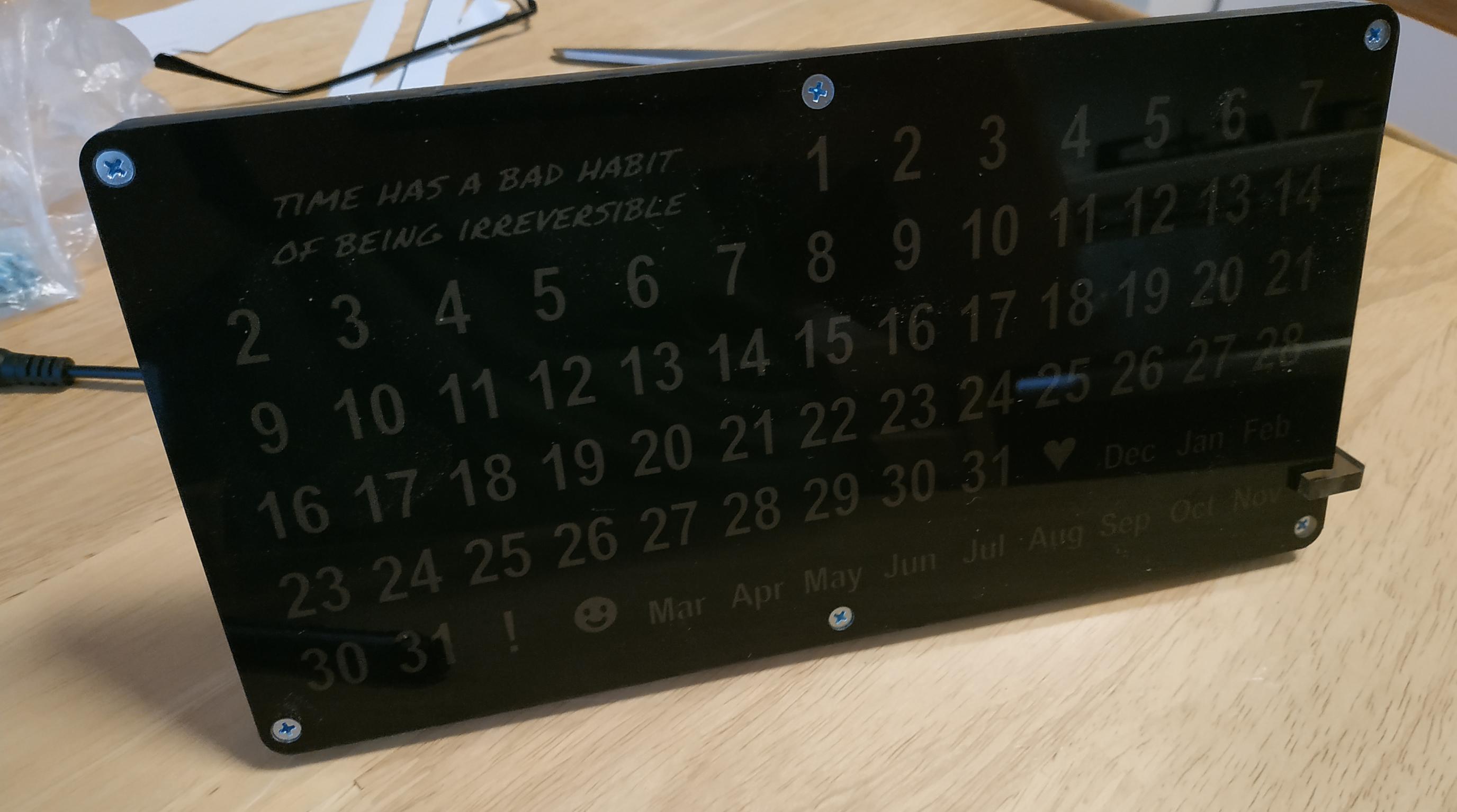
I searched for a long time on the Internet for the origin of such a perpetual calendar, but I never found it. In the pictures above, you can see what the calendar looks like. In a table of 13 columns and 6 (sometimes - 5) rows, the dates of the month are placed, and by moving the frame, you can select the configuration of the days corresponding to the current month. For October 2020, it will turn out as in the picture below:

However, with September 2020, a problem arises:

Although there are 30 days in September, the 31st number in the calendar is visible. The situation is even worse with February 2021, since it has 28 days, but the dates are 29, 30 and 31.
This is the main drawback of such a calendar - for many months the dates will reach 31. Despite this, you can find thousands of products or projects on the Internet made on this principle. Do a search on etsy , look at these links on Amazon (link1 , link2 ) and Youtube ( link1 , link2 , link3 , link4 ) and you'll understand what I mean.
Such calendars also have one more serious drawback, like all office calendars - they need to be adjusted monthly, and sometimes daily, which does not always work, because sometimes we just forget about it :)
My project takes into account all these problems. To show the dates for the current month, I use a strip of LEDs located behind a paper screen with dates printed on it. In this case, only those LEDs that should highlight the real dates of the current month will light up.
The colors can be selected, the current day is highlighted in a different color, weekends and weekdays are different in color - and all this is done using a microcontroller that receives the current date from the Internet, so the calendar is updated automatically. For example, February 2021 may look like this (the first working day there is Monday):

Step 2: What you need for this


Required components:
- 2 sheets of smoky plexiglass, 3 mm and 5 mm thick.
- 3mm countersunk head bolts, washers and nuts.
- A4 white paper.
- 72xWS2812 LEDs with 60 strips per meter.
- ESP-01 module with ESP8266.
- Stabilizer 5V / 3.3V.
- Power connector 5.5 x 2.5 mm female.
- 5 V / 2 A power supply with 5.5 x 2.5 mm male power connector.
- Connecting wires.
Tools
- CNC machine, even inexpensive, since plastic processing is needed.
- Soldering Station.
- Jet printer.
- Glue gun.
- Drill 3 mm.
- Drill 5 mm per taper.
- All sorts of common tools.
Step 3: CNC machining of the components


The most important part of the project, of course, is the processing of the four components of the calendar case. All necessary vector files are attached. The front part consists of a 3 mm sheet, the back - of a 5 mm sheet.
There are many detailed articles on the very process of cutting with a CNC machine on the Internet ( link , link , link , link , link , link , link ).
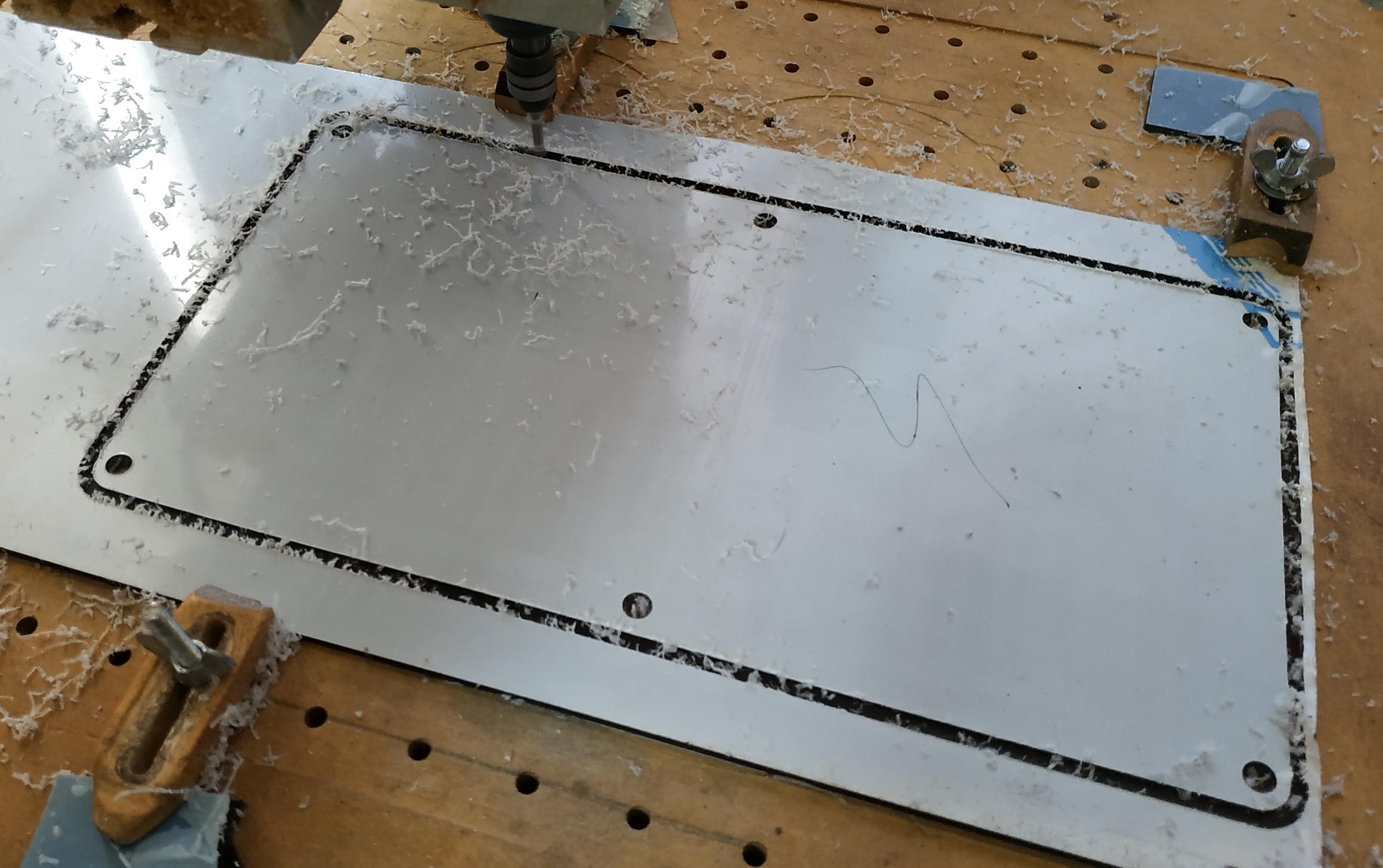
Generally speaking, the rotational speed of the drill should be low and the feed rate of the material should be high to avoid material melting. Melting will not cut the edges well and can cause vibration and even damage to the cutter. I used a 3 mm drill at 10,000 rpm and a feed rate of 420 mm / min. I used a 5 mm drill bit to make holes for the screw heads. Drilling depth - 1.5 mm. As a result, the heads fit very well. At the beginning of the section there are photos of the work process and the result.
content.instructables.com/ORIG/FIH/5PZO/KEN0JZJ6/FIH5PZOKEN0JZJ6.svg content.instructables.com/ORIG/FQE/VGPV/KEN0JZJ7/FQEVGPVKEN0JZJ7.svg
content.instructFJVKEN0JZJ7.svg
content.instructFJV8. svg
content.instructables.com/ORIG/F28/M3ON/KEN0JZJ9/F28M3ONKEN0JZJ9.svg
4:


While the machine was working on cutting the plexiglass, I started to print the screen.
Below I attach SVG files in two versions - one on a black background, the other on a white background. Also on the calendar, I put the names of the months, a logo (replace with your favorite) or a motto, and some special icons that I plan to use in the future to notify about such important events as birthdays, holidays, etc.
The prints were done on a regular inkjet, only on good quality paper, with a uniform texture, crisp white color and slightly thicker than regular paper for office printers. I printed the same drawing 5 times in a row on the same piece of paper - so that the black background was as opaque as possible. I attached some of the photos of the result at the beginning of the section.
Then I put the paper aside to dry the ink and moved on to the electronic part.
content.instructables.com/ORIG/FYA/VY88/KEN0K2O3/FYAVY88KEN0K2O3.svg
content.instructables.com/ORIG/F7V/R8IP/KEN0K2O4/F7VR8IPKEN0K2O4.svg
Step 5: electronics


The diagram is very simple, I attached it above. To implement it, I did the following:
- Cut 5 pieces of tape with 13 LEDs, and one piece with 7 LEDs. Tinned edges to facilitate soldering of all connecting wires.
- I glued the tapes into the cut-out channels on the back wall of the calendar according to the diagram (my LED strips come with an adhesive layer).
- I connected the Data Out and Data In pins of the LED strips with blue wires.
- I soldered the power supply with red wires (+ 5 V), and between the tape segments I used green wires (ground) observing the polarity.
- I soldered the wires from the tape to the stabilizer, and from it to the ESP-01.
- On ESP, I connected Vcc and CH_PD, then I connected the GPIO2 pin of the ESP-01 module and Data In from the first piece of tape.
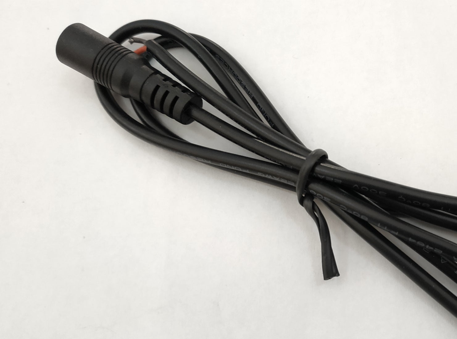
- Finally, I soldered the power wire.
Step 6: assembly


Having finished soldering the electronics, I fixed everything I could with hot glue - the ESP-01 module, stabilizer, wires. Later:
- I cut out the printed drawing with 1 cm margins. I made 2 holes in the cutout at opposite corners. I inserted the screws through the back of the case into the holes corresponding to the holes in the paper cut, and screwed the middle part of the case with the grill to this.
- Carefully threaded the screws through the holes in the paper so that the printout matches the grille and LEDs as best as possible.
- I put the front of the case on the paper.
- I inserted the remaining 4 screws, tightened them with washers and nuts.
- , , .
- .
7:


The program is made based on the same framework that I used in my project with ESP8266 - ESP 8266 Arduino IDE WebConfig and BVB_WebConfig_OTA_V7 .
The framework offers a web interface for configuring the access of the ESP8266 module to the router, as well as access to the date and time that the module receives from the NTP server. It only remained to add a function for displaying the days of the current month and the current date, but I also wanted to be able to choose whether to consider Sunday or Monday as the first day of the week. I also wanted to use other LEDs, so I thought it would be interesting to highlight special icons corresponding to important events - birthdays or holidays. The source of the program is on Github .
In my other articles, I wrote in more detail about this framework ( link , link , link , link ).
I programmed the microcontroller using an ESP-01 adapter and a USB to TTL adapter.
To compile and load the program into ESP, I used the Eclipse IDE for Arduino called Sloeber , the esp8266 library version 2.7.4, and the FastLED library version 3.3.3.
Step 8: It's Alive!
I ran tests for different dates in the future, you can watch them in the video below. I think it is quite clear from it how the calendar works.
It can be seen that my motto is seen poorly. I thought it would be fine to illuminate it with the stabilizer LED, but I guess I'll have to add a couple more LEDs specifically for it.
Step 9: Options, what's next?
I made a plexiglass calendar because I had it close at hand. Nothing prevents you from making the grille and back from other plastic or wood - only the front should be transparent or translucent.
The size may seem too large - if you want to reduce it, you can use LED strips with 120 LEDs per meter, or even two 8x8 LED arrays.
Although I did everything on a CNC machine, the same can be done using laser cutting or a 3D printer. However, in the latter case, you will need a printer capable of accommodating 235 × 120 mm parts.
Several events can be entered into the program, but it is obvious that it would be easier to make a special interface for their transmission. It would also be interesting to sync the perpetual calendar with your mobile app.