Continuation of the article about writing your own firmware for a photopolymer LCD 3D printer.
In this part, I will continue to describe the stages of my project:
2. Working with a USB flash drive and files on it
3. Controlling a stepper motor for moving the platform.
- Part 1: 1. User interface.
- Part 2: 2. Working with the file system on a USB-stick. 3. Stepper motor control for platform movement.
- Part 3: 4. Displaying images of layers on the backlight display. 5. Every little thing, such as controlling lighting and fans, loading and saving settings, etc. 6. Additional features for comfort and convenience.
2. Working with a USB flash drive and files on it
I have never worked with a USB host on microcontrollers before. As a USB device - I made firmware with both the CDC class (COM port emulation) and the HID class, but it did not work with the host. Therefore, to speed up the process, I created all the initialization of this peripheral in STM32CUBE. As a result, I got a host working in USB FS mode that supports mass storage devices. In the same cube, I immediately connected the FatFS library to work with the file system and files. Then you just had to copy the received sources into your project and figure out how to work with them. It turned out to be easy and there is not much to describe here. The usb_host.c file from Cuba has a global variable Appli_state of type ApplicationTypeDef:
typedef enum {
  APPLICATION_IDLE = 0,
  APPLICATION_START,
  APPLICATION_READY,
  APPLICATION_DISCONNECT
}ApplicationTypeDef;
At various events of the USB host peripheral (in interrupts), this variable can take one of the listed states, indicating the current state of the host. In the main loop of the program, it remains to simply track changes in this variable and react accordingly. For example, if its value has changed to APPLICATION_READY, then the flash drive or card reader is connected and successfully initialized, you can read files from them.
There are no complications with FatFS either - the Cube already completely configures it and "connects" to the USB host, so immediately after connecting the flash drive, you can access the functions of this library to work with files. True, the newly updated cube includes the old version's library. After updating its files to a fresh version, I had to fix the names of the defines from the FatFS configuration in some places in the Cuban source code, because they have changed in the new version. But the update did not bring any particular problems, everything went quickly and easily.
But for FatFS to work with Cyrillic in the names of files and directories, I had to tinker a little. In order for FatFS to correctly read Cyrillic names, it is necessary to enable Unicode in its configuration, and after that all strings associated with FatFS must be only in this encoding - disk names, file names, etc. At the same time, the text editor in the IDE and FatFS support Unicode with different positions of the high byte - one with Little Endian, the other with Big Endian, so it is impossible to simply write sources with Unicode texts. And I don't want to, to be honest. That's when I had to write converters from ANSI and UTF-8 to Unicode and vice versa, plus several functions for working with strings of different encodings in different combinations. For example, copy a UTF-8 string to a Unicode string, or append an ANSI string to a Unicode string. However, ANSI strings seem to benowhere is left, all sources are completely converted to UTF-8 encoding.
So, opening a file with a given name now looks something like this:
tstrcpy(u_tfname, UsbPath);	//    (Unicode)    (Unicode)
tstrcat_utf(u_tfname, SDIR_IMAGES);	//    (Unicode)   (UTF-8)
tstrcat_utf(u_tfname, (char*)"\\");	//    (Unicode)  (UTF-8)
tstrcat(u_tfname, fname);	//    (Unicode)   (Unicode)
When it all worked quickly, I wanted to check the speed of reading files from a flash drive. Reading a 10-megabyte file in 4 KB blocks showed a speed of about 9 Mbps, which, in general, was pretty good and suited me.
I tried to study the issue of transferring this case to DMA, but it turned out that the peripherals of the USB host simply do not have access to DMA. Well, or I didn't find it :) Therefore, it seemed logical to organize all read / write buffers for USB files in CCM (Core Coupled Memory) - a 64 KB RAM area, which also does not have a DMA output. In the same memory area, it makes sense to place other variables / arrays that do not work with DMA, just to leave more memory in regular RAM. By the way, it seemed to me that the kernel itself works with this memory a little faster than with ordinary memory.
2.1 File User Interface
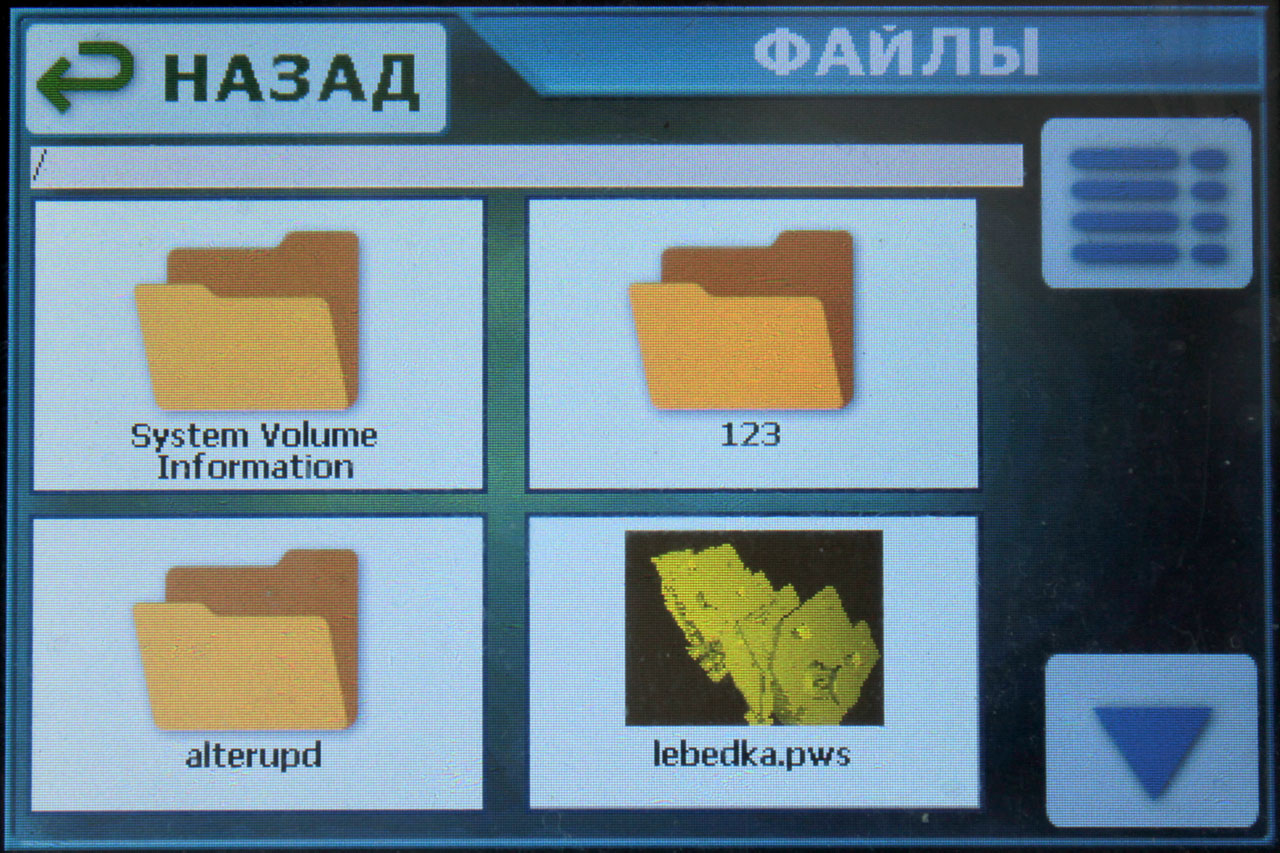
The Anycubic Photon S printer that I own displays a list of files as preview icons, 4 pieces per screen. And in principle, this is quite convenient - you can see the file name, in the preview picture you can see approximately what kind of model. Therefore, I followed the same path - files are displayed 4 pieces per page in the form of preview images with the file name.
The familiar yellow folder is drawn on the directory icons, and a gear on the settings files. Only those files for which the extension falls under one of the known ones are displayed. Currently, these are .pws files (files prepared by the slicer for printing) and .acfg files (text files with printer settings).
Since the firmware also works with directories that the user can enter, I placed a line above the list of files in which the current path is written. Buttons for leaving the current directory or scrolling down and up appear only when they make sense - that is, when you can leave the current directory or scroll down or up the list.

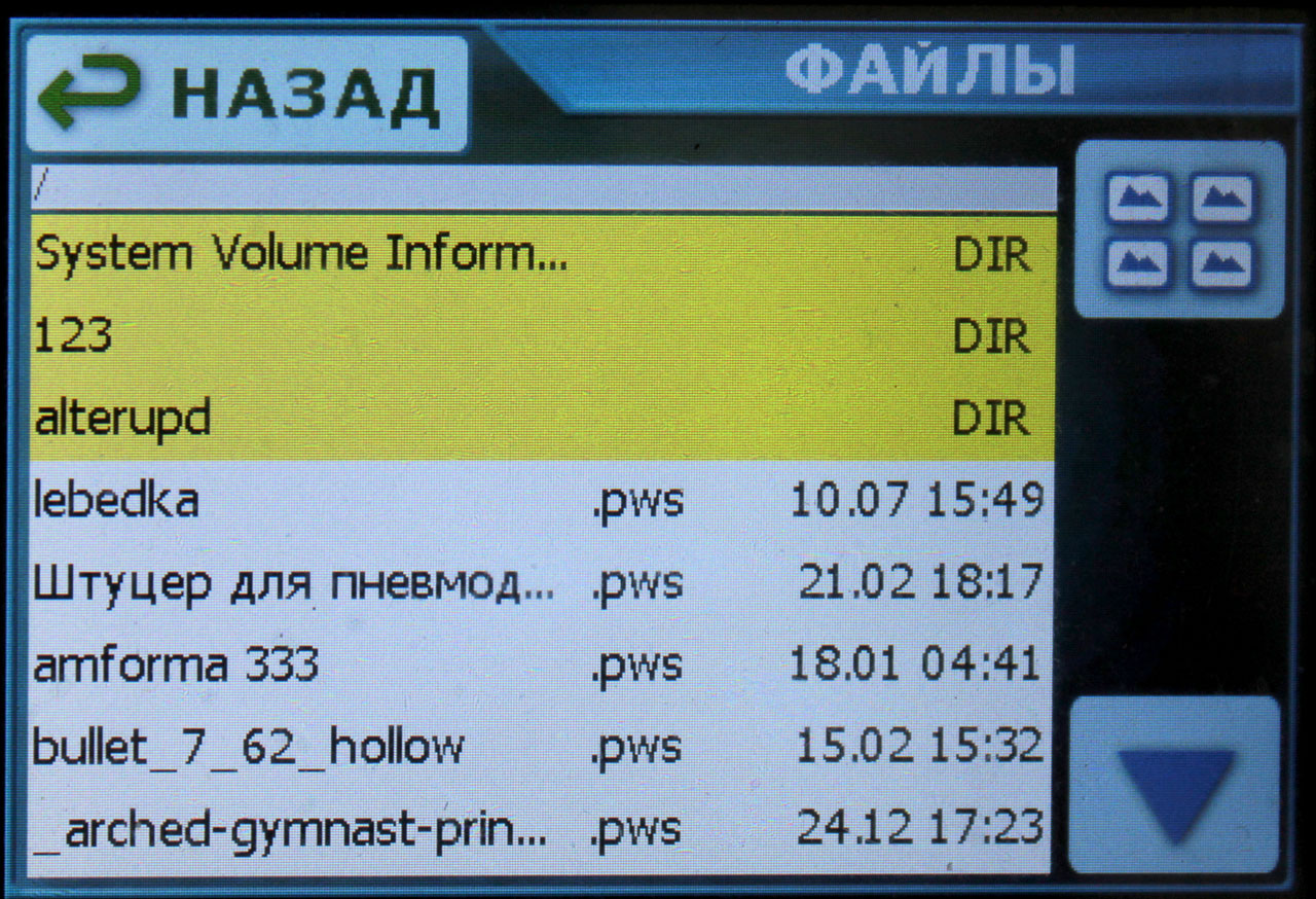
My friend, whom I showed all this to as the firmware was written, suggested another option for outputting files - in the form of a list, a table. Firstly, then more files fit on the page, and secondly, the list is displayed much faster, since you do not need to read preview images from files and draw them with scaling on the display, and thirdly, in a tabular form, you can also display in addition to the name and the time the file was last modified, which is sometimes very convenient. It's a sin to reject a good idea, so I added a table list, and at the same time a button to switch between the "icon" and "table" views. Directories in tabular form are highlighted with a yellow background and the line "DIR" is written instead of time-date:
By the way, there is no intrigue about the preview pictures that are drawn for files in the icon mode. The firmware does not analyze the entire file to build an image from a 3D model, as some think :) This picture is saved in the print file by the slicer itself, in a format similar to BMP - an array of 16-bit pixel color values. The size of the preview image is stored in special fields inside the file. So everything is very simple.
The only thing that the firmware has to strain is in scaling the picture from the file to the size of the icon on the display. The firmware performs scaling in a very simple way: it calculates the scaling factor k(fractional number) - the width of the original image is divided by the width of the display area on the display (the height coefficient is also calculated and the largest of the two values is taken into work) and then pixels and lines are taken from the original image to display on the display with a step of k .
In this way, you can scale both in plus and minus. The quality of the scaled result, of course, leaves much to be desired, since no interpolation is performed, but on such a small and not very high-quality display it is imperceptible, but the speed of such an algorithm is quite high.
When you click on the icon or line of the .pws file, a screen for viewing information about the file opens with the ability to start printing it. If the .acfg file is clicked, then the user is prompted to load the settings from this file. Well, if a directory is pressed, then it becomes current and the list of files is updated.
2.2 Viewing File Information Before Printing
As you correctly noted in the comments to the previous part, Anycubic does not have any information about the file when it is selected. The buttons to start printing and deleting it just appear. And this is very inconvenient - to find out the estimated print time, or the number of layers, or other parameters of this file, you need to start printing it. I decided not to repeat this defect, and when I click on the cut file, a screen opens with the most complete information about it:
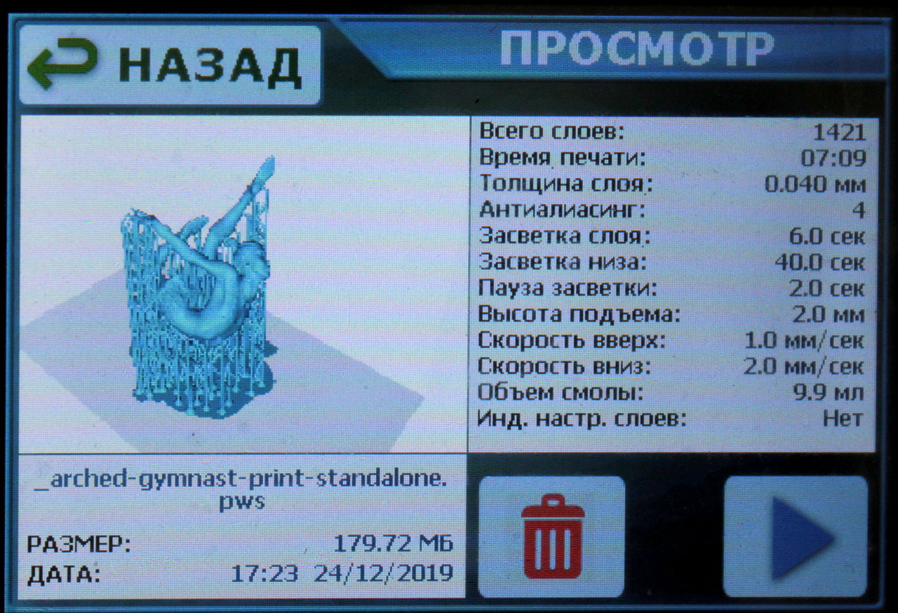
File name, size, time of last modification and almost all print parameters. Here, however, the fact that the MKS DLP display has a resolution of 480x320 played into my hands, while the Enikubiks have a smaller one - 320x240, on this one you can't really swing with a bunch of text.
2.2.1 Regarding the calculation of the printing time, I will write separately.
This indicator is not stored in the file, unlike all other parameters. His printer must calculate independently, based on the information he knows. The same Anycubic Photon S has a habit of overshooting with this calculation, and downward - for example, it promises 5 hours of printing, while in reality it prints 6 hours. And Longer Orange 30 changes this time back and forth almost twice during printing. I decided to approach this point as carefully as possible. What does this time consist of?- The time it takes for the platform to descend at a given speed to the height of the next layer.
- The pause time before the start of exposure.
- Layer exposure time.
- The time it takes for the platform to rise to a given height at a given speed after the layer is exposed.
These 4 parameters are summed up, multiplied by the number of layers and the total print time is obtained. If everything is elementary with pause and flare times - they are maintained with millisecond precision, but with the movement of the platform, everything is already a little more complicated.
The platform does not pick up the set speed instantly, it has some acceleration, which is set in the settings. Moreover, when printing, this is a rather small acceleration, since the platform should begin to rise very smoothly so that the last cured layer painlessly comes off the film at the bottom of the bath (yes, the polymer sticks to the film too, unfortunately).
It turns out that the movement of the platform consists of three components - acceleration until a given speed is reached, uniform movement at a given speed, and deceleration to a complete stop. And this is where the options begin - for example, the specified acceleration and lift height do not allow the platform to reach the specified speed, it is still accelerating at the moment when it already needs to start decelerating in order to stop at the specified height. Or the acceleration and altitude are sufficient for the platform to accelerate to the set speed and travel some part of the path in steady motion before starting to decelerate. We need to check all this, calculate the times and distances for each component.
To be honest, my head was spinning when I wrote the function for calculating the print time :) And as a result I still got a small error. For example, the real print time is 07:43:30 instead of the estimated 07:34:32.
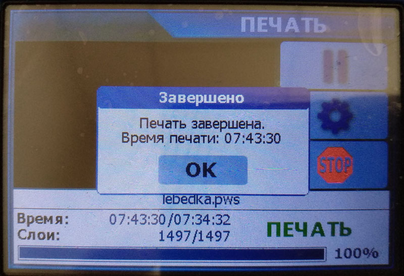
Or 05:48:43 instead of the calculated 05:43:23.
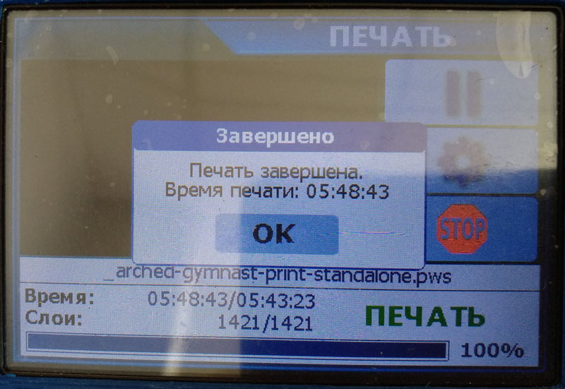
But in principle, this error suited me. I tried to find an error in the calculations, but everything seems to be correct there. Most likely, the actual acceleration slightly does not correspond to the specified one due to the peculiarities of the stepper motor control. So smoothly we came to the next stage :)
3. Stepper motor control for platform movement.
At first I had the thought to write my own stepper motor control. It's not difficult at all, having a normal driver on the board - set the direction of rotation on one pin and drove the pulses of steps to the other pin. You need to rotate quickly - you raise the pulse frequency, you need to slowly - you decrease it.
But when I started to approach this problem more specifically, I realized that its simplicity is deceiving. No, you can write your own, and it will work, but writing in such a way that it works well is a rather big task. Stepper motors do not like irregularities in steps very much, so it is necessary to ensure good uniformity of step pulses in a fairly wide frequency range - from a few hertz to tens of kilohertz. It is necessary to ensure a smooth increase and decrease in the frequency of the pulses for acceleration and deceleration. It is necessary to accurately count the generated impulses in order to be guaranteed to know in what position the platform is now. It is necessary to calculate the number of pulses and the period of their frequency change in a strictly defined period of time in order to provide the required acceleration.
In short, the task, although feasible, is very, very voluminous, which would take me more than one day. So I decided to pluck the engine management functions out of Marlin . I thought it would be easy ...
First, I took the stepper.cpp file from Marlin's sources - directly controlling the stepper motor. However, it turned out that its work is very dependent on the motion planner from the planner.cpp file, so I had to take it too. Well, to the heap, I also took the endstops.cpp file from there - processing the axis limit switches, since I still needed to process events from them, and here the scheduler and engine control were already associated with this file for limit switches.
I spent a very long time trying to remove all unnecessary from these files and untie them from the rest of the Marlin ecosystem. The fact is that Marlin is sharpened under the control of 6 or 7 steppers at the same time, while their operation may depend on the temperature of several heaters, on the parameters of the plastic, etc. The system is really complicated there. I had to do a lot of redo, mainly removing unnecessary axes and unnecessary extruders and getting rid of a whole bunch of macros that were useful in the original version, but very disturbing in mine. Just for understanding - the size of the sources I took from Marlin has been reduced from 346 to 121 KB. And every line had to be deleted with caution.
Naturally, in the process of this hard pruning, I got a little deeper into the work of the whole system, how it works. To move the axis, the target position of the axis is transferred to the planner through one of its functions (the planner stores the current position). The scheduler calculates the number of steps and their parameters for acceleration, straight-line movement and deceleration and forms from these data a special data packet for the direct motor control function (stepper). There can be several of these packages, the scheduler calculates and creates a new, next package for each new task.
Stepper, working in a timer interrupt, in a free state, requests the next data packet from the scheduler. If the scheduler has a prepared package, it gives it away and considers it as finished. Stepper takes the received packet into work and begins to work out the steps of the engine according to the data from it. Until it completes it, the next packet is not requested.
What is curiously implemented in stepper is that at low speeds it issues one step pulse in each interrupt, adjusting the timer so that the next interrupt occurs after the required period of time. When the required step rate exceeds a certain value, the stepper starts to issue several steps in each interrupt. At the same time, all the timings are chosen so well that the uniformity of the steps is very good, for the sake of curiosity I looked at the oscilloscope.
The scheduler also knows how to "join" adjacent packets. What this means: if the scheduler already has a packet prepared for the stepper and then a new task comes to him, then he forms the next packet and changes the previous one so that as a result of sequential processing of these two packets by the stepper, one smooth movement is obtained.
Let me explain with an example. The planner is free, he receives a task to move the axis forward by 20 mm at a speed of 30 mm / s. The planner generates the first packet, in which it describes the acceleration from zero to 30 mm / s, straight-line motion at this speed and deceleration from this speed to zero. If, before the stepper takes this packet from the scheduler, the scheduler is given a new task to move this axis another 50 mm forward, but already at a speed of 40 mm / s, then the scheduler will not just create a new packet with acceleration from zero, but change the first packet by removing the deceleration and extending the straight-line motion by its distance, and in the created second packet, the acceleration will start not from zero, but from the speed of the previous packet.
The result is one movement in which the axis will accelerate to 30 mm / s, travel 20 mm, then accelerate again to 40 mm / s and travel another 50 mm, slowing down to zero at the end. But this is only if the stepper has not yet managed to pick up the previous package, otherwise these two tasks will be processed as two separate movements with zero initial and final speeds in each of them. Therefore, by the way, in printers with manual platform control, if you press the lift several times in a row in 10 mm increments, the platform will stop after the first 10 mm lift and then continue to move without stopping to the full height clicked by the button.
In the new version of Marlin, a remedy has already appeared against such a "jerky" movement - now the scheduler does not give a stepper packet for a certain time after its formation if this packet is the only one ready. This time is set aside for waiting - will the next task arrive so that you can dock it with the existing one.
3.1 Platform motion control interface
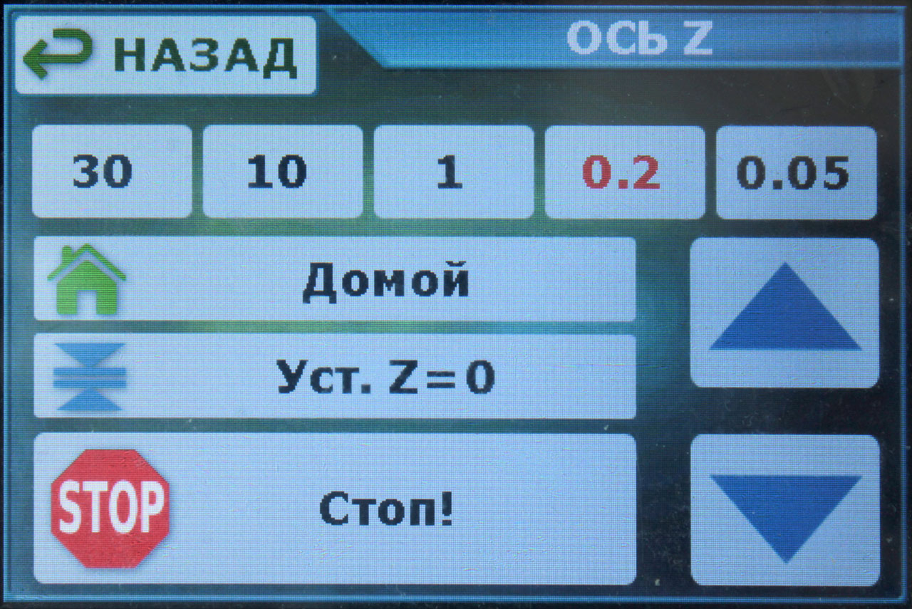
Here, in general, everything is standard and customary for photopolymer printers. At the top is the selection of the step of the axis movement, on the right are the buttons for moving the axis up or down with the selected step.
The "Home" button is used to zero the platform (parking, home), when pressed, the platform begins to move towards the "home" limit switch. Having reached it, the platform stops, moves back a little and again slowly (for greater accuracy) runs into the limit switch. After that, the firmware definitely knows the exact current lift height of the platform.
Set button Z = 0 ”is used to calibrate the platform height above the display. Such a calibration system is used, for example, in Anycubic printers, when the zero point of the platform (its optimal height above the display) is 1-2 mm below the triggering of the "home" limit switch. And this calibration system seems to me to be more correct than the systems that have recently become popular, when the height of the limit switch actuation is at the same time the zero height of the platform.
And the last button is "Stop!" Is an unconditional and immediate stop of the platform movement. By the way, while the platform is in motion, you cannot leave this screen, the "Back" button will not work. This is done just so that while the platform is moving, the "Stop" button is instantly available.
3.2 Other points on platform movement
There are several things that annoy me terribly in Anycubic Photon.
The first is why does the manual movement of the platform occur with the same snail acceleration as in print mode? When typing, such a small acceleration is useful, but when manually controlling the axis, it accelerates for 2 seconds - it's just a nightmare. And the speed of movement is so-so.
The second point - why, when printing is paused, the platform rises to the height of the pause at the speed specified in the print parameters? Hell, waiting 15 seconds for the platform to rise two (only) centimeters is beyond good. But thanks for getting up. In Orange 30, a pause does not at all imply a lifting of the platform even by a millimeter, so it's not even clear why it is there at all.
And the third moment, which just infuriates - after the end of printing, the platform rises to the very top. At the same speed that was specified in the print parameters - 1 mm / sec. It takes 100 seconds to climb up from a height of 5 cm!
Therefore, in my firmware, I made adjustable speeds and accelerations separately for the print mode and separately for manual platform control. But with two limitations:
- Until the axis is reset by the Home button, the travel speed will be reduced by three times. This is because while the printer does not know the exact current platform height, there is a danger of crushing the display without having time to stop at high speed (inertia, so it) or damage the upper axle stop. After zeroing the axis, the printer already knows exactly the position of the platform and the software height limits come into effect, which are also set in the settings.
- At a height of less than 30 mm, the speed is also reduced by three times, regardless of whether the axis is zeroed or not. This is to prevent the photopolymer from splashing out of the bath when the platform is lowered too quickly into it. Or when climbing out of it too quickly.
Of course, there are other standard axis parameters in the settings - the number of steps per 1 mm, the direction of movement, the work of limit switches, etc. If anyone is interested, then under the spoiler there is a text configuration file with all the supported parameters. Such a file with the .acfg extension is eaten by the firmware directly from the file list, loading parameters, saving them to EPROM and applying them immediately, without rebooting:
Configuration file content
# Stepper motor Z axis settings


[ZMotor]


#    .


 #  : 0  1.  : 1.


 #         .


 invert_dir = 1


#       .


 #  : -1  1.  : -1.


 #     -1,


 #    ,   .   1


 #      .


 home_direction = -1


#   Z    .  ,


 #    0,   -   .


 home_pos = 0.0


#         .


 #  :     -32000.0  32000.0.


 #  : -3.0


 #        .


 #     ,    .


 min_pos = -3.0


#         .


 #  :     -32000.0  32000.0.


 #  : 180.0


 #        .


 #     ,    .


 max_pos = 180.0


#   .


 #  : 0  1.  : 1.


 #         ,


 #  1,   -  0.


 min_endstop_inverting = 1


#   .


 #  : 0  1.  : 1.


 #         ,


 #  1,   -  0.


 max_endstop_inverting = 1


#     1   .


 steps_per_mm = 1600


#  ,


 # , /.  : 6.0.


 homing_feedrate_fast = 6.0


#  ,


 # , /.  : 1.0.


 homing_feedrate_slow = 1.0


#     , /2.


 acceleration = 0.7


#      , /.


 feedrate = 5.0


#       (   ,


 #      ..), /2.


 travel_acceleration = 25.0


#       (   ,


 #      ..), /.    30


 #          ,


 # 5 /.


 travel_feedrate = 25.0


#       , .


 current_vref = 800.0


#          , .


 current_hold_vref = 300.0


#      ,


 #    .   .  0


 #    .


 hold_time = 30.0


#      ,


 # .   .


 #   hold_time.  0   .


 #  ,       .


 off_time = 10.0


# General settings


[General]


#      (0.001 )


 #      .


 #  :  0  15000.  : 700 (0.7 ).


 buzzer_msg_duration = 700


#      (0.001 )


 #     ,   .


 #  :  0  15000.  : 70 (0.07 ).


 buzzer_touch_duration = 70


#       180 .


 #            .


 #  : 0  1.  : 0.


 rotate_display = 0


#           ,   .


 #    LCD-.      -


 #  .


 #  :  0  15000.  : 10.  0   .


 screensaver_time = 10
And with that I will finish this part, and already there is too much text :)
As before - I will be happy to answer questions and accept comments.
- Part 1: 1. User interface.
- Part 2: 2. Working with the file system on a USB-stick. 3. Stepper motor control for platform movement.
- Part 3: 4. Displaying images of layers on the backlight display. 5. Every little thing, such as controlling lighting and fans, loading and saving settings, etc. 6. Additional features for comfort and convenience.
Links
MKS DLP kit on Aliexpress
Original firmware sources from the manufacturer on GitHub
Schemes from the manufacturer of two versions of the board on GitHub
My sources on GitHub