... or how I invented my own bicycles with preferences and geishas to my taste - I wrote firmware for a photopolymer printer from scratch. At the moment, the firmware is already fully functional.
The MKS DLP board sold on Aliexpress was taken as a basis, for which the manufacturer provides the circuit and the source codes for the firmware, which I rejected in favor of writing everything from scratch.
The article turns out to be very long, so I decided to split it into two parts. In this part, there will be a background and description of a homemade GUI for a touch screen. At the end there will be links to the subject of bullying itself and to the GitHub repositories.
- Part 1: 1. User interface.
- Part 2: 2. Working with the file system on a USB-stick. 3. Stepper motor control for platform movement.
- Part 3: 4. Displaying images of layers on the backlight display. 5. Every little thing, such as controlling lighting and fans, loading and saving settings, etc. 6. Additional features for comfort and convenience.
For a better understanding, I will give a very short description of the work of photopolymer LCD 3D printers for those who are not familiar with them:
A short explanation of how most 'consumer' photopolymer printers work
— LCD- ( , 5.5" 25601440 ( — 47.25 ). 405 . , FEP-. , «» . , -. , «» , . . , , . , . , .
Background
How did I come to this and why I began to write my own firmware instead of just tweaking the source code from the manufacturer for myself.
The backstory turned out to be long, so I removed it under the spoiler
5 3D-. , , . FDM-, — Anet A8. - , , . - — - , , . , . - — Anycubic Photon S. , .
, , «» — , . , .., FDM-. , , — 11565 , :) «» , , , . . «» — . , , 20-30 . , — , . .
. , , .. , , , , , . . , (), . , , . - . , 3D- — MKS DLP. : , (5.5", 25601440) (3.5", 480320). — ! , , .
, , . , - , , . . , . … -, CMSIS HAL ST ( STM32F407). -, Marlin 3D. — Marlin 3D — FDM 3D-. 6 , , , G- - . 3 . . — G- . , . , FDM- .
, GUI- , . , , - .
So what we have:
- MKS DLP kit, which includes: motherboard, 3.5 "480x320 interface display and 5.5" 2560x1440 backlight display
- native sources from the manufacturer
- motherboard diagram (without names of active and nominal values of passive components)
The motherboard is based on the STM32F407 microcontroller. To control the backlight display, the board contains an FPGA from the Chinese manufacturer GW1N-LV4LQ144ES, SDRAM and two SSD2828 MIPI interface chips. The microcontroller drives the image of the layer into the FPGA, the FPGA stores it in SDRAM and from there refreshes the display through the SSD2828. By the way, the manufacturer does not provide the FPGA configuration (firmware) in the source code: (In addition, the motherboard has:
- power input 12-24 volts
- USB A /
- A4988
- Z —
- WiFi
- FLASH- W25Q64
- EEPROM- AT24C16
The interface display with a resistive touch panel is connected with a flat 40-pin cable. Display controller - ILI9488, touch panel controller - HR2046 (similar to TSC2046).
To initialize the peripherals, I used the STM32CUBE MX program. But I did not use the result obtained from it directly, but inserted the necessary pieces into my sources. When working with peripherals, I used the HAL libraries from ST, and where I needed to get the maximum speed, I worked with registers directly.
So, there is a task - this kit should be able to print files from a flash drive with ease for the user. I divided this whole problem roughly into main parts, which resulted in three publications.
I want to warn you right away that neither my code nor my approach at all pretend to be ideal or even just good, I play as I can. For me, programming is more of a hobby than a profession. So please do not judge by too strict standards.
1. User interface
First was the initialization of the display. There is nothing interesting here, the standard sequence for the ILI9488 controller. I ripped it out from native sources, cutting out the initialization code for other types of displays (which, probably, remained there from the FDM life of these sources). Then I took up fonts.
1.1 Fonts
There are many font libraries for microcontrollers on the net, but the vast majority of them work with monospaced fonts, and I don't really like that. This is when all characters have the same width, like the letter "z", that the letter "i". I once wrote a proportional font library for one of my pet projects. It uses two arrays for each font - an array with the bit data of the characters themselves and an array with the width of each character. And a small structure with font parameters - pointers to arrays, font height, number of characters in the font:
typedef struct
{
	uint16_t	*width;
	uint8_t		*data;
	uint8_t		height;
	uint16_t	symcount;
} LCDUI_FONT;
It would seem that such a font organization should take up more memory space than just a monospaced bitmap, but this is not entirely true. First, the monospace itself gives rise to a surplus of stored data. For example, if in a font 8 pixels high and 5 pixels wide, 1 byte (1 bit wide and 8 bits high) would be enough for the letter "i", then it will still take 5 bytes of data (5 bits wide and 8 bits high), since the width is fixed. Secondly, as a rule, in such fonts, alignment is done on the byte boundaries of each line or each column, depending on how the data is organized.
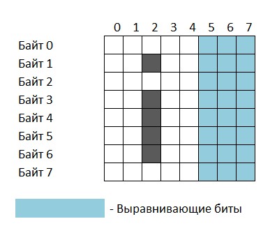
For example, take the same 5x8 font. If the bit data is stored line by line, then there is an excess of 3 bits for each line. Or 3 bytes per character:
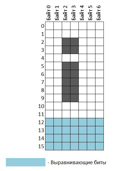
Or a 7x12 font with data storage in columns, then there is an excess of data of 4 bits per column or 3.5 bytes per character:
In my library, bit data is continuous for a character and alignment on the byte boundary is only at the end of the character.
Plus there is one more little trick that allows you to slightly reduce the stored font size: a character may not have bit data, but refer to another character with the same style. For example, the Cyrillic letters "A", "B", "E", "K", etc. can have a reference to Latin letters with the same style. This is done by specifying a negative value for the width of the corresponding character in the array of character widths. If there is a negative value there, then the image of this character is taken from the character in position (width * -1).
Here is the procedure for finding a character in an array:
uint8_t*	_lcdui_GetCharData(char c)
{
	if (c < 32)
		return 0;
	if (c > 126)
		c -= 65;
	c -= 32;
	if (c >= lcdui_current_font->symcount)
		return 0;
	uint16_t c1 = lcdui_current_font->width[c];
	if (c1 & 0x8000)
		c = (c1 & 0x7FFF);
	uint16_t ch = lcdui_current_font->height;
	int32_t i = 0, ptr = 0, bits = 0, line_bits = ch;
	for (i = 0; i < c; i++)
	{
		if (lcdui_current_font->width[i] & 0x8000)
			continue;
		bits = lcdui_current_font->width[i] * line_bits;
		ptr += bits >> 3;
		if (bits & 0x07)
			ptr++;
	}

	return &(lcdui_current_font->data[ptr]);
}
All this often gives even a gain in the amount of data for the font. Not to mention, proportional type looks more natural.
The rendering speed of such a font is quite decent due to the windowed output - the display is first given the command to limit the output window to the size of the character in the desired position, and then the data of the entire character is poured into it in one stream. There is no need to set coordinates separately for each pixel.
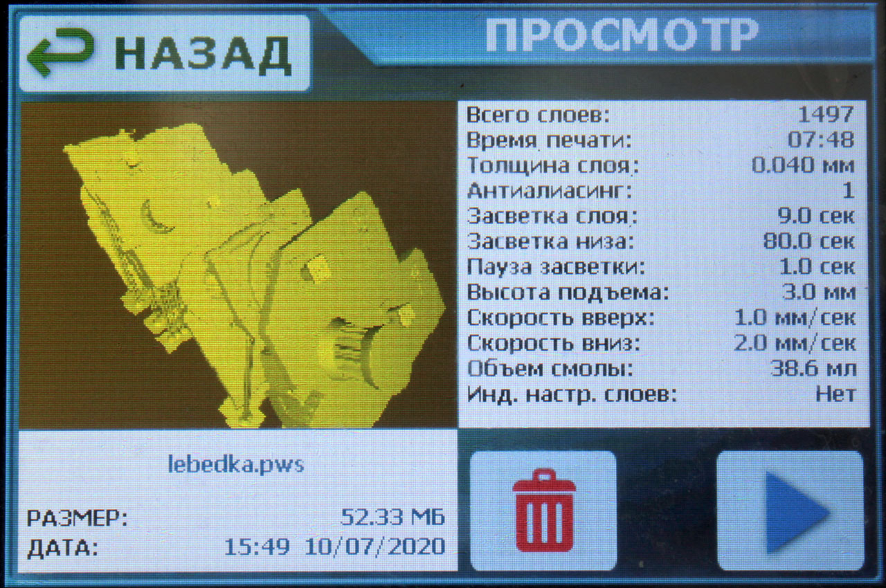
For example, in the photo below, the blue text and the top white line were rendered by my library, and the white bottom line - by the standard arduino-like library from the native sources: The

blue text was rendered several times faster than the bottom white line.
At the same time, I had to invent a utility for creating font arrays ready for use in a program from an image. In Photoshop, an image of the desired height is created with all the characters of the font, then the X coordinates of the last column of each character are entered into the text file by hand, and then the utility is set on the image and this text file. This creates a .c file with the required arrays. A bit tedious, of course, but simple.
The procedure for displaying text is able to wrap text to a new line at the end of the screen or by a line feed character encountered, can align to the left, right and center, limit the area beyond which the text will not go (will be cut off). And it is able to display symbols with background painting with background color or with background preservation. The second option works slower, since it is no longer possible to fill the character data into the display in one stream, but it is still fast enough that the output of 3-4 lines is not visible to the eye.
1.2 Displaying interface images
For the user interface, you will need to display images - background, icons, buttons. At first I decided not to bother too much and store all images in .bmp format in the 8MB flash memory available on the board. And I even wrote a procedure for this. The file is saved in 16-bit format (R5 G6 B5) with end-to-end or end-to-end line order, and may already be directly fed to the rendering routine. But the size of a 480x320 background image is more than 300 KB. Considering that some of this flash memory will be dedicated to firmware updates, 30 background images will take up all of the memory. It seems to be a lot, but still less than I would like to have, just in case. But there should also be buttons, icons, etc. Therefore, it was decided to convert the images to some kind of compressed format.
There are not many options with compression - all algorithms that compress images more or less well require either decent RAM (by the standards of a microcontroller) or a decent amount of time to decompress. Pictures, on the other hand, should be displayed, unclenching on the fly, and it is desirable that the picture when displaying does not resemble a crawling progress bar. Therefore, I settled on RLE compression - 1 byte encodes the number of repetitions, and the two following it - the color. For this, a utility was also written that converts .bmp files into images compressed in this way. The header consists of only 4 bytes - 2 bytes for the width and height of the image. On average, background images are compressed in this way by 5-7 times, strongly depends on the size of monochrome areas (which is to be expected). For example, a picture like this shrunk from the original 307 KB to 74 KB:

But this one - up to 23 KB from the same 307:

By the way, the designer of me is even more crap than the programmer ...
I was satisfied with this result. Decoding and displaying images is very fast - about 40 milliseconds per full background image. So I settled on this option.
And by the way, switching to DMA mode for outputting data to the display did not give almost any acceleration of output. The display is connected via an external 16-bit data bus as an external memory, but its timings are rather sad, which almost negates the advantages of DMA output over manual pixel output.
1.3 GUI framework
Texts are displayed, pictures are drawn, now it's time to think about how the basis of the user interface will be organized.
With the touch panel, everything is simple - the microcontroller constantly polls the touch panel controller for interrupts and averages the last 4 obtained results, translating them into display coordinates. Thus, the state of the sensor is known at any moment - whether it is pressed or not, and if it is pressed, then in which place. Another layer between the touch panel and the main part of the program is the procedure for processing button clicks, which has been wandering from project to project with small adaptations for specific conditions for quite some time.
Here is a brief summary of how it works.
«». (100-150 ). , «». , . , , «», . , «», «». «», «». - «» «», . ( «»), - . , , .
The touch panel serves as the only interface button, only besides the very fact of pressing it, the coordinates of the click are also analyzed.
Now everything needs to be done so that a variety of interface elements can be displayed on the screen, which might or might not respond to clicks, update by events, have different sizes and images, etc.
Ultimately, I came to this scheme: the interface consists of two main types of elements - screens and buttons.
A screen is a kind of full-screen container for buttons. The screen has the following properties:
- background image
- background color
- way of drawing the background - filling with a background color or displaying an image
- header text
- title text color
- header text font
- a pointer to the parent screen (which to return to when closing this)
- an array of pointers to buttons
- a pointer to an event procedure (called periodically in the main program loop)
- pointer to the screen drawing routine
Screen structure
typedef struct
{
	void				*addparameter;

	char				*bgimagename;

	void				*prevscreen;

	LNG_STRING_ID		name;
	TG_RECT				nameposition;
	TG_TEXTOPTIONS		nameoptions;

	uint8_t				btns_count;
	TG_BUTTON			*buttons;

	LCDUI_FONT_TYPE		font;
	LCDUI_FONT_TYPE		namefont;
	uint16_t			textcolor;
	uint16_t			nametextcolor;
	uint16_t			backcolor;

	struct {
		paintfunc		_callpaint;	// repaint screen
		processfunc		_process;	// screen process handling (check for changes, touch pressed, etc)
	} funcs;
} TG_SCREEN;
Buttons in fact can be not only buttons, but also text, an icon, some kind of changing element such as a counter or a clock. It just turned out to be convenient to combine everything in one type, and set the behavior of each specific button through its properties.
Button properties:
- coordinates on the screen
- background color
- background image for free state
- background image for the pressed state
- background image for disabled state
- background image for active state (for active element of a radio button group, for example)
- rendering method - image or background color
- Whether to redraw the button when pressed and released
- button text
- ( )
- (, )
- ( )
- ,
- ,
typedef struct
{
	void				*addparameter;

	uint8_t				button_id;


	int8_t				group_id;		// for swithed options buttons, >0 - single selection from group (select), <0 - multiple selection (switch)

	TG_RECT				position;

	void				*parentscreen;
	void				*childscreen;

	char				*bgimagename_en;
	char				*bgimagename_press;
	char				*bgimagename_dis;
	char				*bgimagename_act;	// for swithed options buttons

	LNG_STRING_ID		text;
	TG_RECT				textposition;
	LCDUI_FONT_TYPE		font;
	uint16_t			textcolor_en;
	uint16_t			textcolor_press;
	uint16_t			textcolor_dis;
	uint16_t			textcolor_act;	// for swithed options buttons
	uint16_t			backcolor_en;
	uint16_t			backcolor_press;
	uint16_t			backcolor_dis;
	uint16_t			backcolor_act;	// for swithed options buttons

	struct {
		uint8_t				active:1;		// for swithed options buttons
		uint8_t				needrepaint:1;
		uint8_t				pressed:1;
		uint8_t				disabled:1;
		uint8_t				repaintonpress:1;		// repaint or not when pressed - for indicate pressed state
		BGPAINT_TYPE		bgpaint:2;
	} options;

	TG_TEXTOPTIONS	textoptions;

	struct {
		paintfunc		_call_paint;	// repaint button
		pressfunc		_call_press;	// touch events handling
		pressfunc		_call_longpress;	// touch events handling
		processfunc		_call_process;	// periodical processing (for example text value refresh)
	} funcs;
} TG_BUTTON;
With the help of this set of properties, it became possible to create almost anything in the interface based on such an element. If a screen or a button has a pointer to any of the procedures null, then the corresponding standard procedure is called. Instead of a procedure pointer for pressing a button, for example, there may be a special identifier indicating that you need to go to the child or previous screen, then the standard procedure will do it. In general, standard procedures cover almost all cases of using ordinary buttons and you have to create your own procedures for a button only in non-standard cases - for example, when a button works like a clock, or as an element of a file list.
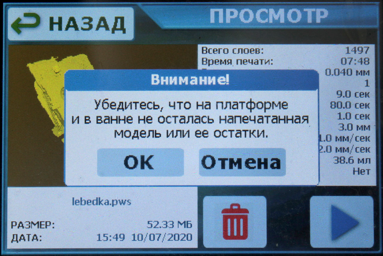
But what the capabilities of this scheme were lacking was for modal windows with messages or questions (like MessageBox in the Windows API), so I made a separate type of screens for them. No background images and a size determined by the title or the message itself. These messages can be created in four versions - with "Yes / No" buttons, with "OK / Cancel" buttons, with one "OK" button, or without buttons at all (such as "Wait, data is loading ...").
Structure of the message box
typedef struct
{
	MSGBOXTYPE			type;

	void				*prevscreen;

	char				caption[128];
	char				text[512];
	TG_RECT				boxpos;

	uint8_t				btns_count;
	TG_BUTTON			buttons[TG_BTN_CNT_MSGBOX];

	uint16_t			caption_height;

	LCDUI_FONT_TYPE		font_caption;
	LCDUI_FONT_TYPE		font_text;
	uint16_t			text_color;
	uint16_t			box_backcolor;
	uint16_t			capt_textcolor;
	uint16_t			capt_backcolor;
} TG_MSGBOX;
It was on the basis of these three types that the entire interface was built, it turned out to be quite flexible. Now the initialization of all elements is carried out rigidly in the firmware, but there is an idea to give users the opportunity to create their own interface by describing the properties of all elements in the configuration file and adding a number of necessary pictures. In theory, it will be possible to change the contents of different screens - which buttons to put on the main screen, which buttons to the service screen, etc.
1.4 Multilanguage
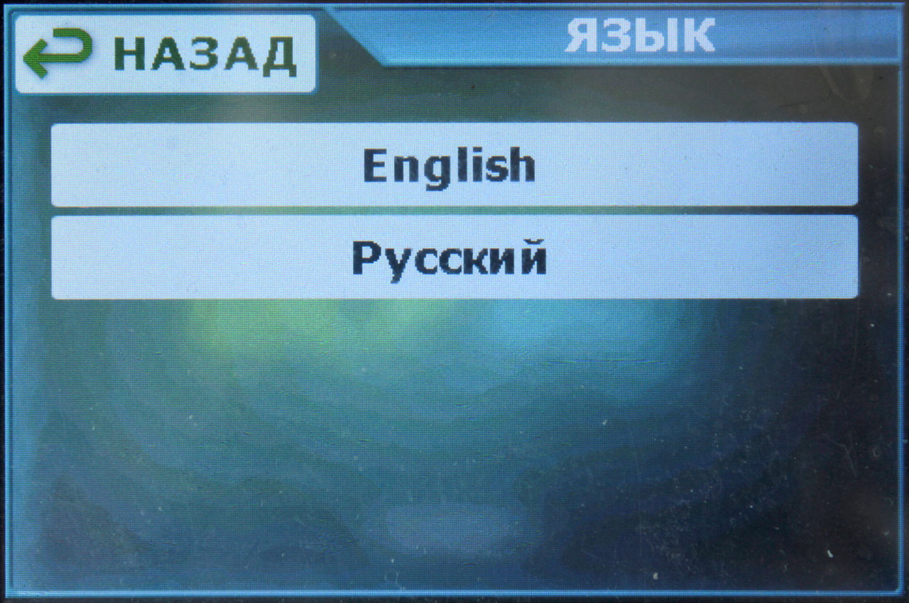
Multilingualism was in the tasks initially. But at first I went down the stupid path - when initializing all the elements, I assigned them texts from the language table that was the current one. Switching the language meant re-initializing all text elements, and when there were more than two screens in the interface, and more than 20 buttons and labels, I realized that it was impossible to live like this any longer. Then he made all the references to the texts through the procedure. The procedure is given a text identifier as a parameter, and it returns a pointer to the text in the current language:
char *mshortname = LANG_GetString(LSTR_SHORT_JANUARY);
When changing the language, the pointer simply changes from an array of texts in the old language to an array with texts in the new language:
void		LANG_SetLanguage(uint8_t lang)
{
	lngCurrent = lngLanguages[lang].strings;

	return;
}
All source texts are in UTF-8 encoding. I also had to tinker with these encodings. Texts - in UTF-8, Cyrillic files - in Unicode-16, some strings - in regular ANSI. I didn't want to pull into the firmware a whole set of libraries to support multibyte encodings, so several functions were written for converting from encoding to encoding and for operations with texts in different encodings, for example, adding a UTF-8 string to the end of a Unicode16 string.
Adding a new language has now boiled down to creating a table of texts in it and changing the value of the constant LNG_LANGS_COUNT. True, there remains a question with fonts, if the new language uses symbols other than Cyrillic and Latin ... Now I support Russian and Google-translated English in the source code.
1.5 Storing images and other resources
For storing large resources, the board has an 8 megabyte SPI flash W25Q64. Initially, I wanted to do as always - set an offset for each resource inside the flash and save them there as just binary data. But then I realized that problems with this method are guaranteed to me as soon as the number of saved resources exceeds a couple of dozen and I want to change, for example, some picture that is saved sixth in order. If its size increases, you will have to shift the addresses of all the following resources and rewrite them. Or leave a spare space of unknown size after each resource - who knows how any of the resources can change. Yes, I saw this fuss in the coffin :) So I spat and organized a file system on this flash.By that time, I already had a USB file system based on the FatFS library, so it was enough for me to simply write separate low-level read / write functions for sectors. Only one thing slightly upset me - the size of the erased sector in this microcircuit is already as much as 4 KB. This firstly leads to the fact that the files will take up space in portions of 4 KB (the file was written 200 bytes - it took 4 KB of flash), and secondly, the buffer in the structure of each file pointer will eat off the same 4 KB of RAM, which in the microcontroller is not that much - 192 KB. One could, of course, be perverted and write low-level functions so that they could write and read in smaller portions, reporting on the sector size, for example, 512 bytes. But that would slow down the Flash, so it left the sector size at 4KB.So any resource can be accessed simply by its file name, which turned out to be very convenient. At the moment, for example, the number of stored resources has already exceeded 90. And I made their updating as simple as possible - the updated (or new) resources are written to a USB flash drive in a certain directory, the flash drive is inserted into the board, the board is rebooted into the service mode (during turn on or reboot, press and hold the upper right corner of the display) and automatically copies all files found in this directory from the USB flash drive to the SPI flash.the board reboots into service mode (during power on or reboot, press and hold the upper right corner of the display) and automatically copies all files found in this directory from the USB flash drive to the SPI flash.the board reboots into the service mode (during power-up or reboot, press and hold the upper right corner of the display) and automatically copies all files found in this directory from the USB flash drive to the SPI flash.

To be continued...
Perhaps the most voluminous part came out on the interface. If this article turns out to be of interest to the community, then in the second part I will try to accommodate everything else.
Well, I will be glad to questions and comments.
- Part 1: 1. User interface.
- Part 2: 2. Working with the file system on a USB-stick. 3. Stepper motor control for platform movement.
- Part 3: 4. Displaying images of layers on the backlight display. 5. Every little thing, such as controlling lighting and fans, loading and saving settings, etc. 6. Additional features for comfort and convenience.
Links
MKS DLP kit on Aliexpress
Original firmware sources from the manufacturer on GitHub
Schemes from the manufacturer of two versions of the board on GitHub
My sources on GitHub