At SberDevices we make devices on which you can listen to music, watch movies and much more. As you can imagine, without sound, this is all of no interest. Let's take a look at what happens to the sound in the device, from school physics to the ALSA subsystem in Linux.
What is the sound that we hear? To simplify completely, these are vibrations of air particles that reach our eardrum. Their brain, of course, then translates into pleasant music or into the sound of a motorcyclist passing outside the window, but let's dwell on vibrations for now.
Back in the 19th century, people realized that you can try to record sound vibrations and then reproduce them.
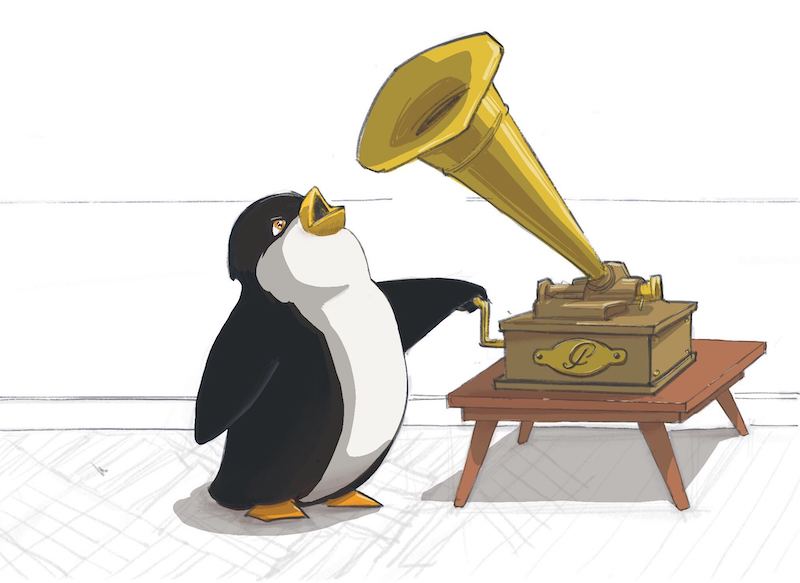
First, let's take a look at how one of the first recording devices worked.
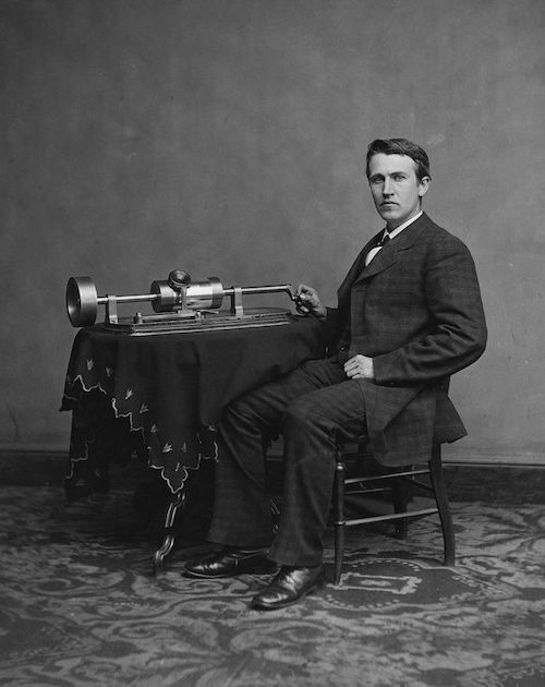
The phonograph and its inventor Thomas Edison
Photo source
Everything is simple here. They took a cylinder and wrapped it in foil. Then they took something cone-shaped (to make it louder) with a membrane at the end. A small needle is attached to the membrane. The needle was leaned against the foil. Then a specially trained person twisted the cylinder and said something into the resonator. A needle, driven by a membrane, made indentations in the foil. If it is enough to evenly twist the cylinder, then the dependence of the membrane oscillation amplitude on time "wound" on the cylinder will turn out.
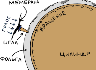
To play the signal, you just had to turn the cylinder again from the beginning - the needle will fall into the recesses and transmit the recorded vibrations to the membrane, and that to the resonator. So we hear the recording. You can easily find interesting posts by enthusiasts on YouTube.
Transition to electricity
Now let's look at something more modern, but not very complicated. For example, a reel microphone. Oscillations of air now change the position of the magnet inside the coil, and thanks to electromagnetic induction, we get at the output the dependence of the amplitude of oscillations of the magnet (and hence the membrane) on time. Only now this dependence is expressed not by depressions on the foil, but by the dependence of the electric voltage at the output of the microphone on time.
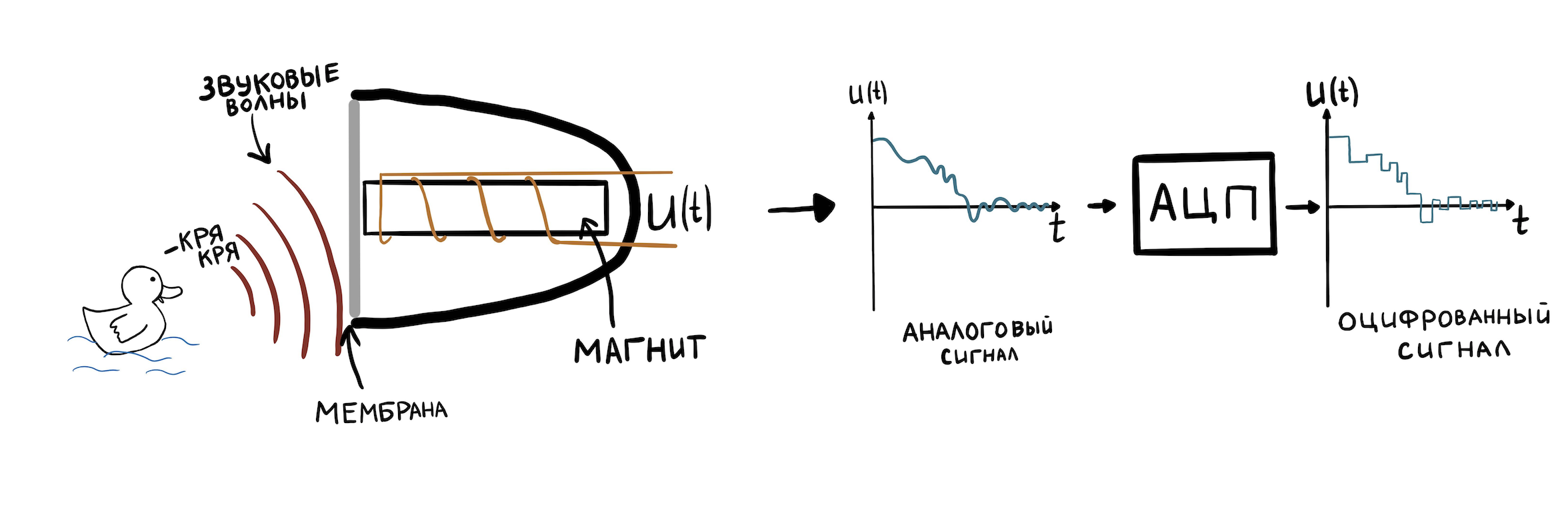
To be able to store such a representation of fluctuations in the computer memory, they must be discretized. This is done by a special piece of hardware - an analog-to-digital converter (ADC). The ADC is able to memorize the voltage value (up to the resolution of the ADC integer arithmetic) at the input many times in one second and write it to memory. The number of such samples per second is called the sample rate. Typical values are 8000 Hz - 96000 Hz.
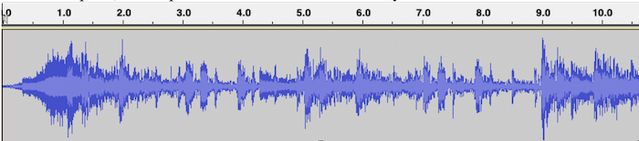
We will not go into the details of the ADC, because it deserves a separate series of articles. Let's move on to the main thing - all the sound with which Linux drivers and all sorts of devices work is represented precisely in the form of an amplitude versus time dependence. This recording format is called PCM (Pulse-code modulation). For each time slice with duration 1 / sample_rate, the value of the sound amplitude is indicated. .Wav files are composed of PCM.
An example of PCM visualization for a .wav file with music, where the horizontal axis is time, and the vertical axis is the signal amplitude:
Since our board has a stereo output for speakers, you need to learn how to store stereo sound in one .wav file: left and right channels. Everything is simple here - the samples will alternate like this:
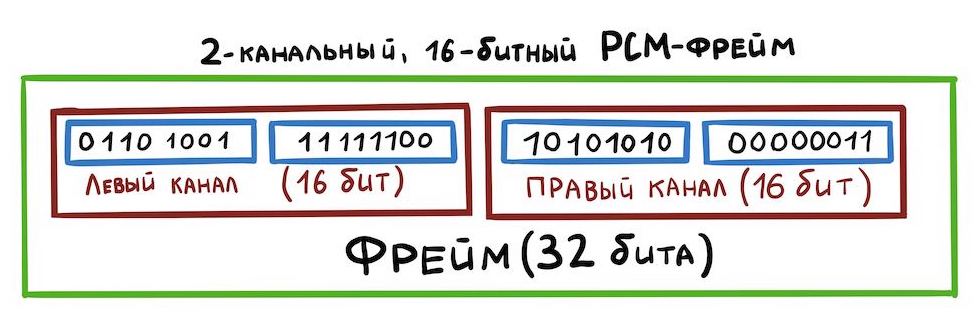
This way of storing data is called interleaved. There are other ways, but we will not consider them now.
Now let's figure out what electrical signals we need in order to organize the transfer of data between devices. And not much is needed:
- Bit Clock (BCLK) is a clock signal (or clock) by which the hardware determines when to send the next bit.
- Frame Clock (FCLK or it is also called LRCLK) is a timing signal by which the equipment understands when it is necessary to start transmitting another channel.
- Data is the data itself.
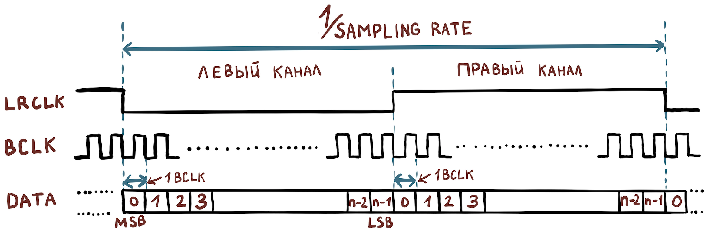
For example, we have a file with the following characteristics:
- sample width = 16 bits;
- sampling rate = 48000 Hz;
- channels = 2.
Then we need to set the following frequency values:
- FCLK = 48000 Hz;
- BCLK = 48000 * 16 * 2 Hz.
To transmit even more channels, the TDM protocol is used, which differs from I2S in that FCLK is no longer required to have a duty cycle of 50%, and the rising edge only sets the beginning of a packet of samples belonging to different channels.
General scheme
Right at hand was the amlogic s400 board, to which you can connect a speaker. It has the upstream Linux kernel installed. We will work on this example.
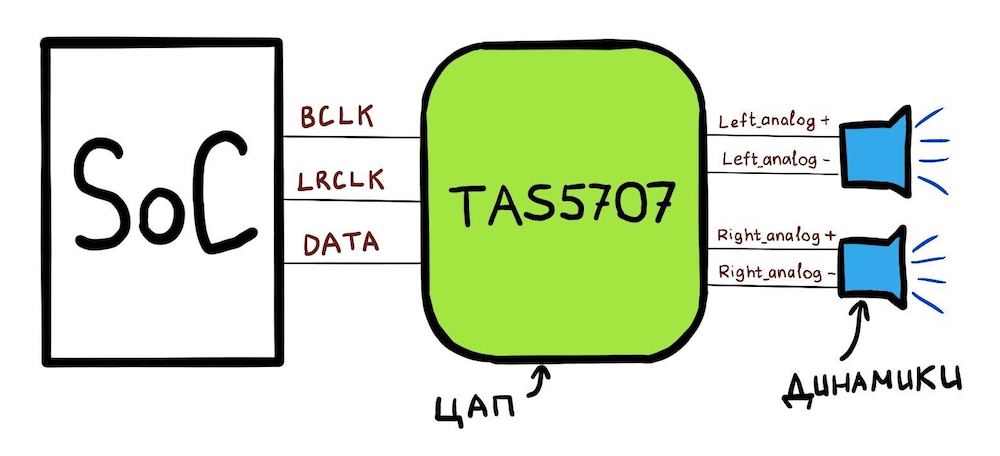
Our board consists of a SoC (amlogic A113x) to which the TAS5707PHPR DAC is connected. And the general scheme looks like this:
What SoC can do:
- SoC has 3 pins: BCLK, LRCLK, DATA;
- you can configure the CLK pins through the special registers of the SoC so that they have the correct frequencies;
- You can also say to this SoC: “Here's an address in memory. It contains PCM data. Send this data bit by bit through the DATA line. " This memory area will be called hwbuf.
To play sound, the Linux driver tells the SoC which frequencies to set on the BCLK and LRCLK lines. In addition, the Linux driver tells you where hwbuf is located. The DAC (TAS5707) then receives the data via the DATA line and converts it into two analog electrical signals. These signals are then transmitted over a pair of wires {analog +; analog-} into two speakers.
Moving on to Linux
We are ready to move on to how this circuit looks in Linux. First, there is a "library" for working with sound in Linux, which is spread between the kernel and userspace. It is called ALSA, and we will consider its name. The essence of ALSA is for userspace and the kernel to "agree" on the interface for working with sound devices.
The custom ALSA library interacts with the kernel using the ioctl interface. The pcmC {x} D {y} {c, p} devices created in the / dev / snd / directory are used. These devices are created by a driver that must be written by the SoC vendor. For example, the contents of this folder on amlogic s400:
# ls /dev/snd/
controlC0    pcmC0D0p   pcmC0D0   pcmC0D1c   pcmC0D1p   pcmC0D2c
In the name of pcmC {x} D {y} {c, p}:
X - sound card number (there may be several of them);
Y - the number of the interface on the card (for example, pcmC0D0p can be responsible for playing back to speakers via the tdm interface, and pcmC0D1c for recording sound from microphones via a different hardware interface);
p - says that the device for playing sound (playback);
c - says that the device for recording sound (capture).
In our case, the pcmC0D0p device exactly corresponds to the playback I2S interface. D1 is spdif and D2 is pdm microphones, but we won't talk about them.
Device tree
Soundcard description starts with device_tree [arch / arm64 / boot / dts / amlogic / meson-axg-s400.dts]:
…

sound {
    compatible = "amlogic,axg-sound-card";
    model = "AXG-S400";
    audio-aux-devs = <&tdmin_a>, <&tdmin_b>,  <&tdmin_c>,
             <&tdmin_lb>, <&tdmout_c>;
           …

    dai-link-6 {
        sound-dai = <&tdmif_c>;
        dai-format = "i2s";
        dai-tdm-slot-tx-mask-2 = <1 1>;
        dai-tdm-slot-rx-mask-1 = <1 1>;
        mclk-fs = <256>;
        codec-1 {
            sound-dai = <&speaker_amp1>;
        };
    };
           …
    dai-link-7 {
        sound-dai = <&spdifout>;
        codec {
            sound-dai = <&spdif_dit>;
        };
    };
    dai-link-8 {
        sound-dai = <&spdifin>;
        codec {
            sound-dai = <&spdif_dir>;
        };
    };
    dai-link-9 {
        sound-dai = <&pdm>;
        codec {
            sound-dai = <&dmics>;
        };
    };
};

…

&i2c1 {
    speaker_amp1: audio-codec@1b {
        compatible = "ti,tas5707";
        reg = <0x1b>;
        reset-gpios = <&gpio_ao GPIOAO_4 GPIO_ACTIVE_LOW>;
        #sound-dai-cells = <0>;
               …
    };
};
&tdmif_c {
    pinctrl-0 = <&tdmc_sclk_pins>, <&tdmc_fs_pins>,
            <&tdmc_din1_pins>, <&tdmc_dout2_pins>,
            <&mclk_c_pins>;
    pinctrl-names = "default";
    status = "okay";
};
Here we see those 3 devices that will then appear in / dev / snd: tdmif_c, spdif, pdm.
The device through which the sound will go is called dai-link-6. It will work under the control of the TDM driver. The question arises: we were talking about how to transmit sound via I2S, and then, suddenly, TDM. This is easy to explain: as I wrote above, I2S is still the same TDM, but with clear requirements for the LRCLK duty cycle and the number of channels - there should be two of them. The TDM driver will then read the dai-format = "i2s" field; and will understand that he needs to work in I2S mode.
The following indicates which DAC (within Linux they are referred to as a “codec”) is installed on the board using the speaker_amp1 structure. Note that it is immediately indicated to which I2C line (not to be confused with I2S!) Our TAS5707 DAC is connected. It is along this line that the amplifier will then be turned on and tuned from the driver.
The tdmif_c structure describes which SoC pins will act as the I2S interface.
ALSA SoC Layer
For SoCs that have audio support inside, Linux has an ALSA SoC layer. It allows you to describe codecs (remember that this is what any DAC is called in ALSA terms), allows you to specify how these codecs are connected.
Codecs in Linux kernel terms are called DAI (Digital Audio Interface). The TDM / I2S interface itself, which is in the SoC, is also called DAI, and work with it is carried out in a similar way.
The driver describes the codec using struct snd_soc_dai. The most interesting part in the description of the codec is the operation for setting the TDM transmission parameters. They are located here: struct snd_soc_dai -> struct snd_soc_dai_driver -> struct snd_soc_dai_ops. Let's consider the most important fields for understanding (sound / soc / soc-dai.h):
struct snd_soc_dai_ops {
    /*
     * DAI clocking configuration.
     * Called by soc_card drivers, normally in their hw_params.
     */
    int (*set_sysclk)(struct snd_soc_dai *dai,
        int clk_id, unsigned int freq, int dir);
    int (*set_pll)(struct snd_soc_dai *dai, int pll_id, int source,
        unsigned int freq_in, unsigned int freq_out);
    int (*set_clkdiv)(struct snd_soc_dai *dai, int div_id, int div);
    int (*set_bclk_ratio)(struct snd_soc_dai *dai, unsigned int ratio);
    ...
...
int (*hw_params)(struct snd_pcm_substream *,
    struct snd_pcm_hw_params *, struct snd_soc_dai *);
...
It is needed in order to configure all SoC hardware according to the parameters of the PCM file that we are trying to play. It is she who will later call functions from the group above to install TDM clocks.
...
int (*trigger)(struct snd_pcm_substream *, int,
    struct snd_soc_dai *);
...
The DAC that will output analog sound to the speaker is described by exactly the same structure. snd_soc_dai_ops in this case will configure the DAC to receive data in the correct format. This DAC setup is usually done via the I2C interface.
All codecs that are specified in the device tree in the structure,
dai-link-6 {
    ...
    codec-1 {
        sound-dai = <&speaker_amp1>;
    };
};
- and there can be many of them, are added to one list and attached to the / dev / snd / pcm * device. This is necessary so that when playing sound, the kernel can bypass all necessary codec drivers and configure / enable them.
Each codec must tell you which PCM parameters it supports. It does this with a structure:
struct snd_soc_pcm_stream {
    const char *stream_name;
    u64 formats;            /* SNDRV_PCM_FMTBIT_* */
    unsigned int rates;     /* SNDRV_PCM_RATE_* */
    unsigned int rate_min;      /* min rate */
    unsigned int rate_max;      /* max rate */
    unsigned int channels_min;  /* min channels */
    unsigned int channels_max;  /* max channels */
    unsigned int sig_bits;      /* number of bits of content */
};
If any of the codecs in the chain do not support specific parameters, everything will end with an error.
The corresponding TDM driver implementation for amlogic s400 can be viewed in sound / soc / meson / axg-tdm-interface.c . And the implementation of the TAS5707 codec driver is in sound / soc / codecs / tas571x.c
User part
Now let's see what happens when the user wants to play a sound. An easy-to-learn example of a custom ALSA implementation is tinyalsa . The source code for all of the following can be viewed there.
Includes tinyplay utility. To play the sound you need to run:
bash$ tinyplay ./music.wav -D 0 -d 0What's happening?
Here's a short block diagram, followed by explanations:
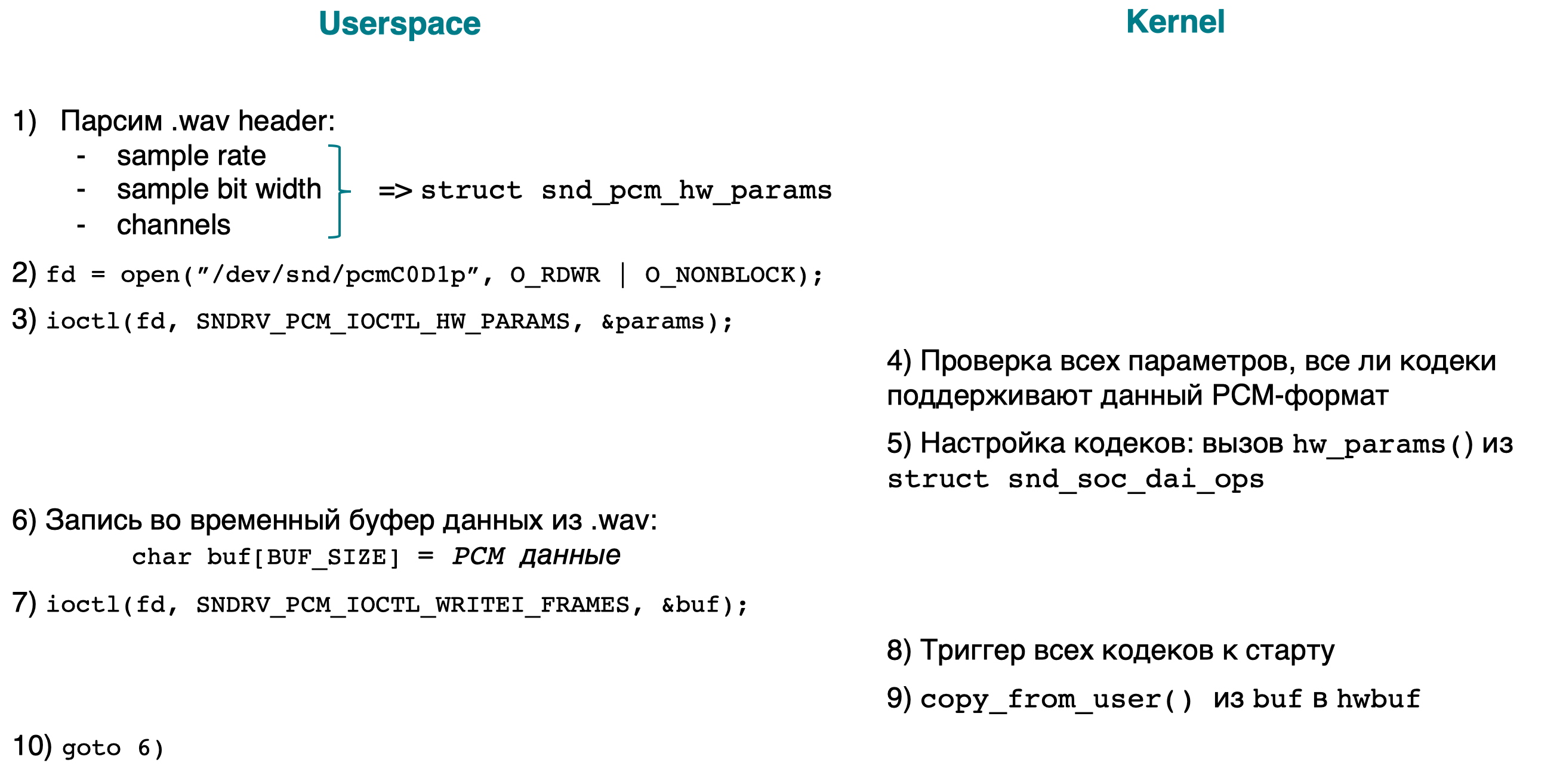
- [userspace] Parse the .wav header to find out the PCM parameters (sample rate, bit width, channels) of the file being played. We add all the parameters to struct snd_pcm_hw_params.
- [userspace] Open the device / dev / snd / pcmC0D0p.
- [userspace] ioctl(…, SNDRV_PCM_IOCTL_HW_PARAMS ,…), PCM- .
- [kernel] PCM-, . :
- ;
- .
- , /dev/snd/pcmC0D0p ( ), .
- [userspace] , PCM-.
- [userspace] ioctl(…, SNDRV_PCM_IOCTL_WRITEI_FRAMES, …). I WRITEI , PCM- interleaved-.
- [kernelspace] , /dev/snd/pcmC0D0p , .
- [kernelspace] copy the user buf to hwbuf (see General Scheme) using copy_from_user ().
- [userspace] goto 6.
The implementation of the kernel part of ioctl can be viewed by searching for the word SNDRV_PCM_IOCTL_ *
Conclusion
We now have an idea of where the sound goes in the Linux kernel. In the following articles, there will be an analysis of how sound is played from Android applications, and for this it has a long way to go.