Unfortunately, I could not find a better quality free model, but I still express my gratitude to the overseas sculptor who captured me in digital! And as you might have guessed, we will talk about writing a CPU - render.
Idea
With the development of shader languages and the increase in GPU power, more and more people are interested in graphics programming. New directions have appeared, such as Ray marching with a rapid growth in its popularity.
In anticipation of the release of a new monster from NVidia, I decided to write my own (tube and old-school) article about the basics of rendering on a CPU. It is a reflection of my personal experience of writing a render, and in it I will try to convey the concepts and algorithms that I encountered in the coding process. It should be understood that the performance of this software will be very low due to the unsuitability of the processor for performing such tasks.
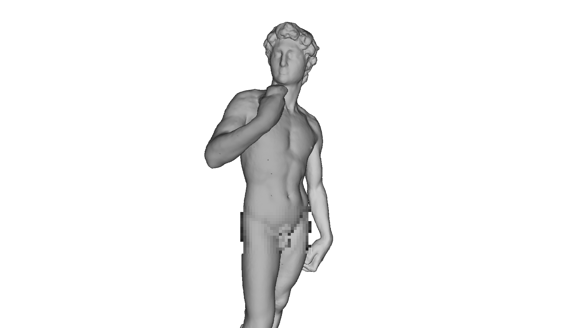
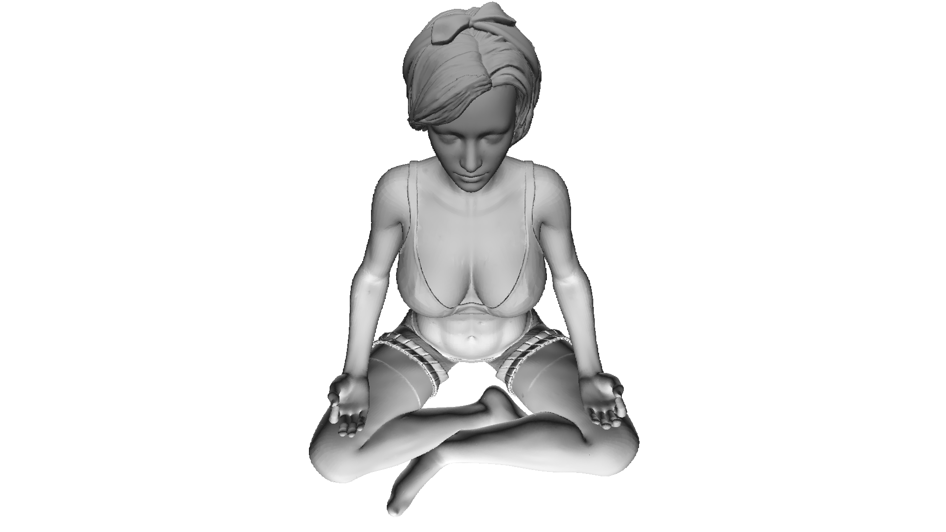
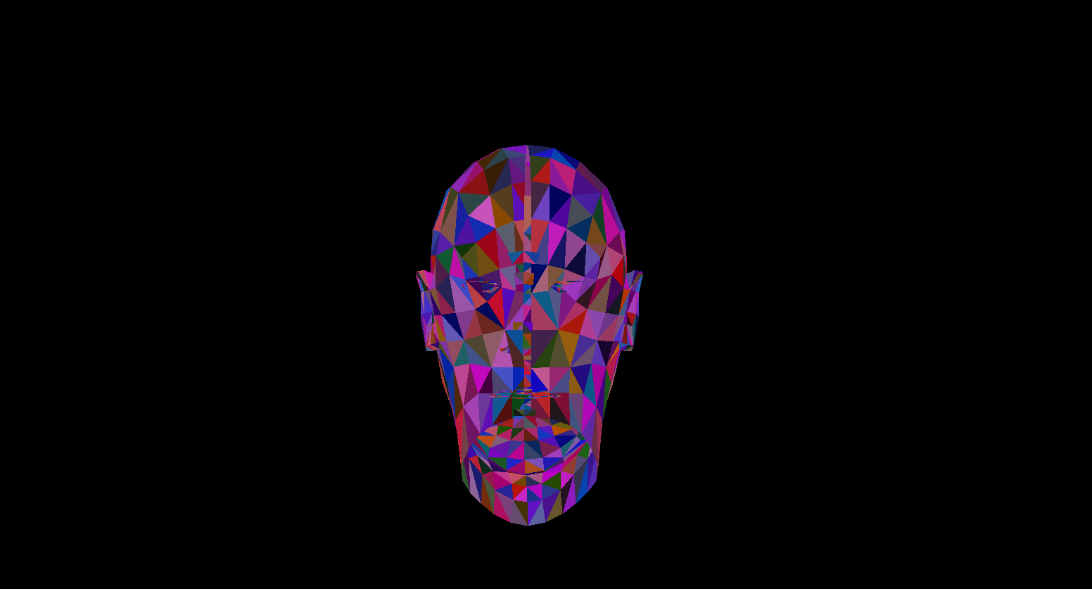
The choice of language initially fell to c ++ or rust , but I settled on c #due to the ease of writing the code and ample opportunities for optimization. The final product of this article will be a render capable of producing images like this:

All the models I used here are distributed in the public domain, do not pirate and respect the work of artists!
Maths
It goes without saying where to write renders without understanding their mathematical foundations. In this section, I will cover only the concepts that I used in the code. I do not advise those who are not sure of their knowledge to skip this section, without understanding these basics it will be difficult to understand the further presentation. I also expect that the one who decided to study computation geometry will have basic knowledge in linear algebra, geometry, as well as trigonometry (angles, vectors, matrices, dot product). For those who want to understand computational geometry more deeply, I can recommend the book by E. Nikulin "Computer Geometry and Computer Graphics Algorithms" .
Vector turns. Rotation matrix
Rotation is one of the basic linear transformations of vector space. It is also an orthogonal transformation, since it preserves the lengths of the transformed vectors. There are two types of rotations in 2D space:
- Rotation relative to the origin
- Rotation about some point
Here I will consider only the first type, since the second is a derivative of the first and differs only in the change of the rotation coordinate system (we will analyze the coordinate system further).
Let's derive formulas for rotating a vector in two-dimensional space. Let's denote the coordinates of the original vector - {x, y} . The coordinates of the new vector, rotated by the angle f , will be denoted as {x 'y'} .
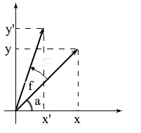
We know that the length of these vectors is common and therefore we can use the concepts of cosine and sine in order to express these vectors in terms of length and angle about the OX axis :

Note that we can use the sum and cosine formulas to expand the x ' and y' values . For those who have forgotten, I will remind these formulas:
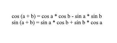
Expanding the coordinates of the rotated vector through them, we get:

It is easy to see here that the factors l * cos a and l * sin a are the coordinates of the original vector: x = l * cos a, y = l * sin a . Let's replace them with x and y :

Thus, we expressed the rotated vector through the coordinates of the original vector and the angle of its rotation. As a matrix, this expression will look like this:
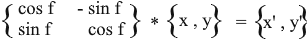
Multiply and check that the result is equivalent to what we deduced.
Rotate in 3D space
We have considered rotation in two-dimensional space, and also derived a matrix for it. Now the question arises, how to get such transformations for three dimensions? In the two-dimensional case, we rotated vectors on a plane, but here there is an infinite number of planes relative to which we can do this. However, there are three basic types of rotations with which you can express any rotation of a vector in three-dimensional space - these are XY , XZ , YZ rotations.
XY rotation.
With this rotation, we rotate the vector about the OZ axis of the coordinate system. Imagine that the vectors are the helicopter blades and the OZ axis is the mast that they hold onto. With XYrotation of the vector will rotate about the OZ axis , like the blades of a helicopter relative to the mast.

Note that with this rotation, the z coordinates of the vectors do not change, but the x and x coordinates change - that's why this is called the XY rotation.
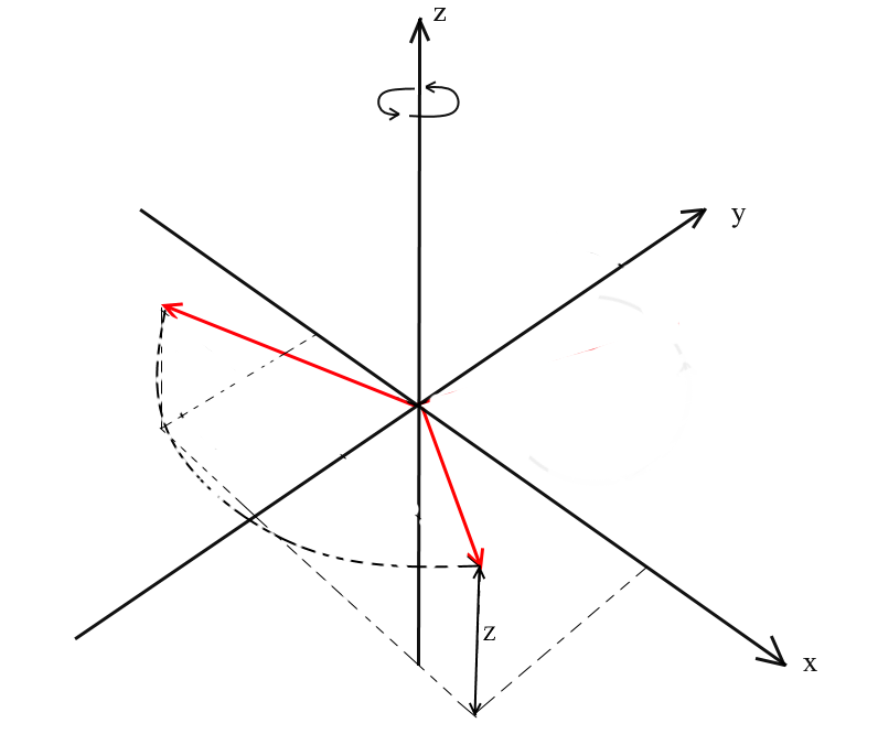
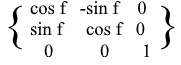
It is not difficult to derive formulas for such a rotation: z - the coordinate remains the same, and x and y change according to the same principles as in 2D rotation.
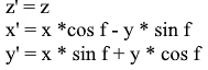
The same in the form of a matrix:
For XZ and YZ rotations, everything is the same:


Projection
The concept of projection can vary depending on the context in which it is used. Many have probably heard of such concepts as projection onto a plane or projection onto a coordinate axis.
In the understanding that we use here, the projection onto a vector is also a vector. Its coordinates are the intersection point of the perpendicular dropped from vector a to b with vector b .
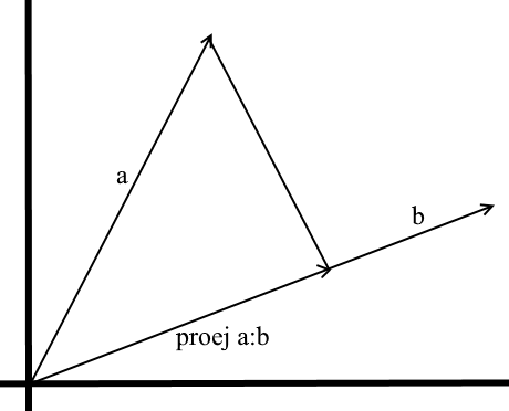
To define such a vector, we need to know its length and direction . As we know, the adjacent leg and the hypotenuse in a right-angled triangle are related by the cosine ratio, so we use it to express the length of the projection vector:
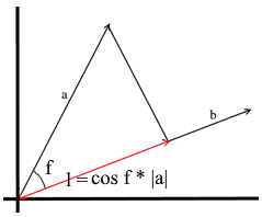
The direction of the projection vector by definition coincides with the vector b , which means the projection is determined by the formula:
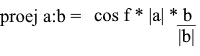
Here we get the direction of the projection as a unit vector and multiply it by the projection length. It is not difficult to understand that the result will be exactly what we are looking for.
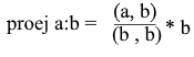
Now let's represent everything in terms of the dot product :

We get a convenient formula for finding the projection:
Coordinate systems. Bases
Many are accustomed to working in the standard XYZ coordinate system , in which any 2 axes will be perpendicular to each other, and the coordinate axes can be represented as unit vectors:

In fact, there are infinitely many coordinate systems, each of them is a basis . The basis of n -dimensional space is a set of vectors {v1, v2 …… vn} through which all vectors of this space are represented. In this case, no vector from the basis can be represented through its other vectors. In fact, each basis is a separate coordinate system in which the vectors will have their own, unique coordinates.
Let's take a look at what a basis for two-dimensional space is. Take, for example, the familiar Cartesian coordinate system of vectors X {1, 0} , Y {0, 1} , which is one of the bases for a two-dimensional space:
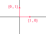
Any vector on a plane can be represented as a sum of vectors of this basis with certain coefficients, or as a linear combination . Remember what you do when you write down the coordinates of a vector - you write x - the coordinate, and then - y . This is how you actually determine the expansion coefficients in terms of the basis vectors.

Now let's take another basis:
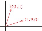
Any 2D vector can also be represented through its vectors:

But such a set of vectors is not the basis of a two-dimensional space:

In it, two vectors {1,1} and {2,2} lie on one straight line. Whatever combinations you take, you will only receive vectors lying on the common straight line y = x . For our purposes, such defective ones will not be useful, however, I think it is worth understanding the difference. By definition, all bases are united by one property - none of the basis vectors can be represented as a sum of other basis vectors with coefficients, or none of the basis vectors is a linear combination of others. Here is an example of a set of 3 vectors that is also not a basis :
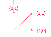
Any vector of a two-dimensional plane can be expressed through it , but the vector {1, 1} in it is superfluous, since it itself can be expressed through the vectors {1, 0} and {0,1} as {1,0} + {0,1 } .
In general, any basis of an n -dimensional space will contain exactly n vectors, for 2e this n is respectively equal to 2.
Let us turn to 3d. The three-dimensional basis will contain 3 vectors:
If for a two-dimensional basis it was enough two vectors not lying on one straight line, then in a three-dimensional space a set of vectors will be a basis if:
- 1) 2 vectors do not lie on one straight line
- 2) the third does not lie on the plane formed by the other two.
From now on, the bases with which we work will be orthogonal (any of their vectors are perpendicular) and normalized (the length of any basis vector is 1). We simply won't need others. For example, the standard basis
meets these criteria.
Transition to another basis
Until now, we have written the decomposition of a vector as a sum of basis vectors with coefficients:

Consider again the standard basis - the vector {1, 3, 6} in it can be written as follows:
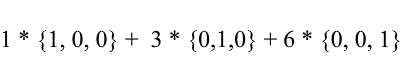
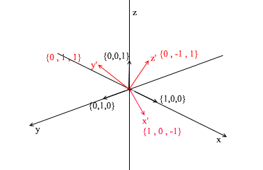
As you can see, the expansion coefficients of a vector in the basis are its coordinates in this basis . Let's look at the following example:
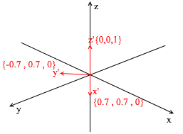
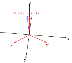
This basis is derived from the standard by applying a 45 degree XY rotation to it . Take a vector a in the standard system with coordinates {0, 1, 1}
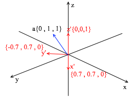
Through the vectors of the new basis, it can be expanded as follows:
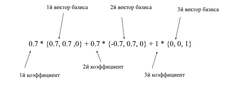
If you calculate this amount, you will get {0, 1, 1} - the vector a in the standard basis. Based on this expression in the new basis the vector a has coordinates {0.7, 0.7, 1} - the expansion coefficients. This will be more visible if you look from a different angle:
But how do you find these coefficients? In general, a universal method is the solution of a rather complex system of linear equations. However, as I said earlier, we will only use orthogonal and normalized bases, and for them there is a very cheating way. It consists in finding projections onto the basis vectors. Let's use it to find the decomposition of the vector a in the basis X {0.7, 0.7, 0} Y {-0.7, 0.7, 0} Z {0, 0, 1}
First, let's find the coefficient for y ' . The first step is to find the projection of the vector a onto the vector y ' (I discussed how to do this above):
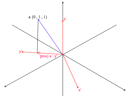
The second step: we divide the length of the found projection by the length of the vector y ' , thereby we find out “how many vectors y' fit in the projection vector” - this number will be the coefficient for y ' , and also y - the coordinate of the vector a in the new basis! For x ' and z', repeat similar operations:

Now we have formulas for the transition from the standard basis to the new one:
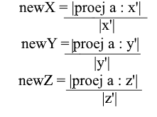
Well, since we use only normalized bases and the lengths of their vectors are equal to 1, there will be no need to divide by the length of the vector in the transition formula:
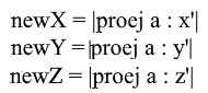
Expand the x- coordinate through the projection formula:

Note that the denominator (x ', x') and the vector x ' in the case of a normalized basis are also 1 and can be discarded. We get:

We see that the x coordinate in the basis is expressed as the dot product (a, x ') , the y coordinate , respectively, as (a, y') , the z coordinate is (a, z ') . Now you can create a matrix of transition to new coordinates:

Offset Coordinate Systems
All coordinate systems that we considered above had the origin of the point {0,0,0} . In addition, there are also systems with a shifted origin point:
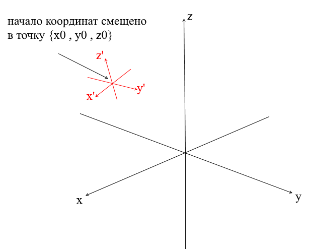
In order to translate a vector into such a system, you must first express it relative to the new center of coordinates. To do this is simple - subtract this center from the vector. Thus, you sort of "move" the coordinate system itself to a new center, while the vector remains in place. Next, you can use the transition matrix already familiar to us.
Writing a geometry engine. Create a wire render.
Well, I think someone who went through the section with mathematics and did not close the article can be brainwashed with more interesting things! In this section, we will start writing the basics of a 3D engine and rendering. In general, rendering is a rather complex procedure that includes many different operations: cutting off invisible edges, rasterizing, calculating light, processing various effects, materials (sometimes even physics). We will partially analyze all this in the future, but now we will do more simple things - we will write a wire render. Its essence is that it draws an object in the form of lines connecting its vertices, so the result looks like a network of wires:
Polygonal graphics
Traditionally, computer graphics use polygonal representations of 3D object data. Thus, data are presented in OBJ, 3DS, FBX and many others. In a computer, such data is stored in the form of two sets: a set of vertices and a set of faces (polygons). Each vertex of an object is represented by its position in space - a vector, and each face (polygon) is represented by three integers that are indices of the vertices of this object. The simplest objects (cubes, spheres, etc.) consist of such polygons and are called primitives.
In our engine, the primitive will be the main object of three-dimensional geometry - all other objects will inherit from it. Let's describe the primitive class:
    abstract class Primitive
    {
        public Vector3[] Vertices { get; protected set; }
        public int[] Indexes { get; protected set; }
    }
So far, everything is simple - there are vertices of the primitive and there are indices for forming polygons. Now you can use this class to create a cube:
   public class Cube : Primitive
      {
        public Cube(Vector3 center, float sideLen)
        {
            var d = sideLen / 2;
            Vertices = new Vector3[]
                {
                    new Vector3(center.X - d , center.Y - d, center.Z - d) ,
                    new Vector3(center.X - d , center.Y - d, center.Z) ,
                    new Vector3(center.X - d , center.Y , center.Z - d) ,
                    new Vector3(center.X - d , center.Y , center.Z) ,
                    new Vector3(center.X + d , center.Y - d, center.Z - d) ,
                    new Vector3(center.X + d , center.Y - d, center.Z) ,
                    new Vector3(center.X + d , center.Y + d, center.Z - d) ,
                    new Vector3(center.X + d , center.Y + d, center.Z + d) ,
                };

            Indexes = new int[]
                {
                    1,2,4 ,
                    1,3,4 ,
                    1,2,6 ,
                    1,5,6 ,
                    5,6,8 ,
                    5,7,8 ,
                    8,4,3 ,
                    8,7,3 ,
                    4,2,8 ,
                    2,8,6 ,
                    3,1,7 ,
                    1,7,5
                };
        }
    }

int Main()
{
        var cube = new Cube(new Vector3(0, 0, 0), 2);
}

Implementing coordinate systems
It is not enough to set an object with a set of polygons; for planning and creating complex scenes, you need to place objects in different places, rotate them, reduce or increase them in size. For the convenience of these operations, the so-called local and global coordinate systems are used. Each object on the scene has its own coordinate system - local, as well as its own center point.
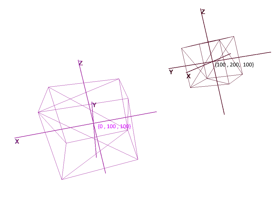
Representation of an object in local coordinates allows you to easily perform any operations with it. For example, to move an object by vector a , it will be enough to shift the center of its coordinate system by this vector, to rotate an object - rotate its local coordinates.
When working with an object, we will perform operations with its vertices in the local coordinate system; during rendering, we will first translate all objects in the scene into a single coordinate system - the global one. Let's add coordinate systems to the code. To do this, create an object of the Pivot class (pivot, pivot point) that will represent the local basis of the object and its center point. Converting a point to the coordinate system provided by Pivot will be done in 2 steps:
- 1) Representation of a point relative to the center of new coordinates
- 2) Expansion in vectors of the new basis
On the contrary, in order to represent the local vertex of an object in global coordinates, you must perform these actions in reverse order:
- 1) Expansion in vectors of the global basis
- 2) Representation relative to the global center
Let's write a class to represent coordinate systems:
    public class Pivot
    {
        //
        public Vector3 Center { get; private set; }
        //   -
        public Vector3 XAxis { get; private set; }
        public Vector3 YAxis { get; private set; }
        public Vector3 ZAxis { get; private set; }

        //
        public Matrix3x3 LocalCoordsMatrix => new Matrix3x3
            (
                XAxis.X, YAxis.X, ZAxis.X,
                XAxis.Y, YAxis.Y, ZAxis.Y,
                XAxis.Z, YAxis.Z, ZAxis.Z
            );

        //
        public Matrix3x3 GlobalCoordsMatrix => new Matrix3x3
            (
                XAxis.X , XAxis.Y , XAxis.Z,
                YAxis.X , YAxis.Y , YAxis.Z,
                ZAxis.X , ZAxis.Y , ZAxis.Z
            );

        public Vector3 ToLocalCoords(Vector3 global)
        {
            //
            return LocalCoordsMatrix * (global - Center);
        }
        public Vector3 ToGlobalCoords(Vector3 local)
        {
            //    -
            return (GlobalCoordsMatrix * local)  + Center;
        }

        public void Move(Vector3 v)
        {
            Center += v;
        }

        public void Rotate(float angle, Axis axis)
        {
            XAxis = XAxis.Rotate(angle, axis);
            YAxis = YAxis.Rotate(angle, axis);
            ZAxis = ZAxis.Rotate(angle, axis);
        }
    }
Now, using this class, add the functions of rotation, movement and increase to the primitives:
    public abstract class Primitive
    {
        //
        public Pivot Pivot { get; protected set; }
        //
        public Vector3[] LocalVertices { get; protected set; }
        //
        public Vector3[] GlobalVertices { get; protected set; }
        //
        public int[] Indexes { get; protected set; }

        public void Move(Vector3 v)
        {
            Pivot.Move(v);

            for (int i = 0; i < LocalVertices.Length; i++)
                GlobalVertices[i] += v;
        }

        public void Rotate(float angle, Axis axis)
        {
            Pivot.Rotate(angle , axis);

            for (int i = 0; i < LocalVertices.Length; i++)
                GlobalVertices[i] = Pivot.ToGlobalCoords(LocalVertices[i]);
        }

        public void Scale(float k)
        {
            for (int i = 0; i < LocalVertices.Length; i++)
                LocalVertices[i] *= k;

            for (int i = 0; i < LocalVertices.Length; i++)
                GlobalVertices[i] = Pivot.ToGlobalCoords(LocalVertices[i]);
        }
    }
Rotating and Moving an Object Using Local Coordinates
Drawing polygons. Camera
The main object of the scene will be the camera - with the help of it the objects will be drawn on the screen. The camera, like all objects in the scene, will have local coordinates in the form of an object of the Pivot class - through it we will move and rotate the camera:

To display the object on the screen, we will use a simple perspective projection method . The principle on which this method is based is that the further from us the object is, the smaller it will seem. Probably many people once solved the problem at school about measuring the height of a tree located at a certain distance from the observer:
Imagine that a ray from the top point of a tree falls on a certain projection plane located at a distance C1 from the observer and draws a point on it. The observer sees this point and wants to determine the height of the tree from it. As you can see, the height of the tree and the height of a point on the projection plane are related by the ratio of similar triangles. Then the observer can determine the height of the point using this ratio:
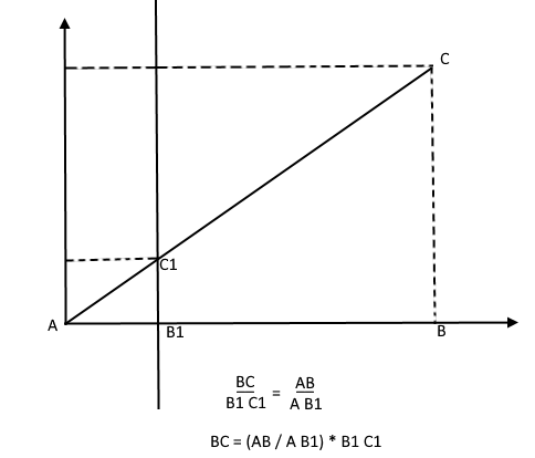
On the contrary, knowing the height of the tree, he can find the height of a point on the projection plane:
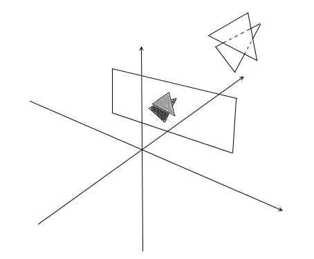
Now let's go back to our camera. Imagine that a projection plane is attached to the z- axis of the camera coordinates at a distance z ' from the origin. The formula for such a plane is z = z ' , it can be given by one number - z' . Rays from the vertices of various objects fall on this plane. When the ray hits the plane, it will leave a point on it. By connecting such points, you can draw an object.

This plane will represent the screen. We will find the coordinate of the projection of the vertex of the object on the screen in 2 stages:
- 1) We translate the vertex into the local coordinates of the camera
- 2) Find the projection of a point through the ratio of similar triangles

The projection will be a 2-dimensional vector, its x 'and y' coordinates will define the position of the point on the computer screen.
Chamber class 1
public class Camera
{
    //
    public Pivot Pivot { get; private set; }
    //
    public float ScreenDist { get; private set; }

    public Camera(Vector3 center, float screenDist)
    {
        Pivot = new Pivot(center);
        ScreenDist = screenDist;
    }
    public void Move(Vector3 v)
    {
        Pivot.Move(v);
    }
    public void Rotate(float angle, Axis axis)
    {
        Pivot.Rotate(angle, axis);
    }
    public Vector2 ScreenProection(Vector3 v)
    {
        var local = Pivot.ToLocalCoords(v);
        //
        var delta = ScreenDist / local.Z;
        var proection = new Vector2(local.X, local.Y) * delta;
        return proection;
    }
}
This code has several errors, which we will talk about fixing later.
Cut off invisible polygons
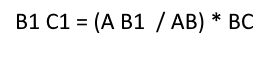
Having projected three points of the polygon on the screen in this way, we get the coordinates of the triangle which corresponds to the display of the polygon on the screen. But in this way the camera will process any vertices, including those whose projections go beyond the screen area, if you try to draw such a vertex, there is a high probability of catching errors. The camera will also process the polygons that are behind it (the z coordinates of their points in the local camera baseline are less than z ' ) - we also don't need such "occipital" vision.
For clipping invisible vertices in open gl, the truncation pyramid method is used. It consists in setting two planes - near (near plane) and far (far plane). Everything that lies between these two planes will be subject to further processing. I use a simplified version with one clipping plane - z ' . All vertices behind it will be invisible.
Let's add two new fields to the camera - screen width and height.
Now we will check each projected point for hitting the screen area. Let's also cut off the points behind the camera. If the point lies behind or its projection does not fall on the screen, then the method will return point {float.NaN, float.NaN} .
Camera code 2
public Vector2 ScreenProection(Vector3 v)
{
    var local = Pivot.ToLocalCoords(v);
    //
    if (local.Z < ScreenDist)
    {
        return new Vector2(float.NaN, float.NaN);
    }
    //
    var delta = ScreenDist / local.Z;
    var proection = new Vector2(local.X, local.Y) * delta;
    //     -
    if (proection.X >= 0 && proection.X < ScreenWidth && proection.Y >= 0 && proection.Y < ScreenHeight)
    {
        return proection;
    }
    return new Vector2(float.NaN, float.NaN);
}
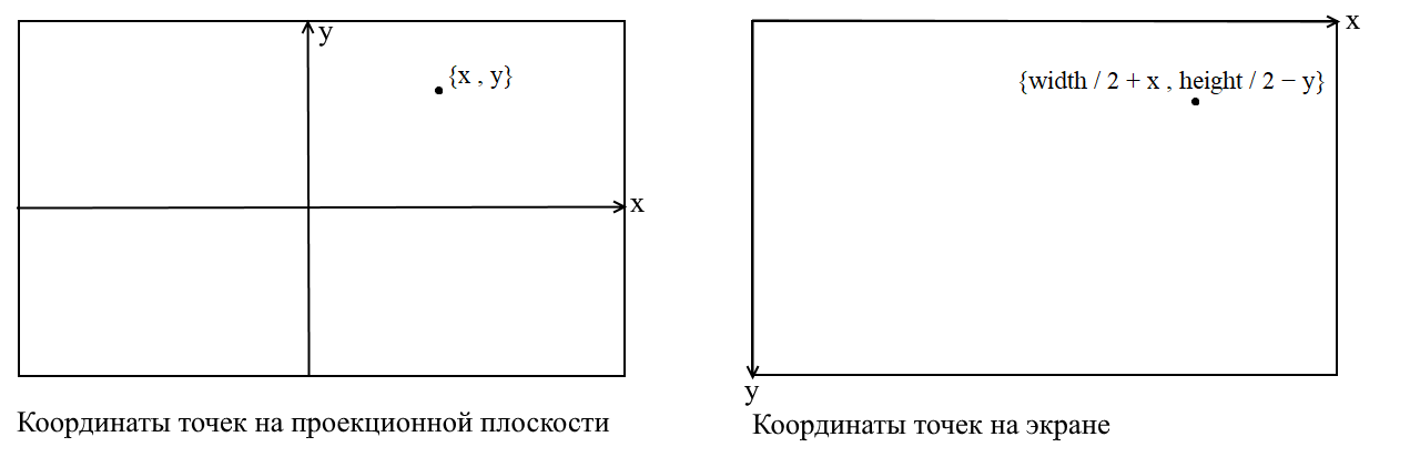
Translating to screen coordinates
Here I will clarify a point. It is connected with the fact that in many graphic libraries drawing occurs in the screen coordinate system, in such coordinates the origin is the upper left point of the screen, x increases when moving to the right, and y when moving down. In our projection plane, points are represented in ordinary Cartesian coordinates, and before drawing, these coordinates must be converted to screen coordinates. This is not difficult to do, you just need to shift the origin to the upper left corner and invert y :
Camera code 3
public Vector2 ScreenProection(Vector3 v)
{
    var local = Pivot.ToLocalCoords(v);
    //
    if (local.Z < ScreenDist)
    {
        return new Vector2(float.NaN, float.NaN);
    }
    //
    var delta = ScreenDist / local.Z;
    var proection = new Vector2(local.X, local.Y) * delta;
    //
    var screen = proection + new Vector2(ScreenWidth / 2, -ScreenHeight / 2);
    var screenCoords = new Vector2(screen.X, -screen.Y);
    //     -
    if (screenCoords.X >= 0 && screenCoords.X < ScreenWidth && screenCoords.Y >= 0 && screenCoords.Y < ScreenHeight)
    {
        return screenCoords;
    }
    return new Vector2(float.NaN, float.NaN);
}
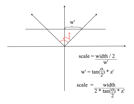
Adjusting the size of the projected image
If you use the previous code to draw an object you will get something like this:

For some reason, all objects are drawn very small. In order to understand the reason, remember how we calculated the projection - we multiplied the x and y coordinates by the delta of the z '/ z ratio . This means that the size of the object on the screen depends on the distance to the projection plane z ' . But we can set z ' as small as we want. This means we need to adjust the projection size depending on the current z ' value . To do this, let's add another field to the camera - its angle of view .

We need it to match the angular size of the screen with its width. The angle will be matched to the width of the screen in this way: the maximum angle within which the camera is looking is the left or right edge of the screen. Then the maximum angle from the z- axis of the camera is o / 2 . The projection that hit the right edge of the screen should have the x = width / 2 coordinate , and the left one: x = -width / 2 . Knowing this, we derive the formula for finding the projection stretch coefficient:
Camera code 4
public float ObserveRange { get; private set; }
public float Scale => ScreenWidth / (float)(2 * ScreenDist * Math.Tan(ObserveRange / 2));
public Vector2 ScreenProection(Vector3 v)
{
    var local = Pivot.ToLocalCoords(v);
    //
    if (local.Z < ScreenDist)
    {
        return new Vector2(float.NaN, float.NaN);
    }
    //
    var delta = ScreenDist / local.Z * Scale;
    var proection = new Vector2(local.X, local.Y) * delta;
    //
    var screen = proection + new Vector2(ScreenWidth / 2, -ScreenHeight / 2);
    var screenCoords = new Vector2(screen.X, -screen.Y);
    //     -
    if (screenCoords.X >= 0 && screenCoords.X < ScreenWidth && screenCoords.Y >= 0 && screenCoords.Y < ScreenHeight)
    {
        return screenCoords;
    }
    return new Vector2(float.NaN, float.NaN);
}
Here's a simple rendering code I used for the test:
Object drawing code
public DrawObject(Primitive primitive , Camera camera)
{
    for (int i = 0; i < primitive.Indexes.Length; i+=3)
    {
        var color = randomColor();
        //
        var i1 = primitive.Indexes[i];
        var i2 = primitive.Indexes[i+ 1];
        var i3 = primitive.Indexes[i+ 2];
        //
        var v1 = primitive.GlobalVertices[i1];
        var v2 = primitive.GlobalVertices[i2];
        var v3 = primitive.GlobalVertices[i3];
        //
        DrawPolygon(v1,v2,v3 , camera , color);
    }
}

public void DrawPolygon(Vector3 v1, Vector3 v2, Vector3 v3, Camera camera , color)
{
    //
    var p1 = camera.ScreenProection(v1);
    var p2 = camera.ScreenProection(v2);
    var p3 = camera.ScreenProection(v3);
    //
    DrawLine(p1, p2 , color);
    DrawLine(p2, p3 , color);
    DrawLine(p3, p2 , color);
}
Let's check the render on the scene and cubes:
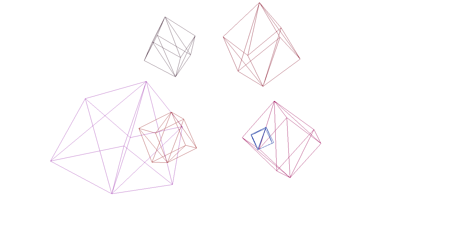
And yes, everything works great. For those who do not find colorful cubes pretentious, I wrote a function for parsing OBJ format models into Primitive objects, filled the background with black and rendered several models:
The result of the render

Rasterization of polygons. We bring beauty.
In the last section, we wrote a wireframe render. Now we will deal with its modernization - we will implement the rasterization of polygons.
Simply rasterizing a polygon means painting over it. It would seem why write a bicycle when there are already ready-made triangle rasterization functions. Here's what happens if you draw everything with the default tools:
Contemporary art, polygons behind the front ones were drawn, in a word - porridge. Also, how do you texture objects in this way? Yes, no way. So we need to write our own imba rasterizer, which will be able to cut off invisible points , textures, and even shaders! But in order to do this, it is worth understanding how to paint triangles in general.
Bresenham's Algorithm for Line Drawing.
Let's start with the lines. If anyone did not know the Bresenham algorithm, this is the main algorithm for drawing straight lines in computer graphics. He or its modifications are used literally everywhere: drawing lines, segments, circles, etc. Anyone interested in a more detailed description - read the wiki. Bresenham's algorithm
There is a line segment connecting the points {x1, y1} and {x2, y2} . To draw a segment between them, you need to paint over all the pixels that fall on it. For two points of the segment, you can find the x- coordinates of the pixels in which they lie: you just need to take whole parts of the coordinates x1 and x2 . To paint pixels on a segment, start a cycle from x1 to x2 and at each iteration calculatey - coordinate of the pixel that falls on the line. Here is the code:
void Brezenkhem(Vector2 p1 , Vector2 p2)
{
    int x1 = Floor(p1.X);
    int x2 = Floor(p2.X);
    if (x1 > x2) {Swap(x1, x2); Swap(p1 , p2);}
    float d = (p2.Y - p1.Y) / (x2 - x1);
    float y = p1.Y;
    for (int i = x1; i <= x2; i++)
    {
        int pixelY = Floor(y);
        FillPixel(i , pixelY);
        y += d;
    }
}

Picture from wiki
Rasterize a triangle. Fill Algorithm
We know how to draw lines, but with triangles it will be a little more difficult (not much)! The task of drawing a triangle is reduced to several tasks of drawing lines. First, let's split the triangle into two parts, having previously sorted the points in ascending order x :
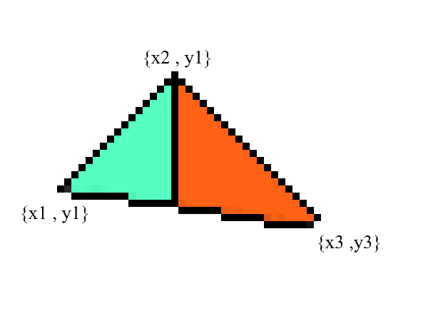
Notice - now we have two parts in which the lower and upper borders are clearly expressed . all that remains is to fill in all the pixels in between! This can be done in 2 cycles: from x1 to x2 and from x3 to x2 .
void Triangle(Vector2 v1 , Vector2 v2 , Vector2 v3)
{
    // BubbleSort    x
    if (v1.X > v2.X) { Swap(v1, v2); }
    if (v2.X > v3.X) { Swap(v2, v3); }
    if (v1.X > v2.X) { Swap(v1, v2); }

    //    y    x
    //   0:  x1 == x2     -
    var steps12 = max(v2.X - v1.X , 1);
    var steps13 = max(v3.X - v1.X , 1);
    var upDelta = (v2.Y - v1.Y) / steps12;
    var downDelta = (v3.Y - v1.Y) / steps13;

    //
    if (upDelta < downDelta) Swap(upDelta , downDelta);

    //     y1
    var up = v1.Y;
    var down = v1.Y;

    for (int i = (int)v1.X; i <= (int)v2.X; i++)
    {
        for (int g = (int)down; g <= (int)up; g++)
        {
            FillPixel(i , g);
        }
        up += upDelta;
        down += downDelta;
    }

    //
    var steps32 = max(v2.X - v3.X , 1);
    var steps31 = max(v1.X - v3.X , 1);
    upDelta = (v2.Y - v3.Y) / steps32;
    downDelta = (v1.Y - v3.Y) / steps31;

    if (upDelta < downDelta) Swap(upDelta, downDelta);

    up = v3.Y;
    down = v3.Y;

    for (int i = (int)v3.X; i >=(int)v2.X; i--)
    {
        for (int g = (int)down; g <= (int)up; g++)
        {
            FillPixel(i, g);
        }
        up += upDelta;
        down += downDelta;
    }
}
Undoubtedly, this code can be refactored and not to duplicate the loop:
void Triangle(Vector2 v1 , Vector2 v2 , Vector2 v3)
{
    if (v1.X > v2.X) { Swap(v1, v2); }
    if (v2.X > v3.X) { Swap(v2, v3); }
    if (v1.X > v2.X) { Swap(v1, v2); }

    var steps12 = max(v2.X - v1.X , 1);
    var steps13 = max(v3.X - v1.X , 1);
    var steps32 = max(v2.X - v3.X , 1);
    var steps31 = max(v1.X - v3.X , 1);

    var upDelta = (v2.Y - v1.Y) / steps12;
    var downDelta = (v3.Y - v1.Y) / steps13;
    if (upDelta < downDelta) Swap(upDelta , downDelta);

    TrianglePart(v1.X , v2.X , v1.Y , upDelta , downDelta);

    upDelta = (v2.Y - v3.Y) / steps32;
    downDelta = (v1.Y - v3.Y) / steps31;
    if (upDelta < downDelta) Swap(upDelta, downDelta);

    TrianglePart(v3.X, v2.X, v3.Y, upDelta, downDelta);
}

void TrianglePart(float x1 , float x2 , float y1  , float upDelta , float downDelta)
{
    float up = y1, down = y1;
    for (int i = (int)x1; i <= (int)x2; i++)
    {
        for (int g = (int)down; g <= (int)up; g++)
        {
            FillPixel(i , g);
        }
        up += upDelta; down += downDelta;
    }
}
Clipping invisible points.
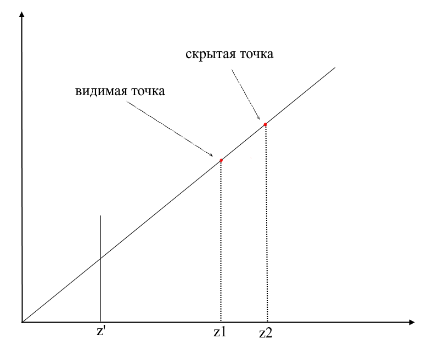
First, think about how you see. Now there is a screen in front of you, and what is behind it is hidden from your eyes. In rendering, a similar mechanism works - if one polygon overlaps another, the render will draw it over the overlapped one. On the contrary, it will not draw the closed part of the polygon:
In order to understand whether the points are visible or not, the zbuffer mechanism (depth buffer) is used in rendering . zbuffer can be thought of as a two-dimensional array (can be compressed into one-dimensional) with width * height . For each pixel on the screen, it stores a z - value - the coordinates on the original polygon from where this point was projected. Accordingly, the closer the point is to the observer, the smaller its z -coordinate. Ultimately, if the projections of several points coincide, you need to rasterize the point with the minimum z - coordinate :
Now the question arises - how to find the z- coordinates of points on the original polygon? This can be done in several ways. For example, you can shoot a ray from the origin of the camera, passing through a point on the projection plane {x, y, z '} and find its intersection with the polygon. But looking for intersections is an extremely expensive operation, so we will use a different method. To draw a triangle, we interpolated the coordinates of its projections , now, in addition to this, we will also interpolate the coordinates of the original polygon . To cut off invisible points, we will use the zbuffer state for the current frame in the rasterization method .
My zbuffer will look likeVector3 [] - it will contain not only z - coordinates , but also interpolated values of polygon points (fragments) for each screen pixel. This is done in order to save memory, since in the future we will still need these values for writing shaders ! In the meantime, we have the following code to determine the visible vertices (fragments) :
The code
public void ComputePoly(Vector3 v1, Vector3 v2, Vector3 v3 , Vector3[] zbuffer)
{
    //
    var v1p = Camera.ScreenProection(v1);
    var v2p = Camera.ScreenProection(v2);
    var v3p = Camera.ScreenProection(v3);

    //   x -
    //,     -
    if (v1p.X > v2p.X) { Swap(v1p, v2p); Swap(v1p, v2p); }
    if (v2p.X > v3p.X) { Swap(v2p, v3p); Swap(v2p, v3p); }
    if (v1p.X > v2p.X) { Swap(v1p, v2p); Swap(v1p, v2p); }

    //
    int x12 = Math.Max((int)v2p.X - (int)v1p.X, 1);
    int x13 = Math.Max((int)v3p.X - (int)v1p.X, 1);

    //
    float dy12 = (v2p.Y - v1p.Y) / x12; var dr12 = (v2 - v1) / x12;
    float dy13 = (v3p.Y - v1p.Y) / x13; var dr13 = (v3 - v1) / x13;

    Vector3 deltaUp, deltaDown; float deltaUpY, deltaDownY;
    if (dy12 > dy13) { deltaUp = dr12; deltaDown = dr13; deltaUpY = dy12; deltaDownY = dy13;}
    else { deltaUp = dr13; deltaDown = dr12; deltaUpY = dy13; deltaDownY = dy12;}

    TrianglePart(v1 , deltaUp , deltaDown , x12 , 1 , v1p , deltaUpY , deltaDownY , zbuffer);
    //    -
}
public void ComputePolyPart(Vector3 start, Vector3 deltaUp, Vector3 deltaDown,
    int xSteps, int xDir, Vector2 pixelStart, float deltaUpPixel, float deltaDownPixel , Vector3[] zbuffer)
{
    int pixelStartX = (int)pixelStart.X;
    Vector3 up = start - deltaUp, down = start - deltaDown;
    float pixelUp = pixelStart.Y - deltaUpPixel, pixelDown = pixelStart.Y - deltaDownPixel;
    for (int i = 0; i <= xSteps; i++)
    {
        up += deltaUp; pixelUp += deltaUpPixel;
        down += deltaDown; pixelDown += deltaDownPixel;
        int steps = ((int)pixelUp - (int)pixelDown);
        var delta = steps == 0 ? Vector3.Zero : (up - down) / steps;
        Vector3 position = down - delta;
        for (int g = 0; g <= steps; g++)
        {
            position += delta;
            var proection = new Point(pixelStartX + i * xDir, (int)pixelDown + g);
            int index = proection.Y * Width + proection.X;
            //
            if (zbuffer[index].Z == 0 || zbuffer[index].Z > position.Z)
            {
                zbuffer[index] = position;
            }
        }
    }
}
Animation of rasterizer steps (when rewriting the depth in zbuffer, the pixel is highlighted in red):
For convenience, I moved all the code into a separate Rasterizer module:
Rasterizer class
    public class Rasterizer
    {
        public Vertex[] ZBuffer;
        public int[] VisibleIndexes;
        public int VisibleCount;
        public int Width;
        public int Height;
        public Camera Camera;

        public Rasterizer(Camera camera)
        {
            Shaders = shaders;
            Width = camera.ScreenWidth;
            Height = camera.ScreenHeight;
            Camera = camera;

        }
        public Bitmap Rasterize(IEnumerable<Primitive> primitives)
        {
            var buffer = new Bitmap(Width , Height);
            ComputeVisibleVertices(primitives);
            for (int i = 0; i < VisibleCount; i++)
            {
                var vec = ZBuffer[index];
                var proec = Camera.ScreenProection(vec);
                buffer.SetPixel(proec.X , proec.Y);
            }
            return buffer.Bitmap;
        }
        public void ComputeVisibleVertices(IEnumerable<Primitive> primitives)
        {
            VisibleCount = 0;
            VisibleIndexes = new int[Width * Height];
            ZBuffer = new Vertex[Width * Height];
            foreach (var prim in primitives)
            {
                foreach (var poly in prim.GetPolys())
                {
                    MakeLocal(poly);
                    ComputePoly(poly.Item1, poly.Item2, poly.Item3);
                }
            }
        }
        public void MakeLocal(Poly poly)
        {
            poly.Item1.Position = Camera.Pivot.ToLocalCoords(poly.Item1.Position);
            poly.Item2.Position = Camera.Pivot.ToLocalCoords(poly.Item2.Position);
            poly.Item3.Position = Camera.Pivot.ToLocalCoords(poly.Item3.Position);

        }
    }
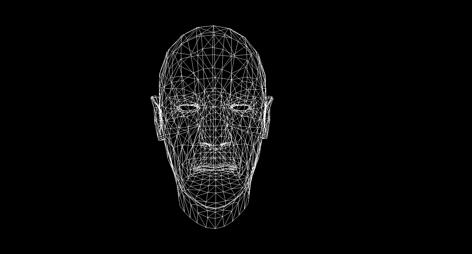
Now let's check the render work. For this I use Sylvanas' model from the famous RPG "WOW":

Not very clear, right? This is because there are no textures or lighting here. But we'll fix it soon.
Textures! Normal! Lighting! Motor!
Why did I combine it all into one section? And because in essence texturization and calculation of normals are absolutely identical and you will soon understand this.
First, let's look at the texturing task for one polygon. Now, in addition to the usual coordinates of the vertices of the polygon, we will also store its texture coordinates . The texture coordinate of the vertex is represented as a 2D vector and points to a pixel in the texture image. I found a good picture on the internet to show this:
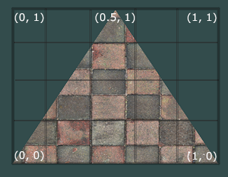
Note that the beginning of the texture ( bottom left pixel ) in texture coordinates is {0, 0} , and the end ( top right pixel ) is {1, 1} . Take into account the texture coordinate system and the possibility of going beyond the borders of the image when the texture coordinate is 1.
Let's create a class to represent the vertex data right away:
  public class Vertex
    {
        public Vector3 Position { get; set; }
        public Color Color { get; set; }
        public Vector2 TextureCoord { get; set; }
        public Vector3 Normal { get; set; }

        public Vertex(Vector3 pos , Color color , Vector2 texCoord , Vector3 normal)
        {
            Position = pos;
            Color = color;
            TextureCoord = texCoord;
            Normal = normal;
        }
    }
I will explain why normals are needed later, for now we'll just know that vertices can have them. Now, to texturize the polygon, we need to somehow map the color value from the texture to a specific pixel. Remember how we interpolated the vertices? Do the same here! I will not rewrite the rasterization code again, but I suggest you implement texturing in your render yourself. The result should be the correct display of textures on the model. Here's what I got:
textured model
All information about the texture coordinates of the model is in the OBJ file. To use this learn the format: OBJ format.
Lighting
With textures everything has become much more fun, but the real fun will be when we implement lighting for the scene. To simulate "cheap" lighting, I will use the Phong model .
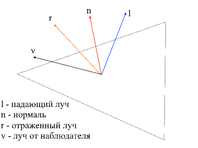
Phong model
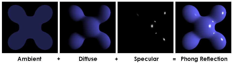
In general, this method simulates the presence of 3 components of lighting: the background (ambient), scattered (diffuse) and mirror (reflect). The sum of these three components will eventually simulate the physical behavior of light.
Phong Model
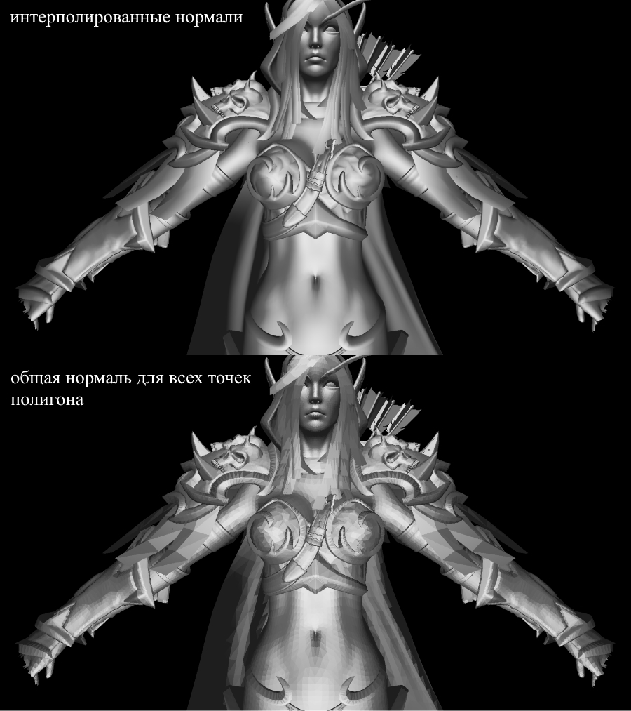
To calculate the Phong lighting we needsurface normals , for this I added them in the Vertex class. Where can we get the values of these normals? No, we don't need to calculate anything. The fact is that generous 3D editors often consider them themselves and provide models along with the data in the context of the OBJ format. Having parsed the model file we get the normal value for 3 vertices of each polygon.
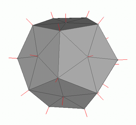
Picture from wiki
In order to calculate the normal at each point on the polygon, you need to interpolate these values, we already know how to do this. Now let's take a look at all the components for calculating the Phong lighting.
Background light (Ambient)
Initially, we set the constant background lighting , for non-textured objects, you can choose any color for objects with textures I divide each of the RGB components at a ratio of basic shading (baseShading).
Diffuse light
When light hits the surface of the polygon, it is evenly scattered. To calculate the diffuse value for a specific pixel, the angle at which the light hits the surface is taken into account . To calculate this angle, you can apply the dot product of the incident ray and the normal (of course, the vectors must be normalized before that). This angle will be multiplied by a factor of light intensity. If the dot product is negative, it means that the angle between the vectors is greater than 90 degrees. In this case, we will begin to calculate not lightening, but, on the contrary, shading. It is worth avoiding this point, you can do it using the max function .
The code
public interface IShader
    {
        void ComputeShader(Vertex vertex, Camera camera);
    }

    public struct Light
    {
        public Vector3 Pos;
        public float Intensivity;
    }

public class PhongModelShader : IShader
    {
        public static float DiffuseCoef = 0.1f;
        public Light[] Lights { get; set; }

        public PhongModelShader(params Light[] lights)
        {
            Lights = lights;
        }
        public void ComputeShader(Vertex vertex, Camera camera)
        {
            if (vertex.Normal.X == 0 && vertex.Normal.Y == 0 && vertex.Normal.Z == 0)
            {
                return;
            }
            var gPos = camera.Pivot.ToGlobalCoords(vertex.Position);
            foreach (var light in Lights)
            {
                var ldir = Vector3.Normalize(light.Pos - gPos);
                var diffuseVal = Math.Max(VectorMath.Cross(ldir, vertex.Normal), 0) * light.Intensivity;
                vertex.Color = Color.FromArgb(vertex.Color.A,
                    (int)Math.Min(255, vertex.Color.R * diffuseVal * DiffuseCoef),
                    (int)Math.Min(255, vertex.Color.G * diffuseVal * DiffuseCoef,
                    (int)Math.Min(255, vertex.Color.B * diffuseVal * DiffuseCoef));
            }
        }
    }
Let's apply diffused light and dispel the darkness:

Mirror light (Reflect)
To calculate the mirror component, you need to take into account the point from which we look at the object . Now we will take the dot product of the ray from the observer and the ray reflected from the surface multiplied by the light intensity factor.
It is easy to find the ray from the observer to the surface - it will be just the position of the processed vertex in local coordinates . In order to find the reflected ray, I used the following method. The incident ray can be decomposed into 2 vectors: its projection onto the normal and the second vector, which can be found by subtracting this projection from the incident ray. To find the reflected ray, you need to subtract the value of the second vector from the projection onto the normal.
the code
    public class PhongModelShader : IShader
    {
        public static float DiffuseCoef = 0.1f;
        public static float ReflectCoef = 0.2f;
        public Light[] Lights { get; set; }

        public PhongModelShader(params Light[] lights)
        {
            Lights = lights;
        }
        public void ComputeShader(Vertex vertex, Camera camera)
        {
            if (vertex.Normal.X == 0 && vertex.Normal.Y == 0 && vertex.Normal.Z == 0)
            {
                return;
            }
            var gPos = camera.Pivot.ToGlobalCoords(vertex.Position);
            foreach (var light in Lights)
            {
                var ldir = Vector3.Normalize(light.Pos - gPos);
                //
                var proection = VectorMath.Proection(ldir, -vertex.Normal);
                var d = ldir - proection;
                var reflect = proection - d;
                var diffuseVal = Math.Max(VectorMath.Cross(ldir, -vertex.Normal), 0) * light.Intensivity;
                //
                var eye = Vector3.Normalize(-vertex.Position);
                var reflectVal = Math.Max(VectorMath.Cross(reflect, eye), 0) * light.Intensivity;
                var total = diffuseVal * DiffuseCoef + reflectVal * ReflectCoef;
                vertex.Color = Color.FromArgb(vertex.Color.A,
                    (int)Math.Min(255, vertex.Color.R * total),
                    (int)Math.Min(255, vertex.Color.G * total),
                    (int)Math.Min(255, vertex.Color.B * total));
            }
        }
    }
Now the picture looks like this:

Shadows
The end point of my presentation will be the implementation of shadows for rendering. The first dead end idea that originated in my skull is to check for each point if there is any polygon between it and the light . If it is, then you don't need to illuminate the pixel. Sylvanas' model contains more than 220k polygons. If so for each point to check the intersection with all these polygons, then you need to make a maximum of 220,000 * 1920 * 1080 * 219999 calls to the intersection method! In 10 minutes my computer was able to master the 10th part of all calculations (2600 polygons out of 220,000), after which I had a shift and I went in search of a new method.
On the Internet, I came across a very simple and beautiful way that performs the same calculationsthousands of times faster . It is called Shadow mapping (building a shadow map). Remember how we determined the points visible to the observer - we used zbuffer . Shadow mapping does the same! In the first pass, our camera will be in the light position and looking at the object. This will generate a depth map for the light source. The depth map is the familiar zbuffer. In the second pass, we use this map to determine which vertices should be illuminated. Now I will break the rules of good code and go the cheat path - I just pass a new rasterizer object to the shader and using it will create a depth map for us.
The code
public class ShadowMappingShader : IShader
{
    public Enviroment Enviroment { get; set; }
    public Rasterizer Rasterizer { get; set; }
    public Camera Camera => Rasterizer.Camera;
    public Pivot Pivot => Camera.Pivot;
    public Vertex[] ZBuffer => Rasterizer.ZBuffer;
    public float LightIntensivity { get; set; }

    public ShadowMappingShader(Enviroment enviroment, Rasterizer rasterizer, float lightIntensivity)
    {
        Enviroment = enviroment;
        LightIntensivity = lightIntensivity;
        Rasterizer = rasterizer;
        //     ,
        //  /
        Camera.OnRotate += () => UpdateDepthMap(Enviroment.Primitives);
        Camera.OnMove += () => UpdateDepthMap(Enviroment.Primitives);
        Enviroment.OnChange += () => UpdateDepthMap(Enviroment.Primitives);
        UpdateVisible(Enviroment.Primitives);
    }
    public void ComputeShader(Vertex vertex, Camera camera)
    {
        //
        var gPos = camera.Pivot.ToGlobalCoords(vertex.Position);
        //
        var lghDir = Pivot.Center - gPos;
        var distance = lghDir.Length();
        var local = Pivot.ToLocalCoords(gPos);
        var proectToLight = Camera.ScreenProection(local).ToPoint();
        if (proectToLight.X >= 0 && proectToLight.X < Camera.ScreenWidth && proectToLight.Y >= 0
            && proectToLight.Y < Camera.ScreenHeight)
        {
            int index = proectToLight.Y * Camera.ScreenWidth + proectToLight.X;
            if (ZBuffer[index] == null || ZBuffer[index].Position.Z >= local.Z)
            {
                vertex.Color = Color.FromArgb(vertex.Color.A,
                    (int)Math.Min(255, vertex.Color.R + LightIntensivity / distance),
                    (int)Math.Min(255, vertex.Color.G + LightIntensivity / distance),
                    (int)Math.Min(255, vertex.Color.B + LightIntensivity / distance));
            }
        }
        else
        {
            vertex.Color = Color.FromArgb(vertex.Color.A,
                    (int)Math.Min(255, vertex.Color.R + (LightIntensivity / distance) / 15),
                    (int)Math.Min(255, vertex.Color.G + (LightIntensivity / distance) / 15),
                    (int)Math.Min(255, vertex.Color.B + (LightIntensivity / distance) / 15));
        }
    }
    public void UpdateDepthMap(IEnumerable<Primitive> primitives)
    {
        Rasterizer.ComputeVisibleVertices(primitives);
    }
}
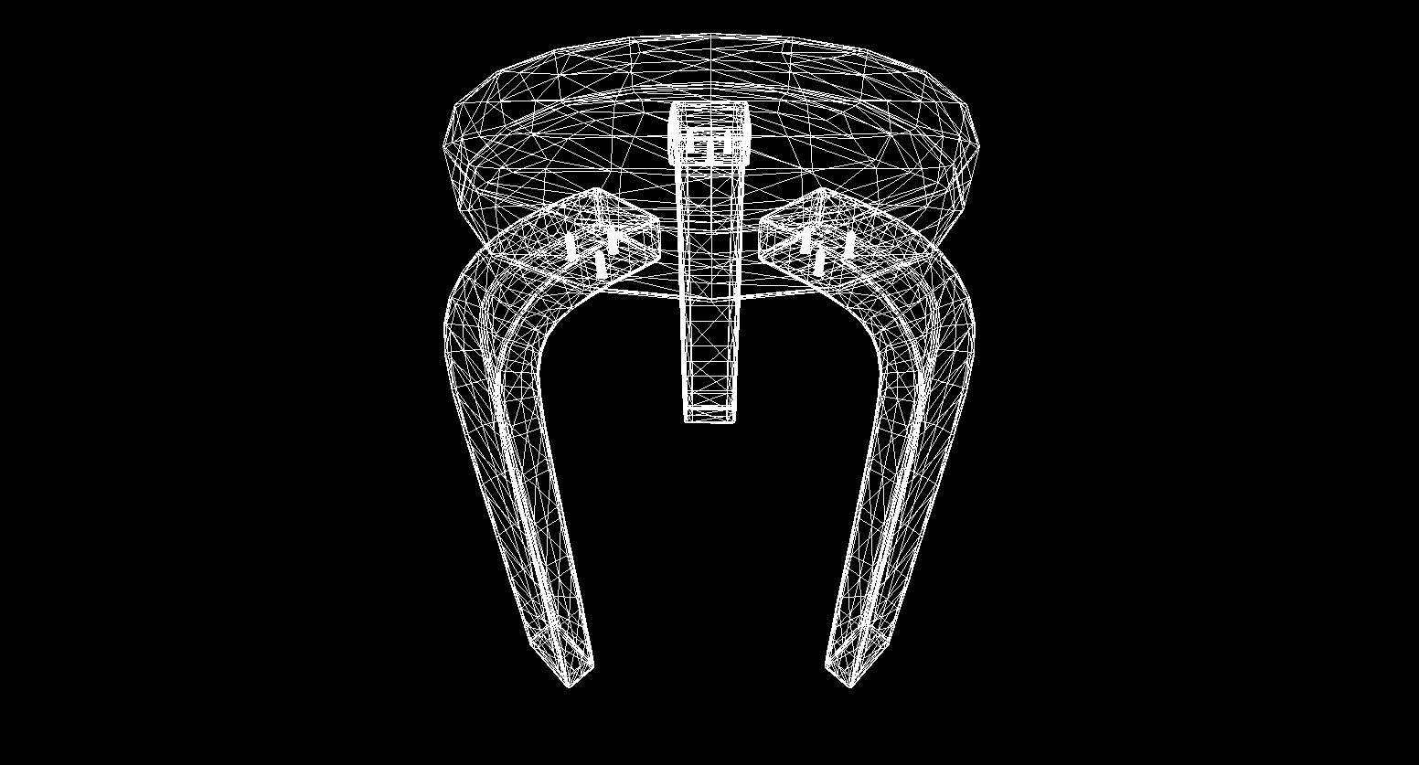
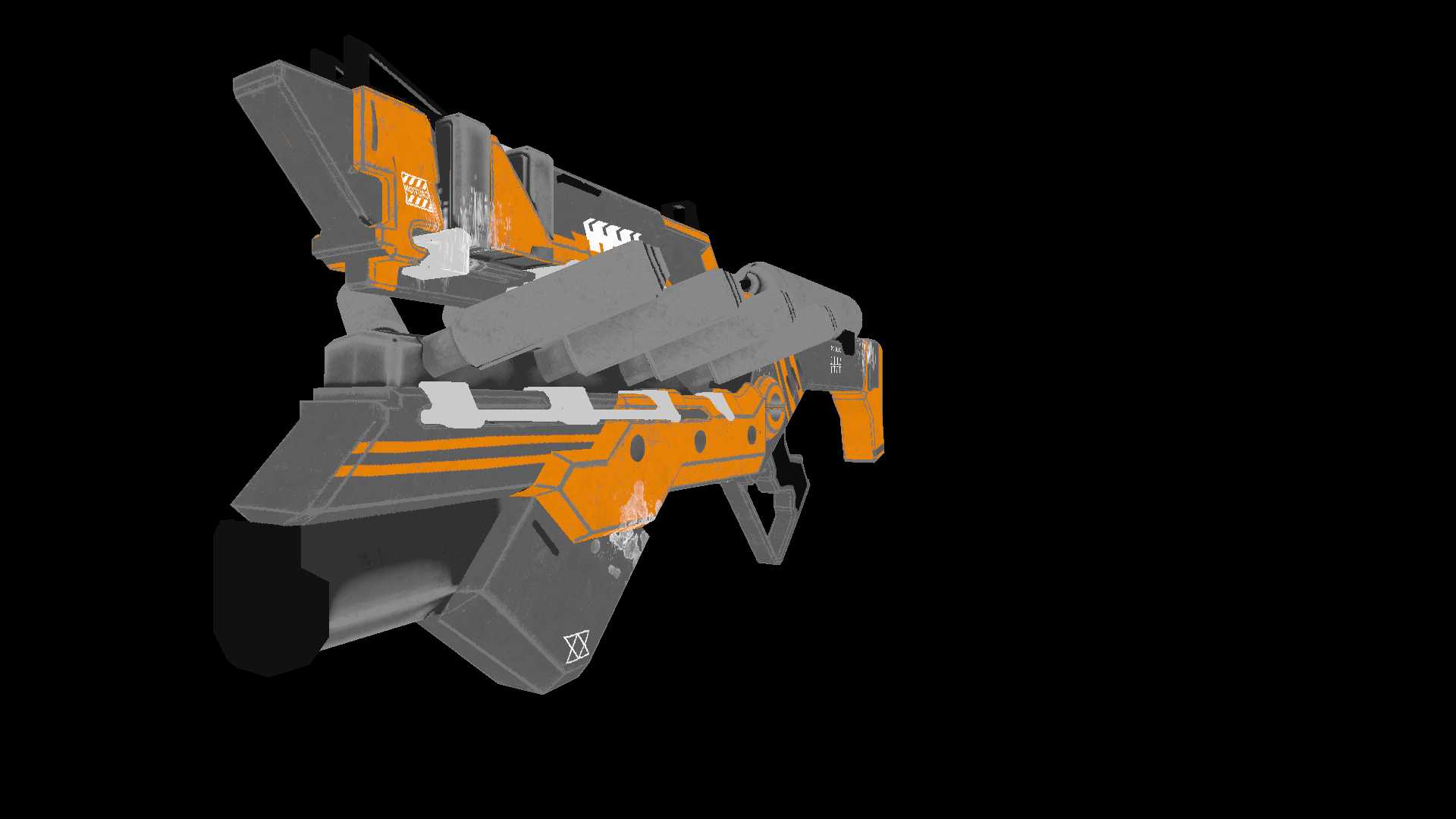
For a static scene, it will be enough to call the construction of the depth map once, then use it in all frames. As a test I am using a less polygonal model of the gun. This is the output image:
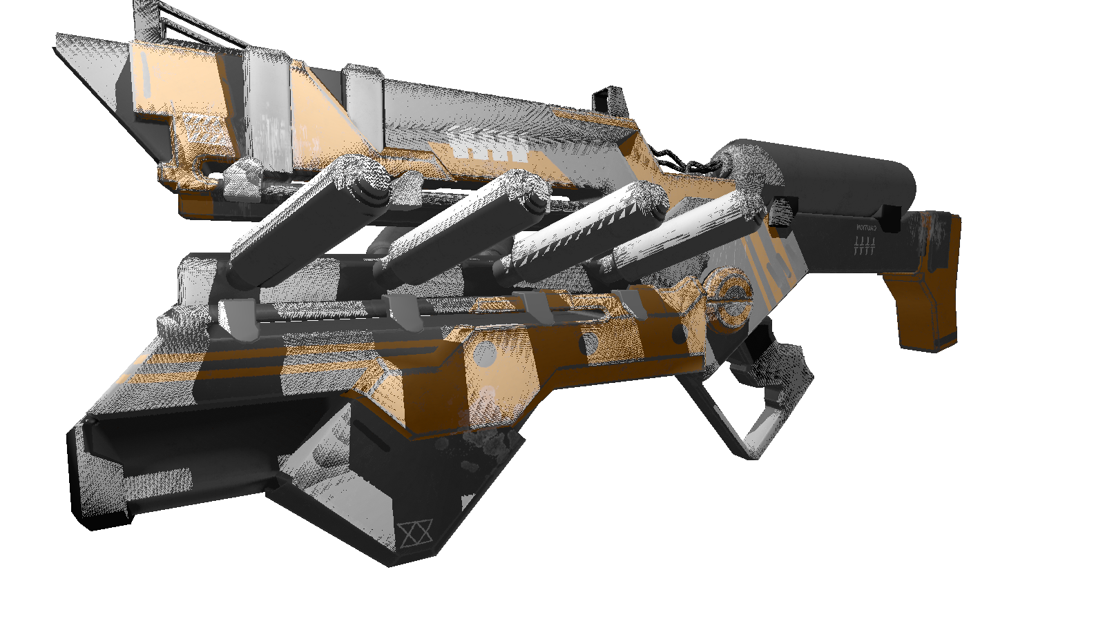
Many of you have probably noticed the artifacts of this shader (black dots unprocessed by light). Again, turning to the omniscient network, I found a description of this effect with the nasty name "shadow acne" (forgive me people with a complex appearance). The essence of such "gaps" is that we use the limited resolution of the depth map to define the shadow. This means that several vertices when rendering receive one value from the depth map. The most susceptible to such an artifact are surfaces on which light falls at a shallow angle. The effect can be corrected by increasing the render resolution of the lights, but there is a more elegant way . It consists in addinga specific shift for depth depending on the angle between the light beam and the surface . This can be done using the dot product.
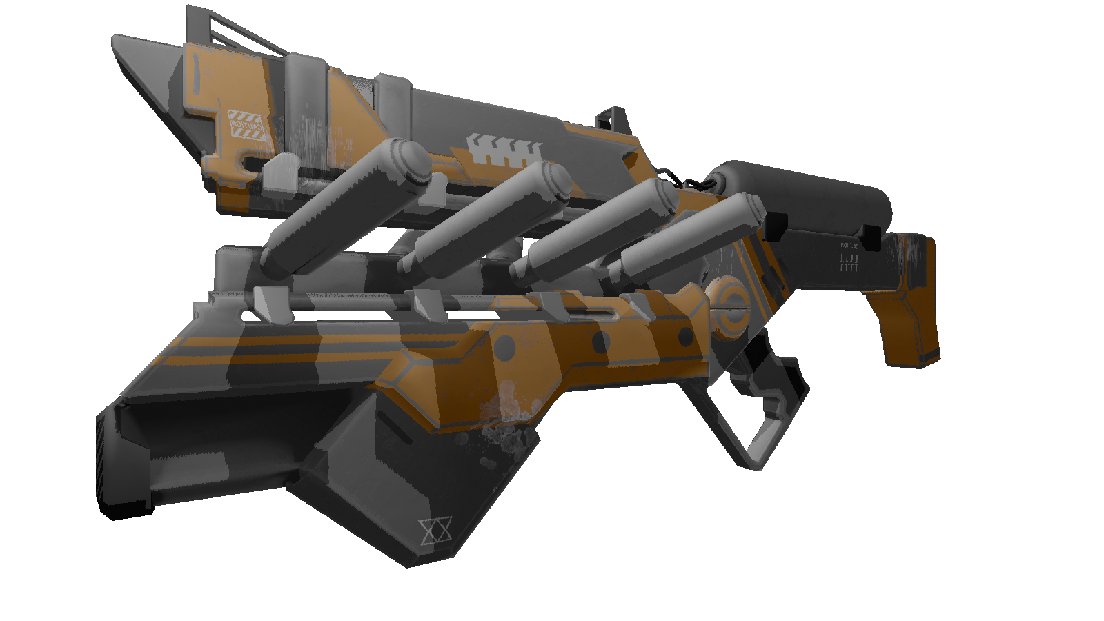
Improved shadows
public class ShadowMappingShader : IShader
{
    public Enviroment Enviroment { get; set; }
    public Rasterizer Rasterizer { get; set; }
    public Camera Camera => Rasterizer.Camera;
    public Pivot Pivot => Camera.Pivot;
    public Vertex[] ZBuffer => Rasterizer.ZBuffer;
    public float LightIntensivity { get; set; }

    public ShadowMappingShader(Enviroment enviroment, Rasterizer rasterizer, float lightIntensivity)
    {
        Enviroment = enviroment;
        LightIntensivity = lightIntensivity;
        Rasterizer = rasterizer;
        //     ,
        //  /
        Camera.OnRotate += () => UpdateDepthMap(Enviroment.Primitives);
        Camera.OnMove += () => UpdateDepthMap(Enviroment.Primitives);
        Enviroment.OnChange += () => UpdateDepthMap(Enviroment.Primitives);
        UpdateVisible(Enviroment.Primitives);
    }
    public void ComputeShader(Vertex vertex, Camera camera)
    {
        //
        var gPos = camera.Pivot.ToGlobalCoords(vertex.Position);
        //
        var lghDir = Pivot.Center - gPos;
        var distance = lghDir.Length();
        var local = Pivot.ToLocalCoords(gPos);
        var proectToLight = Camera.ScreenProection(local).ToPoint();
        if (proectToLight.X >= 0 && proectToLight.X < Camera.ScreenWidth && proectToLight.Y >= 0
            && proectToLight.Y < Camera.ScreenHeight)
        {
            int index = proectToLight.Y * Camera.ScreenWidth + proectToLight.X;
            var n = Vector3.Normalize(vertex.Normal);
            var ld = Vector3.Normalize(lghDir);
            //
            float bias = (float)Math.Max(10 * (1.0 - VectorMath.Cross(n, ld)), 0.05);
            if (ZBuffer[index] == null || ZBuffer[index].Position.Z + bias >= local.Z)
            {
                vertex.Color = Color.FromArgb(vertex.Color.A,
                    (int)Math.Min(255, vertex.Color.R + LightIntensivity / distance),
                    (int)Math.Min(255, vertex.Color.G + LightIntensivity / distance),
                    (int)Math.Min(255, vertex.Color.B + LightIntensivity / distance));
            }
        }
        else
        {
            vertex.Color = Color.FromArgb(vertex.Color.A,
                    (int)Math.Min(255, vertex.Color.R + (LightIntensivity / distance) / 15),
                    (int)Math.Min(255, vertex.Color.G + (LightIntensivity / distance) / 15),
                    (int)Math.Min(255, vertex.Color.B + (LightIntensivity / distance) / 15));
        }
    }
    public void UpdateDepthMap(IEnumerable<Primitive> primitives)
    {
        Rasterizer.ComputeVisibleVertices(primitives);
    }
}
Bonus
, , 3 . , .
:
:
FPS 1-2 /. realtime. , , .. cpu.
, , 3 . , .
:
            float angle = (float)Math.PI / 90;
            var shader = (preparer.Shaders[0] as PhongModelShader);
            for (int i = 0; i < 180; i+=2)
            {
                shader.Lights[0] = = new Light()
                    {
                        Pos = shader.Lights[0].Pos.Rotate(angle , Axis.X) ,
                        Intensivity = shader.Lights[0].Intensivity
                    };
                Draw();
            }
:
- : 220 .
- : 1920x1080.
- : Phong model shader
- : cpu — core i7 4790, 8 gb ram
FPS 1-2 /. realtime. , , .. cpu.
Conclusion
I consider myself a beginner in 3D graphics, I do not exclude the mistakes I made in the course of the presentation. The only thing I rely on is the practical result obtained in the process of creation. You can leave all the corrections and optimizations (if any) in the comments, I will be happy to read them. Link to the project repository .