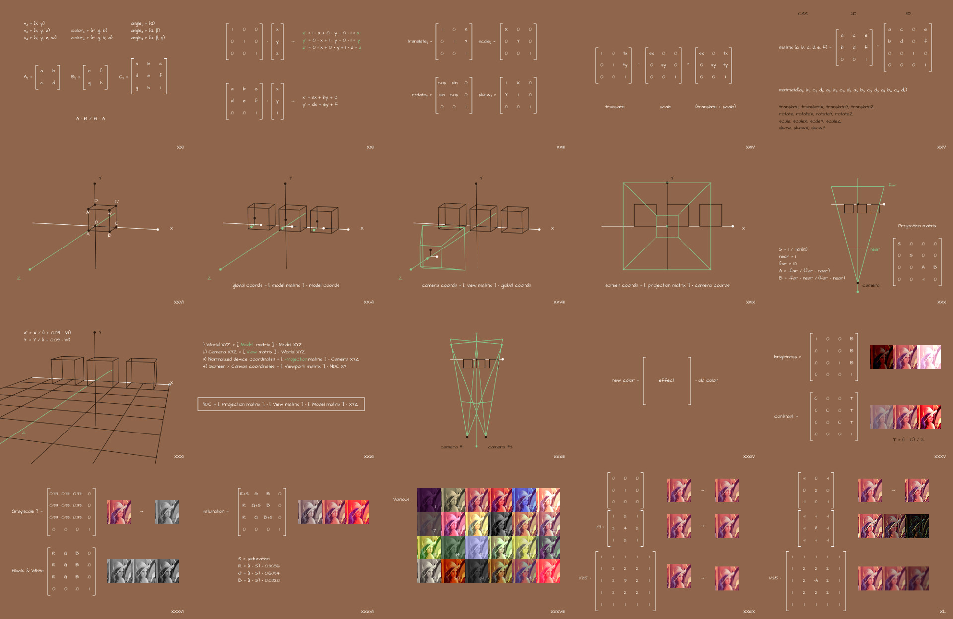
The last time we talked about the graphs and trajectories for the stop motion animation, and today it will be about the matrix. We will figure out how to build basic transformations in CSS, SVG and WebGL, build the display of the 3D world on the screen with our own hands, along the way drawing a parallel with a tool such as Three.js, and also experiment with filters for photos and figure out what for such magic lies at their core.
Let me remind you that in this series of articles we get acquainted with various things from the field of mathematics that scare layout designers, but can be useful in solving work problems. We try to avoid unnecessary theorization, preferring pictures and explanation on the fingers, with an emphasis on practical applications in the frontend. In this regard, the formulations in some places may not be entirely accurate from the point of view of mathematics, or not quite complete. The purpose of this article is to give a general idea of what happens and where to start if something happens.
Scripts for generating images in the style of this article series are on GitHub , so if you want to figure out the same, you know what to do.
Few definitions
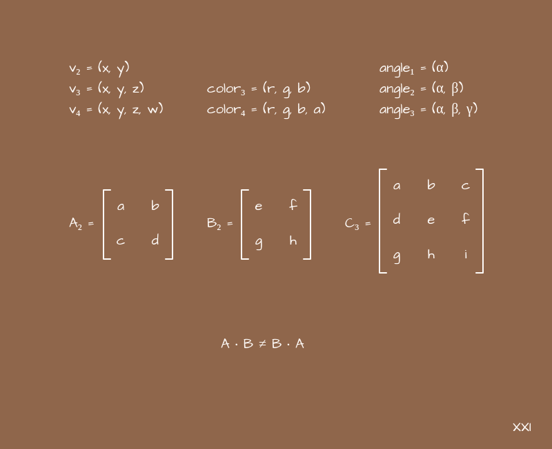
A matrix in mathematics is such an abstraction, we can say that it is a data type in a sense, and writing it in the form of a rectangular table. The number of columns and rows can be anything, but on the web we are almost always dealing with square matrices 2x2, 3x3, 4x4, and 5x5.
We also need a definition such as a vector. I think from school geometry you can recall the definition associated with the words "length" and "direction", but in general in mathematics a lot of things can be called a vector. In particular, we will talk about a vector as an ordered set of values. For example, coordinates of the form (x, y) or (x, y, z), or a color in the format (r, g, b) or (h, s, l, a), etc. Depending on how many elements are included in such a set, we will talk about a vector of one dimension or another: if two elements are two-dimensional, three are three-dimensional, etc. Also, within the framework of the topics under consideration, it can sometimes be convenient to think of a vector as a matrix of sizes 1x2, 1x3, 1x4, etc. Technically, we could limit ourselves to just the term "matrix", but we will still use the word "vector" to separate these two concepts from each other,at least in a logical sense.
For matrices, as well as for vectors, various operations are defined that can be done with them. In particular, multiplication. We constantly multiply them among ourselves. The multiplication algorithm itself is not very complicated, although it may seem a little confusing:
function multiplyMatrices(a, b) {
    const m = new Array(a.length);

    for (let row = 0; row < a.length; row++) {
        m[row] = new Array(b[0].length);

        for (let column = 0; column < b[0].length; column++) {
            m[row][column] = 0;

            for (let i = 0; i < a[0].length; i++) {
                m[row][column] += a[row][i] * b[i][column];
            }
        }
    }

    return m;
}
But for us, in fact, it is not so important to constantly remember the principle of its operation when solving everyday problems. Here we mention it rather for completeness, to provide context for further examples.
When dealing with complex entities in mathematics, it is very useful to abstract. As here - we will often talk about multiplication, but we will not pay attention to what kind of arithmetic operations in what order occur there. We know the multiplication is defined - and that's enough for the job.
We will only use square matrices in a very specific set of problems, so a set of simple rules will suffice:
- You can only multiply matrices of the same dimension.
- We multiply the matrix by the matrix - we get the matrix.
- You can multiply a matrix by a vector - we get a vector.
- The order of multiplication is important.
We will mainly use left-to-right multiplication, as it is more familiar and suitable for explanations, but in some books or libraries you may find it right to left, and all matrices will be mirrored diagonally. This does not in any way affect the essence of the manipulations taking place, so we will not dwell on this, but if you copy-paste something, pay attention.
Also for further work we will need such a concept as the identity matrix. This is a matrix with ones on the main diagonal and zeros in all other cells. The multiplication algorithm is built in such a way that multiplying the identity matrix by another matrix - we get the same matrix. Or a vector, if we are talking about a vector. In other words, the identity matrix plays the role of one in the usual multiplication of numbers. This is a neutral thing that "does not affect anything" when multiplied.
And the last thing we need is the example shown in the picture above. It is like a special case of multiplying a matrix by a vector, when the last row of the matrix is "a piece of the identity matrix", and the last element of the vector is also equal to 1.
In this example, we are using the letters (x, y), and as you might have guessed, the next discussion will focus on coordinates in 2D. But why add a third coordinate and leave it as one? - you ask. It's all about convenience, or even better, versatility. We very often add +1 coordinate to simplify calculations, and work with 2D goes with 3x3 matrices, work with 3D - with 4x4 matrices, and work with 4D, for example, with colors in the format (r, g, b, a) goes with matrices 5x5. At first glance, this seems like a crazy idea, but later we will see how it unifies all operations. If you want to understand this topic in more detail, you can google the expression "uniform coordinates".
But enough theory, let's move on to practice.
I. Basic transformations in computer graphics
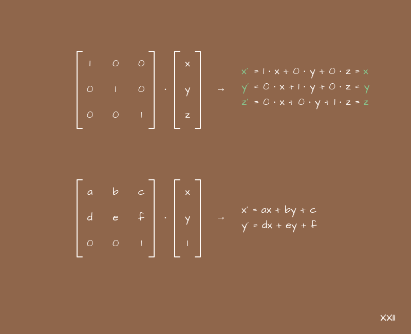
Let's take the expressions from the above example and see them as they are, outside the context of matrices:
newX = a*x + b*y + c
newY = d*x + e*y + f
You can think of this as the parametric equations that we plotted last time. What happens if you set these or those coefficients in them? Let's start with the next option:
newX = 1*x + 0*y + 0 = x
newY = 0*x + 1*y + 0 = y
Nothing changes here - the new coordinates (x, y) are identical to the old ones. If we substitute these coefficients into the matrix and look closely, we will see that we get the identity matrix.
What happens if you take other coefficients? For example, these are:
newX = 1*x + 0*y + A = x + A
newY = 0*x + 1*y + 0 = y
We will get an offset along the X axis. But what else could have happened here? If this is not obvious to you, then it is better to return to the first part, where we talked about charts and coefficients.
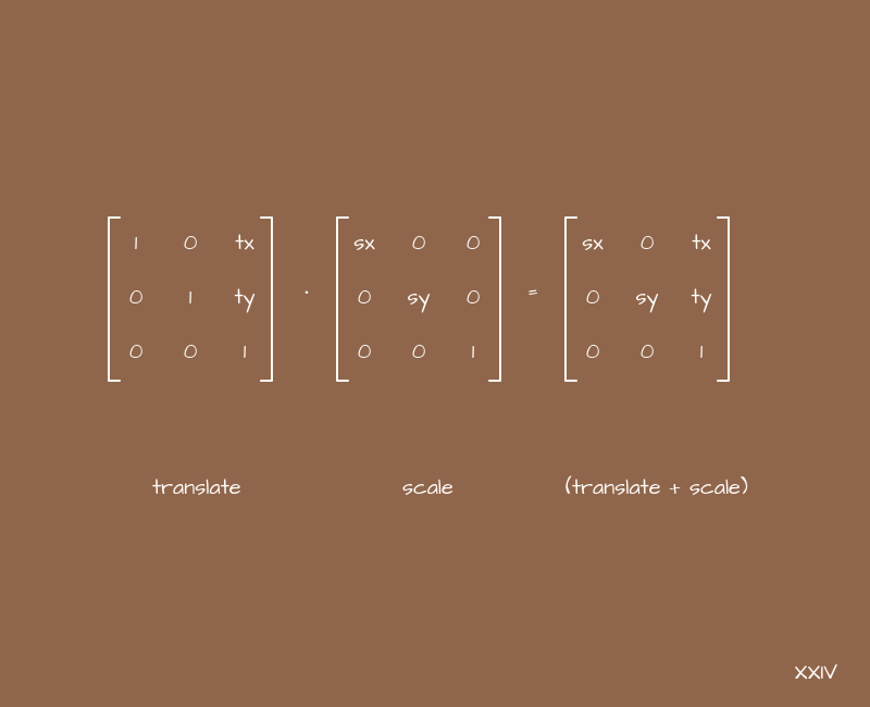
Changing these 6 coefficients - a, b, c, d, e, f - and observing the changes in x and y, sooner or later we will come to four of their combinations, which seem useful and convenient for practical use. Let's write them right away in the form of matrices, returning to the original example:

The names of these matrices speak for themselves. When multiplying these matrices by vectors with the coordinates of some points, objects on the scene, etc. we get new coordinates for them. Moreover, we operate with intuitive transformations - movement, scaling, rotation and tilt, and the coefficients determine the severity of a particular transformation along the corresponding axes.
It is often convenient to think of matrices as transformations for something, such as coordinates. This is another word about abstractions.
Transforms can be stacked. In terms of matrices, we will use the multiplication operation, which can be a little confusing, but this is a spoken language overhead. If we need to shift some object to the side and increase, then we can take a matrix for displacement, a matrix for scaling, and multiply them. The result will be a matrix that gives both offset and scaling at the same time. It only remains to transform each point of our object with its help.
Basic transformations in CSS
But these are all words. Let's see what it looks like in a real front-end. In CSS, we (all of a sudden) have a matrix function. It looks something like this in the context of the code:
.example {
    transform: matrix(1, 0, 0, 1, 0, 0);
}
Many newbies who see it for the first time are covered by the question - why are there six parameters? This is strange. It would have been 4 or 16 - it still didn't go where, but 6? What are they doing?
But in reality everything is simple. These six parameters are the very coefficients from which we have just assembled the matrices for the basic transformations. But for some reason they were arranged in a different order:

Also in CSS there is a function matrix3d in order to set a 3D transformation using a matrix. There are already 16 parameters, exactly to make a 4x4 matrix (do not forget that we add +1 dimension).
Matrices for basic 3D transformations are built in the same way as for 2D, only more coefficients are needed to arrange them not in two coordinates, but in three. But the principles are the same.
Naturally, every time it would be strange to fence the matrix and monitor the correct placement of the coefficients when working with simple transformations in CSS. We programmers usually try to make our life easier. So we now have short functions in CSS for creating individual transformations - translateX, translateY, scaleX, etc. Usually we use them, but it is important to understand that inside they create the same matrices that we talked about, simply hiding this process from us behind another layer of abstraction.
The same translate, rotate, scale, and skew transformations, as well as the universal matrix function for defining transformations, are present in SVG. The syntax is slightly different, but the essence is the same. When working with 3D graphics, for example with WebGL, we will also resort to the same transformations. But more on that later, now it is important to understand that they are everywhere, and they work everywhere according to the same principle.
Subtotals
Let's summarize the above:
- Matrices can be used as transformations for vectors, in particular for the coordinates of some objects on the page.
- We almost always operate with square matrices and add +1 dimension to simplify and unify calculations.
- There are 4 basic transformations - translate, rotate, scale and skew. They are used everywhere from CSS to WebGL and work in a similar way everywhere.
II. DIY 3D scene construction
A logical development of the topic about coordinate transformation will be the construction of a 3D scene and displaying it on the screen. In one form or another, this task is usually present in all computer graphics courses, but in front-end courses it is usually not. We will see, maybe a little simplified, but nevertheless a full-fledged version of how you can make a camera with different viewing angles, what operations are needed to calculate the coordinates of all objects on the screen and build a picture, and also draw parallels with Three.js - the most popular tool for working with WebGL.
A reasonable question should arise here - why? Why learn to do everything with your hands if you have a ready-made tool? The answer lies in performance issues. You've probably visited sites with contests like Awwwards, CSS Design Awards, FWA and the like. Remember how performing sites are participating in these contests? Yes, almost everyone there slows down, lags when loading and makes the laptop hum like an airplane! Yes, of course, the main reason is usually complex shaders or too much DOM manipulation, but the second is the incredible amount of scripts. This has a disastrous effect on the loading of such sites. Usually everything happens like this: you need to do something on WebGL - take some kind of 3D engine (+ 500KB) and some plugins for it (+ 500KB);you need to make an object fall or something flying apart - they take a physics engine (+ 1MB, or even more); you need to update some data on the page - well, add some SPA-framework with a dozen plugins (+ 500KB), etc. And in this way, several megabytes of scripts are typed, which not only need to be downloaded by the client (and this is in addition to the large pictures), but also the browser will do something with them after downloading - they do not just fly to it. Moreover, in 99% of cases, until the scripts work, the user will not see all the beauty that he would need to show from the very beginning.what the client needs to download (and this is in addition to the large pictures), so the browser will do something with them after loading - they don't just come to him for a reason. Moreover, in 99% of cases, until the scripts work, the user will not see all the beauty that he would need to show from the very beginning.what the client needs to download (and this is in addition to the large pictures), so the browser will do something with them after loading - they don't just come to him for a reason. Moreover, in 99% of cases, until the scripts work, the user will not see all the beauty that he would need to show from the very beginning.
A popular belief says that every 666KB of scripts in production increases page load time by enough time for a user to send a site developer to the next circle of hell. Three.js in the minimum configuration weighs 628KB ...
Moreover, often tasks simply do not require the connection of complex tools. For example, to show a couple of planes with textures in WebGL and add a couple of shaders to make the pictures diverge in waves, you don't need all of Three.js. And to make an object fall, you don't need a full-fledged physics engine. Yes, it will likely speed up your work, especially if you are familiar with it, but you will pay for it with the users' time. Here everyone decides for himself what is more profitable for him.
Coordinate transformation chain
In fact, the essence of coordinate transformations for constructing a 3D scene on your screen is quite simple, but we will still analyze it step by step, since most likely, this process will be something new for many layout designers.
So that's it. Let's say a designer has drawn a 3D model. Let it be a cube (in the examples we will use the simplest constructions so as not to complicate the illustration out of the blue):

What is this model like? In fact, it is a set of points in some coordinate system and a set of relationships between them so that you can determine between which points the planes should be located. The question of planes in the context of WebGL will rest on the shoulders of the browser itself, and coordinates are important for us. You need to figure out exactly how to transform them.
The model, as we said, has a coordinate system. But usually we want to have a lot of models, we want to make a scene with them. The scene, our 3D world, will have its own global coordinate system. If we just interpret the coordinates of the model as global coordinates, then our model will be located as if "in the center of the world." In other words, nothing will change. But we want to add many models to different places in our world, something like this:
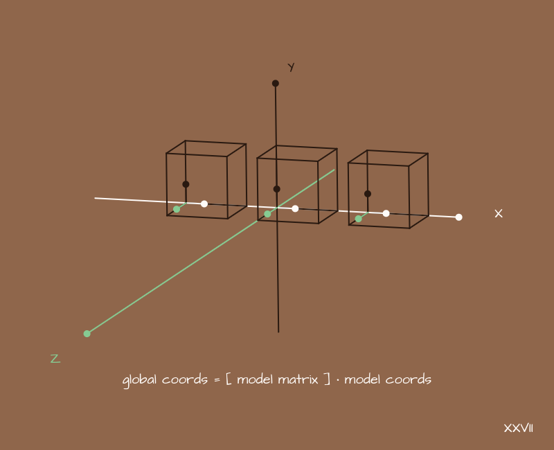
What to do? You need to convert the coordinates of each individual model to global coordinates. The position of the model in space is set by offsets, rotations and scaling - we've already seen these basic transformations. Now we need to build a transformation matrix for each model, which will store in itself just this information about where the model is in relation to the world, and how it is rotated.
For example, for cubes there will be approximately the following matrices:
//     .
//   «  »      .
const modelMatrix1 = [
    [1, 0, 0, 0],
    [0, 1, 0, 0],
    [0, 0, 1, 0],
    [0, 0, 0, 1]
];

// ,     X.
const modelMatrix2 = [
    [1, 0, 0, 1.5],
    [0, 1, 0, 0  ],
    [0, 0, 1, 0  ],
    [0, 0, 0, 1  ]
];

// ,     X   .
const modelMatrix3 = [
    [1, 0, 0, -1.5],
    [0, 1, 0, 0   ],
    [0, 0, 1, 0   ],
    [0, 0, 0, 1   ]
];
Further, we will act approximately as follows:
    {
       = [    ] *
}
Accordingly, each model needs its own matrix.
Similarly, you can make a chain of some objects. If a bird has to flap its wings, then it will be appropriate to translate the coordinates of the wing points into the coordinates of the bird, and then into the global world coordinates. It will be much easier to guess the wing trajectory directly in global coordinates. But this is so, by the way.
Next, you need to decide on which side we will look at the world. I need a camera.

A camera is such an abstraction, like an imitation of a physical camera. It has coordinates and some tilt angles that set its location in global coordinates. Our task is to transform a set of now global coordinates into a camera coordinate system. The principle is the same as in the previous example:
     {
        = [   ] *
}
, , . !
Let's look at the scene from the place where our conditional camera is:
Now, having converted all points to the camera coordinate system, we can simply discard the Z axis, and interpret the X and Y axes as "horizontal" and "vertical". If you draw all the points of the models on the screen, you get a picture, as in the example - no perspective and it is difficult to understand which part of the scene actually falls into the frame. The camera is like an infinite size in all directions. We can somehow adjust everything so that what we need fits on the screen, but it would be nice to have a universal way of determining which part of the scene will fall into the camera's field of view and which will not.
With physical cameras, we can talk about such a thing as a viewing angle. Why not add it here too?
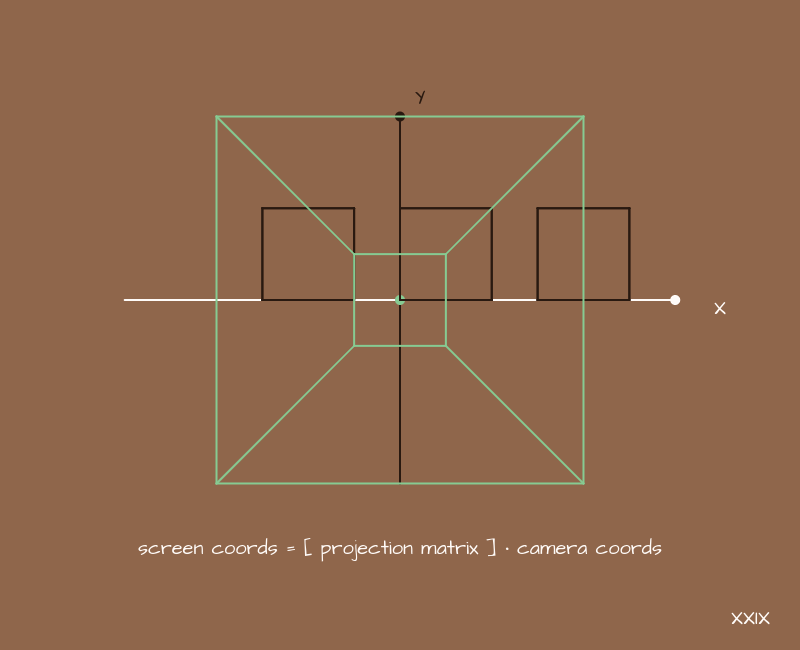
For this we need another matrix - the projection matrix. In general, it can be built in different ways. Depending on what is taken as the initial parameters, you get a slightly different type of this very matrix, but the essence will be the same. We'll take the following slightly simplified version:
//     90
const s = 1 / (Math.tan(90 * Math.PI / 360));
const n = 0.001;
const f = 10;

const projectionMatrix  = [
    [s, 0, 0,          0],
    [0, s, 0,          0],
    [0, 0, -(f)/(f-n), -f*n/(f-n)],
    [0, 0, -1,         0]
];
The projection matrix, one way or another, contains three parameters - this is the viewing angle, as well as the minimum and maximum distance to the points with which you work. It can be expressed in different ways, used in different ways, but these parameters will be in this matrix in any case.
I understand that it is never obvious why the matrix looks exactly like this, but to derive it with explanations, you need formulas for 2-3 pages. This once again brings us back to the idea that it is useful to abstract - we can operate with a more general result, without going into small details where it is not necessary to solve a specific problem.
Now, making the already familiar transformations:
       {
      = [   ] *
}
We will get in our field of vision exactly what we expect. Increasing the angle - we see most of all on the sides, decreasing the angle - we see only what is closer to the direction where the camera is directed. PROFIT!

But actually no. We forgot about the perspective. A hopeless picture is needed in few places, so you need to add it somehow. And here, all of a sudden, we don't need matrices. The task looks very difficult, but it is solved by the banal division of the X and Y coordinates by W for each point:
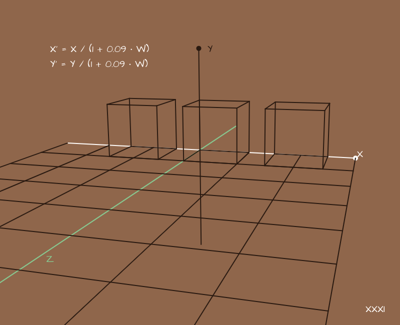
* Here we have shifted the camera to the side and added parallel lines "on the floor" to make it clearer where this very perspective appears.
Choosing the coefficients to our taste, we will get different perspective options In a sense, the coefficients here determine the type of lens, how much it “flattens” the surrounding space.
Now we have a complete picture. You can take the X and Y coordinates for each point and draw it on the screen in any way you like.
In general, this is enough to build a scene, but in real projects you may also encounter an additional transformation related to scaling at the very end. The idea is that after the projection we get the coordinates (x, y) within 1, normalized coordinates, and then we multiply them by the size of the screen or canvas, getting the coordinates for display on the screen. This extra step takes the canvas size out of all calculations, leaving it only at the very end. This is sometimes convenient.
Here you probably got a headache from the amount of information, so let's slow down and repeat all the transformations in one place:
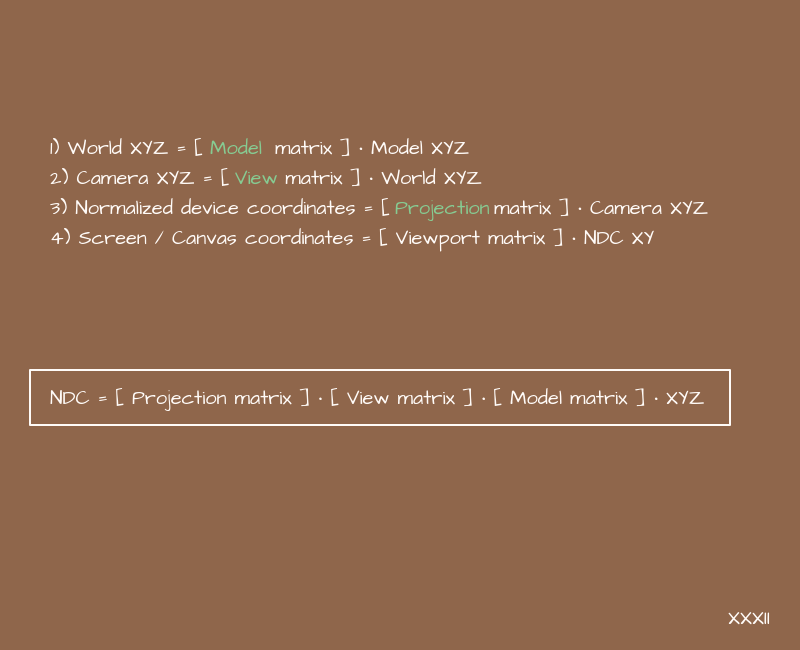
If you combine these transformations into one, you get a little engine.
How does it look like in Three.js?
Now that we understand where this little engine came from, let's look at an example of the default vertex shader in Three.js that “does nothing”:
void main() {
    gl_Position = projectionMatrix * modelViewMatrix * vec4(position, 1.0);
}
or more fully:
void main() {
    gl_Position = projectionMatrix * viewMatrix * modelMatrix * vec4(position, 1.0);
}
Does he remind you of anything? Yes, this is this particular engine. And by "does nothing" we mean that it just does all the work of recalculating coordinates, based on matrices carefully passed from Three.js. But no one bothers to make these matrices with their own hands, right?
Camera types in computer graphics and Three.js
The topic of camera types is not directly related to matrices, but still we will devote a couple of minutes to it, since we are still talking about Three.js, and sometimes people have a mess in their heads about this.
The camera is an abstraction. It helps us think in the 3D world in the same way as we think in the real world. As we said, a camera has a position in space, a direction in which it is looking, and an angle of view. All this is specified using two matrices and, possibly, additional division of coordinates to create perspective.
In computer graphics, we have two types of cameras - "with perspective" and "without perspective". These are two fundamentally different types of cameras in technical terms, requiring different steps to obtain an image. And that's all. There is nothing else. Everything else is their combinations, some more complex abstractions. For example, Three.js has a stereo camera - this is not some kind of "special type" camera in technical terms, but just an abstraction - two cameras slightly spaced apart in space and located at an angle:

For each half of the screen, we take our own camera and it turns out stereo picture. And CubeCamera is 6 ordinary cameras located on different sides from a point, nothing more.
What's next?
The next step, after obtaining the coordinates of the objects, is to determine which objects will be visible and which will be hidden behind others. In the context of WebGL, the browser will do this itself. Well, there will still be related tasks such as applying textures to them, calculating lighting by normals, shadows, post-processing images, etc. But we have already done the most important and difficult part to understand. It's great. In fact, many generative things do not need these very textures and lighting, so it may very well be that the knowledge gained now will be enough to work with them.
By the way, casting a shadow from an object onto a plane is nothing more than a projection of this object onto this very plane at a certain angle, followed by mixing colors. The process is inherently very similar to the camera, but it also adds an angle between the plane of the projection and the "direction of view".
About textures and effects for images on WebGL, including without libraries, we talked about in previous articles more than once. You can refer to them if you are interested in this topic. Thus, by combining all this knowledge together, we can build full-fledged colorful 3D things with our own hands.
3D- . – - . , Three.js . , , , - , - . , .
Now is the time to summarize the above so that there is room in your head for the next use case for matrices.
So:
- You can build a 3D world and calculate the coordinates of objects on the screen with your own hands using a train from matrices.
- In the 3D world, we operate with such an abstraction as a “camera”. It has a location, direction and viewing angle. All this is set using the same matrices. And there are two basic camera views - perspective and non-perspective.
- In the context of WebGL, hand-drawing an image on the screen or physical calculations can often remove heavy dependencies and speed up page loading. But it is important to strike a balance between your scripts, ready-made tools, and alternative options for solving problems, paying attention not only to your convenience, but also to issues of download speed and ultimate performance, including on phones.
III. Filters for images
Finally, we will look at such an area of application of matrices as filters for images. If we consider a color in RGBA format as a vector, then we can assume that here we can apply a transformation similar to the one we used with coordinates:
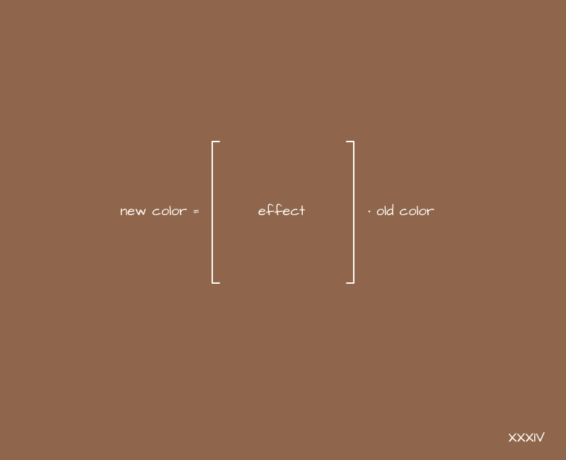
And apply this to the picture according to the obvious principle:
    {
       = [  ] *
}
If the identity matrix acts as a matrix, nothing will change, we already know that. What happens if you apply filters similar to translate and scale transformations?

OU. The result is brightness and contrast filters. Interesting.
When experimenting with such filters, you should always remember to adjust the values so that the image is not overexposed. If you are multiplying something by a large number, you most likely need to subtract or divide something somewhere. As shown in the previous example.
How to make a black and white image from a color one? The first thing that comes to mind is to add the RGB channel values, divide by 3, and use the resulting value for all three channels. In matrix format, it will look something like this:

And although we did get a black and white image, it can still be improved. Our eye actually perceives the lightness of different colors in different ways. And in order to somehow convey this during desaturation, we make different coefficients for each RGB channel in this matrix.
The example below will present the generally accepted values for these coefficients, but no one bothers to play with them. In total, these coefficients should give 1, but depending on their proportions, we will get slightly different black and white images. This can, to some extent, simulate different color reproduction when working with film cameras.
And if we also multiply the main diagonal a little, then we get a universal saturation filter:

It works in both directions - both in desaturation (you can reach a completely black and white image), and in saturation. It all depends on the corresponding coefficient.
In general, you can play with filters for a long time, getting a variety of results:
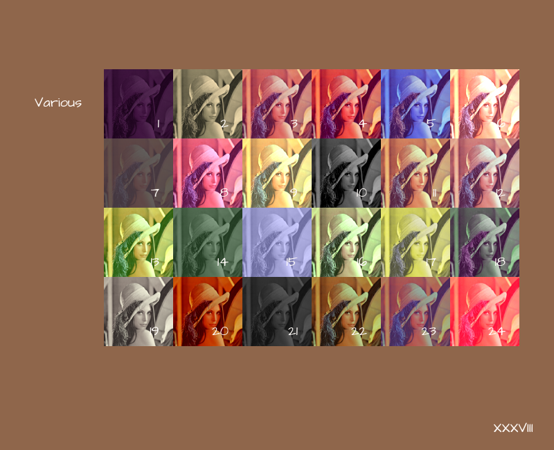
* The matrices used in this example can be viewed on GitHubif you suddenly need them. To be inserted into the article, their volume will be excessive.
But let's still pay a little attention to where this actually applies. It is clear that the very idea of replacing the color for each pixel suggests shaders for processing a photo, or for post-processing some 3D scene, but maybe it's still somewhere in the frontend?
Filters in CSS
In CSS, we have a filter property. And there, in particular, there are such options for filters related to colors:
- brightness (we made it)
- contrast (done)
- invert (same as contrast, only main diagonal coefficients with a different sign)
- saturate (done)
- grayscale (as already noted, this is a special case of saturate)
- sepia (a very vague concept, different versions of sepia are obtained by playing with coefficients, where we somehow reduce the presence of blue)
And these filters accept coefficients as input, which are then substituted in one form or another into the matrices that we made earlier. Now we know how this magic works from the inside. And now it is clear how these filters are combined in the bowels of the CSS interpreter, because everything here is built according to the same principle as with coordinates: multiply matrices - add effects. True, there is no custom function matrix in this property in CSS. But it is in SVG!
Filter matrices in SVG
Within SVG, we have feColorMatrix, which is used to create filters for images. And here we already have complete freedom - we can make a matrix to our taste. The syntax is something like this:
<filter id=’my-color-filter’>
    <feColorMatrix in=’SourceGraphics’
        type=’matrix’,
        values=’1 0 0 0 0
                0 1 0 0 0
                0 0 1 0 0
                0 0 0 1 0
                0 0 0 0 1‘
    />
</filter>
You can also apply SVG filters to regular DOM elements within CSS, there is a special url function for this ... But I didn't tell you that!
In fact, SVG filters within CSS are still not supported by all browsers (not pointing the finger at IE), but there are rumors that Edge is finally moving to the chromium engine, and older versions will lose support in the foreseeable future, so it's time for this technology master, you can do a lot of interesting things with it.
What else happens?
In addition to the effects for pictures, built on the principle of transformations, there are various things built on pixel displacements, mixing their colors and other manipulations, where the matrix can be a good format for storing data by which this very manipulation should take place.
Kernel matrix
In particular, in the frontend, we come across such a thing as the kernel matrix, and its associated effects. The point is simple - there is a square matrix, usually 3x3 or 5x5, although there may be more, and coefficients are stored in it. In the center of the matrix - for the "current" pixel, around the center - for neighboring pixels. If the matrix is 5x5, then another layer appears around the center - for pixels located one from the current one. If 7x7 - then another layer, etc. In other words, we consider the matrix as such a two-dimensional field, on which you can arrange the coefficients at your discretion, already without reference to any equations. And they will be interpreted as follows:
    {
       =
           ,
}
A blank canvas is not very suitable for such tasks, but shaders are very even. But it is easy to guess that the larger the matrix, the more neighboring pixels we will use. If the matrix is 3x3, we will add 9 colors, if 5x5 - 25, if 7x7 - 49, etc. More operations - more load on the processor or video card. This will inevitably affect the performance of the page as a whole.
Whenever possible, use small matrices for similar effects if you need to overlay them somewhere in real time.
Within SVG, we have a special feConvolveMatrix tag, which is made just for creating such effects:
<filter id=’my-image-filter’>
    <feConvolveMatrix
        kernelMatrix=’0 0 0
                      0 1 0
                      0 0 0’
    />
</filter>
Here we have made a simple filter for the picture that does nothing - the new color for each pixel will be equal to the current one multiplied by 1, and the values for the colors of neighboring pixels will be multiplied by 0.
Note that different browsers render SVGs differently, and color rendering can also float very widely. Sometimes the difference is just catastrophic. So always test your SVG filters or use canvas, which is more predictable in our context.
If we start arranging the numbers in layers, from the larger to the smaller, we get blur:
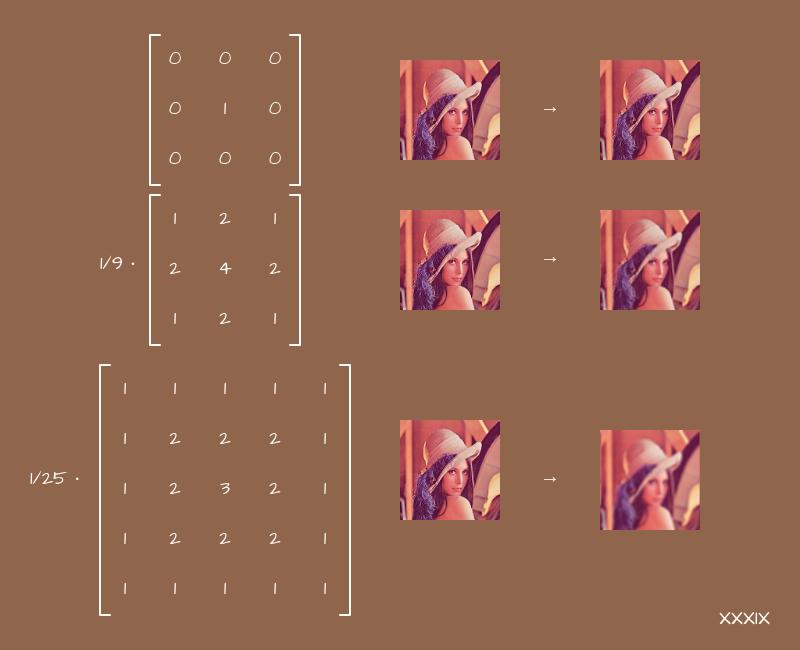
The larger the matrix, the more neighboring pixels we touch, the more the picture is washed. The main thing here is not to forget to normalize the values, otherwise the image will just light up.
Now, knowing how blur works, we can understand why its active use on a page within CSS or SVG leads to brakes - for each pixel the browser does a bunch of calculations.
If you start experimenting with changing the signs of the coefficients and arrange them in different patterns, you will get sharpen effects, edge detection and some others. Try to play with them yourself. This might be helpful.
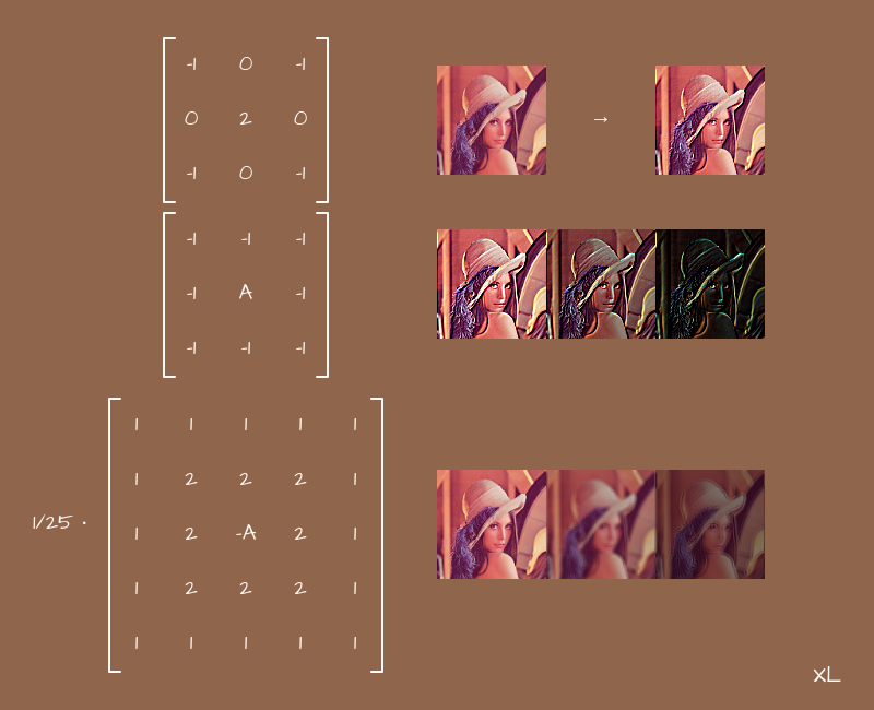
Thus, you can make different effects for photos, or even video, in real time, and make them dependent on some user action. It all depends on your imagination.
Subtotals
Let's summarize what was said in this part:
- Matrices can be used not only for transformations related to coordinates, but also for creating color filters. Everything is done according to the same principle.
- Matrices can be used as a convenient 2D storage for some data, including different coefficients for visual effects.
Conclusion
If we abstract a little from the intricate algorithms, then matrices will become an affordable tool for solving practical problems. With their help, you can calculate geometric transformations with your own hands, including within the framework of CSS and SVG, build 3D scenes, and also make all kinds of filters for photos or for post-processing images within the framework of WebGL. All these topics usually go beyond the classic frontend and are more related to computer graphics in general, but even if you do not solve these problems directly, knowing the principles of their solution will allow you to better understand how some of your tools work. It will never be superfluous.
I hope that this article helped you understand the topic of the practical application of matrices in the frontend, or at least gave you a foundation from which you can build on in your further development. If you think that some other topics related to mathematics or physics are worthy of the same review in the context of layout, then write your thoughts in the comments, perhaps one of the next articles will discuss them.