System start
The computer is completely turned off when it is disconnected from power and the capacitors on the motherboard are discharged. Before the era of smartphones, mobile phones often glitched and if a restart did not cure the problem, then you had to take out the battery and wait 10 seconds, because the OS software state was reset, while the chips on the motherboard and device controllers remained active, keeping the state, OS drivers for them just reconnected. 10 seconds - the time for the capacitors to discharge, the state of the chips is reset only after a complete shutdown.
If the PC is connected to an outlet or a battery, then it is in Stand-By mode, which means that a small voltage (5V) is supplied via the power bus from which some chips on the motherboard are powered. At least this is a system controlleris essentially a mini-computer that runs a large computer. Having received a notification about pressing the Power button, he asks the power supply / battery to supply more voltage and then initializes the entire chip-set, including the processor. Initialization includes transferring the motherboard firmware code and data ( BIOS / UEFI ) into RAM and setting the CPU to execute it.
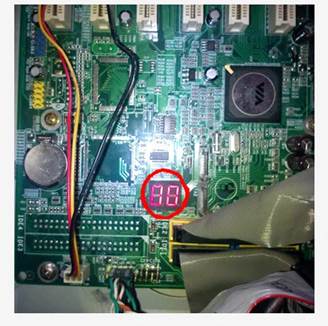
Thinking that the Power button is a switch that supplies electricity to the CPU and that starts executing the BIOS firmware from a previously known address is incorrect. Perhaps the old computers worked like that. The power button is located on its board, along with the status LEDs and is connected to the motherboard through a special connector. The picture below shows the contacts for the Power button, Reset, as well as LEDs with the Power status and hard disk reading. Pressing the power button is translated into a signal to the motherboard contacts, from where it reaches the system controller.
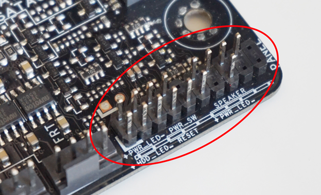
Pins on the motherboard for connecting the power button, power status LEDs, hard drive and speakers.
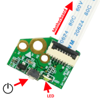
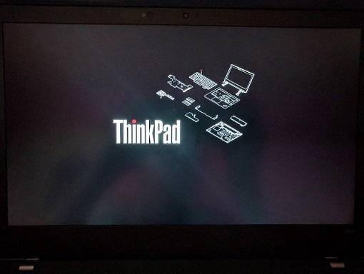
Laptop board with power button and status LED The system
controller has tremendous powers - to turn the computer on and off, execute code in kernel mode. Besides it, there may be other chips with comparable capabilities, such as Intel Management Engine or AMD Secure Technology (part of the CPU), which also work when the computer is "turned off". The Intel ME chip has an x86 CPU running MINIX 3 operating system . What he can do:
- Turn the computer on and off, i.e. execute programs with access to all computing power, machine peripherals and networks.
- Bypass firewall restrictions.
- See all data in CPU and RAM, which gives access to password-protected files.
- Steal encryption keys and gain access to passwords
- Log keystrokes and mouse movements
- See what is displayed on the screen
- Malicious code in Intel ME cannot be detected by antivirus, because it cannot get to such a low level
- And of course, secretly send data over the network using your stack to work with the network.
This raises serious security issues as it can be hacked or used for espionage purposes.
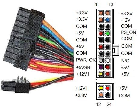
. (Nvidia 2070 S) , , 600W, ~500W. – 650W . , , – . , . – , ~$300. , . , (PS_ON) (COM). .
Find OS bootloader
There are two types of motherboard firmware - BIOS (Basic Input Output System) on older machines and UEFI (Unified Extensible Firmware Interface) on newer ones. Windows 10 supports both and abstracts the differences between them. It is more correct to call UEFI an OS than a firmware, because it offers more features, for example, a rich graphical interface instead of a textual one, the presence of a mouse, more available memory, an improved security model and validation of OS files, interaction with hardware via API, instead of interrupts like in BIOS.

Sample BIOS monitor screen.
The BIOS program is stored on a separate chip connected to the South Bridge. This chip can be obtained and reflashed with a new program, in fact it is just a memory carrier, and not an independent microcomputer.

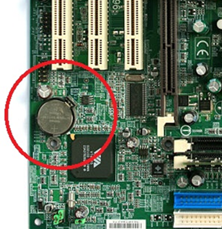
BIOS settings (system time, for example) are stored on another chip, which is usually located near a round battery, which is actually a lithium battery that recharges while the PC is running. It is called CMOS , which means Complementary Metal Oxide Semiconductor , and in Russian simply - CMOS, which is a complementary metal-oxide-semiconductor structure .
First of all, the BIOS program checks the subsystems, this procedure is called POST - Power On Self Test. The test can be abbreviated or complete, it is set in the BIOS settings. To quote Wikipedia , what these tests include: An
abbreviated test includes:
- Checking the integrity of BIOS programs in ROM using a checksum.
- Detection and initialization of the main controllers, system buses and connected devices (graphics adapter, disk controllers, etc.), as well as the execution of programs included in the BIOS of devices and ensuring their self-initialization.
- Determining the size of the RAM and testing the first segment (64 kilobytes).
Full regulations for POST:
- Checking all processor registers;
- Checking the checksum of the ROM;
- Checking the system timer and sound signaling port (for IBM PC - IC i8253 or equivalent);
- Direct memory access controller test;
- RAM regenerator test;
- Test of the lower RAM area for projecting resident programs in the BIOS;
- Loading resident programs;
- Standard graphics adapter test (VGA or PCI-E);
- RAM test;
- Test of main input devices (NOT keypads);
- CMOS test
- Test of the main LPT / COM ports;
- Test of floppy disk drives (floppy disk drives);
- Test of hard disk drives (HDD);
- Self-diagnostics of BIOS functional subsystems;
- Transferring control to the bootloader.
This test may reveal a malfunction, such as a non-working video card or keyboard. Since the monitor screen may not work, test results are reported as a series of beeps of different heights. What exactly they mean should be seen in the documentation for the motherboard. Older computers often beep during startup - this is the BIOS program reporting the test results. Sometimes an additional indicator can be used to show the error number.
If everything went well, the BIOS starts the process of searching for the OS bootloader. To do this, he begins to scan all hard drives connected to the motherboard. Data on physical disks is addressed in units called a sector , usually 512 bytes, but the current standard is 4096 bytes. The Windows installer writes special program code and partition data to the very first sector on the disk. This sector is called Master Boot Record . The disk is divided into partitions, formatted with their own file system. Maximum 4 partitions, each of which can be extended (extended partition), such one can be recursively divided into 4 sections and theoretically their number is not limited. As soon as the BIOS finds the Master Boot Record, it reads the code from there and transfers control to it. This code alternately looks through the data on the partitions and finds the one that is marked as active, it contains the Windows bootloader code (This is not the partition with C: \ Windows \ System32!), This partition is called the system partition . As a rule, it takes up 100MB and is hidden from the user. The first sector of this section stores the boot code to which control is transferred. This is the volume boot sector , the code in it looks for the Bootmgr file , from which the Windows boot process begins. The Bootmgr file is created via a single link between Startup.com files andBootmgr.exe .
The processor starts its work in the mode called "Real" . This is a compatibility mode, in which the CPU works in the same way as the old 16-bit processors that did not have virtual memory support and worked directly with physical memory through a 20-bit address bus that allowed 1MB of memory to be addressed. Simple MS-DOS programs ran in this mode and had the .COM extension. The first thing Startup.com (Bootmgr) does is switch the processor to the "Protected" mode, where protection means the protection of processes from each other. In this mode, virtual memory and 32-bit addresses are supported, which can be used to address 4GB of RAM. The next step, Bootmgr fills in the virtual address table for the first 16MB of RAM and turns on translation from virtual addresses to physical ones. In this mode Windows works. Since at this stage the OS subsystems have not yet been created, Bootmgr has its own simple and incomplete implementation of the NTFS file system, thanks to which it finds a BCD file (Boot Configuration Data) , which stores the settings for the OS boot parameters. You can edit it using the BcdEdit.exe utility . These BCD settings can indicate that Windows was in hibernation state and then Bootmgr will start the programWinResume.exe , which reads the state from the Hyberfil.sys file into memory and restarts the drivers. If the BCD says there are multiple operating systems, then Bootmgr will display a list of them and ask the user to select. If there is one OS, then Bootmgr launches WinLoad.exe, this process does the main work of initializing Windows:
- Selects the appropriate Windows kernel version. You can think of it as Windows10.exe, even though it's actually called NtOsKrnl.exe. What versions are there? According to wikipedia:
- ntoskrnl.exe is a single-processor Windows kernel. without PAE support
- ntkrnlmp.exe (English NT Kernel, Multi-Processor version) - Windows multiprocessor kernel. without PAE support
- ntkrnlpa.exe — Windows PAE.
- ntkrpamp.exe — Windows PAE.
- HAL.dll (Hardware Abstraction Layer), CPU.
- vgaoem.fon
- , . National Language System.
- Loads the SYSTEM registry into memory, it contains information about the drivers to be loaded. Information about all drivers is located in HKLM \ SYSTEM \ CurrentControlSet \ Services \ . The drivers that need to be loaded have the start = SERVICE_BOOT_START (0) key. We will talk about the registry device in another article.
- Loads the file system driver for the partition on which the driver files are located.
- Loads drivers into memory, but does not initialize them yet due to circular dependencies.
- Prepares the CPU registers for the execution of the Windows kernel selected in the first step - NtOsKrnl.exe.
When the drivers are loaded, WinLoad checks their digital signatures and if they do not match, there will be a blue ( BSOD ) or green ( GSOD , for insider preview assemblies) "screen of death".

Run on UEFI
An example of a UEFI
BIOS boot screen has been around for over 30 years and in an effort to correct its flaws, Intel created the Intel Boot Initiative in 1998, later renamed EFI and donated to the EFI Forum in 2005. Disadvantages of BIOS:
• Works only in 16-bit mode
• Can only address 1Mb of RAM
• Often has compatibility problems
• MBR is limited to only four main disk partitions
• An OS disk cannot be more than 2.2Tb.
• Has very limited capabilities for validating the OS bootloader.
BIOS was replaced by UEFI, in fact it is a miniature OS that can run in both 32-bit and 64-bit. For compatibility, there is an option Compatibility Support Module, which is included in the settings and emulates the BIOS.
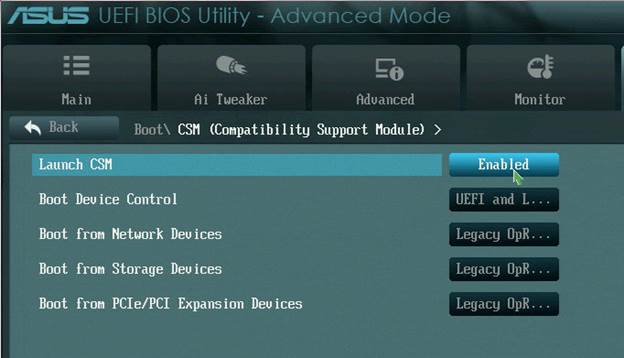
In UEFI, the boot occurs in the native bitness for the processor - 32 or 64, there is access to all memory, virtual memory is supported, Secure Boot is enabled and it is possible to run antimalware before the OS starts loading. OS boot order in UEFI:
- Firmware initialization and launch, chipset launch.
- POST test, similar to BIOS
- Loading EFI Drivers and Finding an EFI Eligible Boot Disk
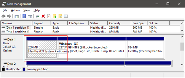
- Search for a folder named EFI. The UEFI specification requires that there be a partition for the EFI System Partition , formatted for the FAT file system, with a size of 100MB - 1GB or no more than 1% of the disk size. Each installed Windows has its own directory on this partition - EFI \ Microsoft .
- UEFI NVRAM ( ) .
- EFI/Microsoft/Boot/BootMgrFw.efi.
- BootMgrFw.efi BCD, BCD. WinLoad.efi, C:\Windows\System32\winload.efi.
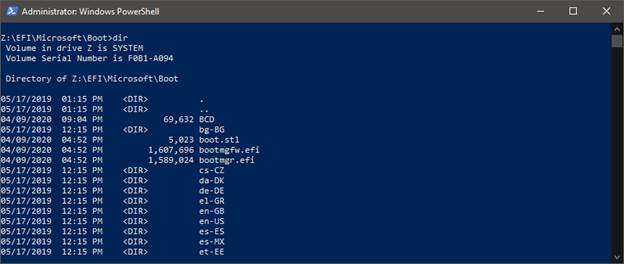
To view the contents of the EFI System Partition, open a console with admin rights (WinKey + X => Windows PowerShell (Admin)) and run the mountvol Z: / s, Z :, dir commands . CD - changes directory.
The main difference between the BootMgr and WinLoad components for UEFI from their BIOS counterparts is that they use the EFI API instead of BIOS interrupts, and the formats of the MBR BIOS and EFI System Partition boot partitions are very different.
Kernel initialization
Let me remind you that we are considering loading the PC in the context of the keyboard, so you should not focus on all the stages. It is necessary to understand where the keyboard is in this process, the stages important for understanding are highlighted .
At the previous stage, the WinLoad.exe / WinLoad.efi component was launched , which launches NtOsKrnl.exe by specifying boot parameters in the global variable nt! KeLoaderBlock (kernel mode memory is available to all processes) that WinLoad collected during its work. These include:
- Paths to System (Windows bootloader) and Boot ( C: \ Windows \ System32 ) directories.
- Pointer to virtual memory tables created by WinLoad
- A tree with a description of the connected hardware, it is used to create the HKLM \ HARDWARE registry key.
- A copy of the downloaded registry HKLM \ System
- Pointer to the list of loaded (but not initialized) drivers participating in Windows startup.
- Other information required for download.
The Windows kernel is initialized in two stages. Before that, the Hardware Abstraction Layer is initialized , which, among other things, configures the interrupt controllers for each CPU.
At the same stage, strings with messages for BSOD are loaded into memory, because at the time of a fall they may be inaccessible or damaged.
- First phase of kernel initialization:
- Executive – , , . Windows SKU (Stock Keeping Unit), Windows 10 SKU — Home, Pro, Mobile, Enterprise, Education.
- Driver Verifier, .
- , API (memory services), .
- (kernel debugger) .
- Windows.
- Object Manager – . – . handle table, HWND .
- Security Reference Monitor .
- Process Manager . Idle System ( “Windows10.exe” NtOsKrnl.exe), , .
- User-Mode Debugging Framework.
- Plug and Play Manager. PnP – , . .
- . 51 , :
- System (NtOsKrnl.exe) . . – 31.
- HAL .
- Windows Startup Screen, progress bar.
- Executive Semaphore, Mutex, Event, Timer.
- User-Mode Debugger .
- symbolic link \SystemRoot.
- NtDll.dll . Windows APIs.
- .
- Windows ALPC . named pipes Windows Communication Foundation .
- I/O Manager, . .
Windows Management Instrumentation Event Tracing for Windows ( Windows Performance Analyzer). . - SMSS.exe (Session Manager Sub System). , Windows.
– SMSS, CSRSS, WinInit
SMSS.exe is different from user processes, it is a native process and this gives it additional permissions. SMSS.exe works with the kernel bypassing the Windows API, it uses what is called the Native API . Windows API is a wrapper around the Native API. SMSS.exe first starts the Windows subsystem ( CSRSS.exe - Client Server Runtime Sub System ) and finishes initializing the registry.
The SMSS.exe process and threads are marked as critical, which means that if they terminate unexpectedly, for example due to an error, this will lead to a system crash. To communicate with subsystems, for example, an API call creating a new session, SMSS creates an ALPC port named SmApiPort... Environment variables are loaded from the registry, programs such as Check Disk (autochk.exe, these programs are written in the registry HKLM \ SYSTEM \ CurrentControlSet \ Control \ Session Manager \ BootExecute ) are launched . SMSS.exe is launched for every user session. Each session has its own global variables (message queue, for example) due to the virtual memory mechanism. Windows has thread, process and session contexts. Each SMSS.exe starts its own instance of the subsystem, at the moment it is only CSRSS.exe (Windows), in the past, OS / 2 (os2ss.exe) and POSIX (psxss.exe) operating systems were supported, but this idea was not successful. The very first SMSS.exe goes to sleep waiting for the WinInit.exe process. The rest of the instances instead create a WinLogon process that displays the login UI.
WinInit.exe initializes subsystems for creating a graphical shell - Windows Station and desktops , this is not the desktop that you see, this is a different Windows concept. Then it starts the processes:
- Services.exe - Services Control Manager (SCM) starts services and drivers marked as AutoStart. Services are started in svchost.exe processes . There is a utility called tlist.exe that, when run with the tlist.exe -s parameter, will print to the console the names of the services in each of the svchost.exe.
- LSASS.exe - Local System Authority.
- LSM.exe - Local Session Manager.
WinLogon.exe - Loads credential providers , which can be password, Smartcard, PIN, Hello Face. It spawns the LogonUI.exe process , which shows the user an interface for authentication, and then validates the entered data (login and password, PIN).
If everything went well, then WinLogon starts the process specified in the registry key HKLM \ SOFTWARE \ Microsoft \ Windows NT \ CurrentVersion \ WinLogon \ Userinit . By default, this is the UserInit.exe process , which:
- Runs scripts specified in the registries:
- HKCU \ Software \ Policies \ Microsoft \ Windows \ System \ Scripts
- HKLM \ SOFTWARE \ Policies \ Microsoft \ Windows \ System \ Scripts
- User Profile Quota, %SystemRoot%\System32\Proquota.exe
- Windows, Explorer.exe. :
- HKCU\Software\Microsoft\Windows NT\CurrentVersion\Winlogon\Shell
- HKLM\SOFTWARE\Microsoft\Windows NT\CurrentVersion\Winlogon\Shell
WinLogon notifies the Network Provider about the logged in user, to which he restores and connects the system disks and printers stored in the registry. The Network Provider is the mpr.dll file from the system folder, which is hosted by the svchost.exe process , i.e. Windows service.
The process tree looks like this, on it you can see who created whom (not all processes are shown, it may differ slightly from the latest versions of Windows).
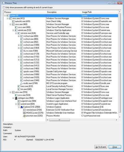
Where is the keyboard here?
During startup, the Windows kernel reads information about the system bus controller from the registry, as a rule, this is the PCI bus (less often MSI), I / O port controllers, including USB, PS / 2, are connected to it. Information about it is recorded during Windows installation. The system loads a driver for it and recursively bypasses all ports, also loading its own driver for each of them. Drivers can be combined into driver nodes , for example a keyboard driver will be connected to a PS2 port driver. But the USB port is more complicated - first the port driver, then the driver for working with the HID protocol, and only then the keyboard.
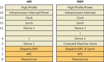
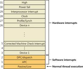
Each port is controlled by its own chip, which monitors the connection, receives / sends signals between the CPU and the device. If the South Bridge chipset is not built into the CPU, as is often done in laptops, but exists as a separate chip on the motherboard, then it would be more correct to say: the signal between the South Bridge and the port controller. The control port chip has a dedicated line with an interrupt controller (PIC or APIC), through which it can ask the CPU to pay attention to itself, for example, read data from the keyboard (PS / 2 port, USB is a different story). Since the OS has loaded a driver for the port, it can issue commands to it, read and send data. In our example, the driver was loaded from C: \ Windows \ System32 \ i8042prt.sys . Let's remember the previous article . In older computers with PIC on a chipIntel 8259 had 15 interrupt lines, where the keyboard was connected to the IRQ1 pin, the IRQ0 timer, and the mouse to IRQ12, which was actually the fifth leg of the second 8259 chip, which multiplexed its interrupts through the IRQ2 pin of the first controller. Modern PICs can have 255 pins for interrupt signals. During boot, the OS programs the APIC / PIC to return a certain number when, say, an interrupt arrives from the keyboard or USB port, and by this number the CPU finds the function to be executed in the interrupt vector table . Interrupt number is determined by HAL and Plug'n'Play Manager... The interrupt controller looks for a signal on its pins in a certain order, for example, in an infinite loop, it checks the voltage on pins from 1 to MAX_PIN. This order determines the priority, for example, the keyboard will be seen before the mouse, and the timer before the keyboard. In order not to depend on the peculiarities of the interrupt controllers, Windows abstracts the concept of IRQ (Interrupt Request) in IRQL (Interrupt Request Level) . If the interrupt controller has at least 15 or 255 lines, they will all be mapped to 32 IRQL for x86 and 15 IRQL for x64 and IA64.
 |
 |
- High - When the system crashes, it is usually a call to the KeBugCheckEx function.
- Power Fail - not used. It was originally designed for Windows NT.
- Interprocessor Interrupt – CPU , TLB cache, system shutdown, system crash (BSOD).
- Clock – , .
- Profile – real-time clock (local APIC-timer) kernel-profiling .
- Device 1 … Device N – I/O. , DPC (Deferred Procedure Call), . Dispatch DPC
- Dispatch DPC — .
- APC — Asynchronous Procedure Call. WaitForSingleObject, Sleep .
- Passive/Low — User Mode.
If you've always programmed in user mode, you have never heard of IRQL, because all user programs are executed with a Passive / Low (0) priority. As soon as an event occurs with b about lshim priority level (keyboard events, the thread scheduler timer), the processor saves the state of the interrupted thread, which is a CPU register values, and calls the dispatcher interrupt ( the interrupt dispatcher , just a function), which raises IRQL priority via the KeRaiseIrql API in the HAL and calls directly the interrupt's service routine itself . After that, the CPU IRQL is lowered to the previous level through the KeLowerIrql functionand the interrupted thread starts processing from the same place where it was interrupted. The thread scheduler is based on this mechanism . It sets a timer that, at a certain interval (time slice), generates an interrupt with a DPC / Dispatch (2) priority and, in its interrupt's service routine, according to a certain algorithm, assigns a new thread to execution.
The IRQL mechanism is implemented at the software level in the Hardware Abstraction Layer ( HAL.dll ), not hardware. Windows systems have a bus driver), which determines the presence of devices connected to the buses - PCI, USB, etc. and the interrupt numbers that can be assigned to each device. The bus driver communicates this information to the Plug and play manager, which already decides which interrupt numbers to assign to each device. Further, the interrupt arbiter within the PnP Mgr ( PnP interrupt arbiter ) establishes links between IRQ and IRQL.
When a keyboard interrupt arrives, any thread currently executing (this could be your program) is assigned to handle it. Interrupt dispatcher raises the CPU IRQL priority to one of the Device1-DeviceN levels . After that, the virtual memory manager will not be able to find the page if it is not loaded into RAM (will not be able to process Page Fault), the thread scheduler will not be able to interrupt the execution because they all run at a lower IRQL. The main task of the keyboard driver at this moment is to read the received data and save it for further processing. Data is written to an object of type _DPC ( Deferred Procedure Call ), which is saved to the list of the DPC stream (something like std :: list <DPC> , in the OS kernel, instead of arrays, linked lists are used). As soon as interrupts from all external devices are processed, the IRQL of the thread is lowered to the DPC level in which deferred procedures (DPC) are processed. The keyboard DPC handler code calls a function from the keyboard driver Kbdclass.sys :
VOID KeyboardClassServiceCallback(
  _In_    PDEVICE_OBJECT       DeviceObject,
  _In_    PKEYBOARD_INPUT_DATA InputDataStart,
  _In_    PKEYBOARD_INPUT_DATA InputDataEnd,
  _Inout_ PULONG               InputDataConsumed
);
So, the keyboard driver (kbdclass.sys) receives data from the port (USB, PS2) through an interrupt and writes them through WriteFile , a component inside the Windows kernel wakes up, reads them using the ReadFile API and adds messages from the keyboard to the queue. File APIs can be used to read data from drivers. From this moment, the processing of data by the Windows input stack begins, more about this in the next article.
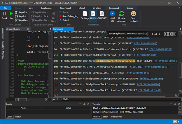
If you have a PC with a PS2 port and know how to use WinDbg in kernel mode, you can easily find a keyboard interrupt handler by typing ! Idt , which will display the entire interrupt vector table.... Interruption wedges itself into the course of the program, the word vector here means the direction, the direction of program execution. WinDbg was made specifically for Windows debugging, the most recent version is called WinDbgX. It has a text-based interface that scares away people accustomed to Visual Studio, but provides many more options, in particular, script execution. The purple PS2 port interrupt is highlighted in red. The function that handles it is called I8042KeyboardInterruptService , which is located in the i8042prt.sys file.
BOOLEAN
I8042KeyboardInterruptService(
  IN  PKINTERRUPT Interrupt,
  IN  PVOID Context
  );

Routine Description:

    This is the interrupt service routine for the keyboard device when
    scan code set 1 is in use.

Arguments:

    Interrupt - A pointer to the interrupt object for this interrupt.

    Context - A pointer to the device object.

Return Value:

    Returns TRUE if the interrupt was expected (and therefore processed);
    otherwise, FALSE is returned.
Now the question is, where does the interrupt handler get its argument from? Who is transmitting it? After all, the CPU knows nothing about it. If you put in her breakpoint, it was even more surprised to see a few features higher on the stack:
0: kd> kC
# of Call Site
00 i8042prt I8042KeyboardInterruptService!
01 nt KiCallInterruptServiceRoutine!
02 nt KiInterruptSubDispatch!
03 nt KiInterruptDispatch!
04 nt KiIdleLoop!
The explanation is simple - it is not the function stored in the processor's IDT register . What you see in the picture above are actually objects of type _KINTERRUPT... The interrupt table contains a special assembly code (nt! KiIdleLoop) that knows how to find the object describing the interrupt in memory. What is interesting about it?
- .
- i8042prt!I8042KeyboardInterruptService, PS2 IN AL, 0x60 – 0x60 AL.
- dispatcher – №2 .
- CPU. CPU , .
- . , Windows . IRQL (Interrupt Request Level) – IRQ.
As soon as the keyboard interrupt handler is called, it will notify the keyboard driver of the received data, after which the OS kernel will be notified, which, after processing the data, will send them further along the input stack, where they can be delivered to the application that will respond to them, or before that to the handler languages (Asian characters, auto-correction, auto-complete).
The OS kernel does not directly interact with the keyboard driver; Plug'n'Play Manager is used for this purpose. This component provides the IoRegisterPlugPlayNotification API that will call the provided callback function when a device is added or removed.
A few words about USB
Familiarization with the operation of the USB port would require a separate article describing its operation, plus a description of HID data processing on Windows. This would complicate things a lot, and there are already good articles on the topic, so the PS2 is a perfect example because of its simplicity.
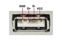
USB was created as a universal port for all devices, be it a keyboard, a camera, a scanner, a game wheel with pedals, a printer, etc. In addition, it supports nesting of ports - USB motherboard => monitor with USB => keyboard with USB to which a mouse is connected, flash drive and the USB hub to which the hard drive is connected. Taking a look at the USB 2.0 pins, you will see that they are not designed for the transfer of any specific data, like the PS2. There are only four of them - a twisted pair for transmitting data bits, plus and minus power.

USB 2.0
cable leads to USB 3.0 faster with five additional pins. As you can see, there is no CLOCK line for synchronization, so the data transfer logic is more complicated. Left USB 2.0 and right USB 3.0 for comparison.
 |
 |
First of all, the connected device must tell about itself, for this it sends several data structures, which indicate the device ID and manufacturer ID by which the Plug'n'Play manager can find information in the registry, load and connect drivers. USB devices are passive, i.e. the host must check for the presence of data itself at a certain interval. The polling rate and data packet size are specified in one of the USB device descriptors. The maximum packet size is 64 bytes, which is more than enough information about keystrokes.
Windows has built-in HID support, it is not as simple as linking a PS2 port driver to a keyboard driver, because the HID driver must be able to handle all the scripts supported by the protocol. Regardless of the data provider - PS2, USB or Remote Desktop ports or a virtual machine - at the very top of the driver node there will be Kbdclass, from which the OS kernel will receive information. The keyboard attachment notification will be processed through Plug'n'Play Manager , so it doesn't matter to the Windows kernel which port or device data source is used.
Part 1 - OS and Computer Basics
Part 2 - How the motherboard and keyboard work through the PS2 port