This is my first article on Habré, so I ask you not to throw heavy objects. Thanks in advance.
Let's start with the background. Once upon a time I had to switch to ST ARM microcontrollers. This was due to the fact that PIC and AVR were already in short supply and wanted new adventures. From those available in bakery stores and a large number of articles on "quick start", the choice fell on the STM32F100.
I am used to working at IAR. Yes, there are other IDEs, but the IAR feature is enough for me: a relatively convenient editor, not a bad debugger, and it is quite convenient to work with registers during debugging.
When I tried to make the first project I was disappointed - CMSIS! Anyone else, but for me it was (and remains) horror: a lot of beeches, long and incomprehensible structures for me. It was not interesting to delve into all this. I tried to compile a couple of examples and realized that this is not our method.
Are there no other options? There is. The one built into the IAR: iostm32f10xx4.h and similar include. Not bad at all:
RCC_APB2ENR_bit.ADC1EN = 1; // ADCAll that remained was to stuff it into classes and use it. And so he did. After some time, it took to make the code for STM32f4xx. And here again an ambush - there are no includists. What to do? - write yourself. I analyzed the existing self-written libraries and decided to do a little differently. This is what the story will be about.
Start
I will not talk about installing IAR and drivers for the debugger. there is nothing new here. I have IAR 8 with a 32kB code limit. The STM32F103 controller installed on the plue pill board is selected for operation.
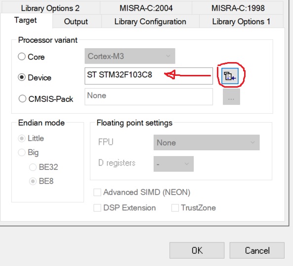
Launch IAR, create a c ++ project, select the desired controller.
The next step is to study the documentation. We will be interested in the Reference manual RM0008. The main thing is to read carefully.
In general, when I taught my employees to program controllers, I gave the task - to turn on the LED (connected to the controller leg), use a debugger, edit registers and read the documentation.
RCC module. Tucking
This module is usually forgotten. They remember only when it is impossible to blink the LED.
Remember! To turn on any peripherals, you need to apply clock pulses to it! You can't do without it.
The I / O ports sit on the APB2 bus. We find in the documentation a register for controlling the clocking of this bus, this is RCC_APB2ENR:

To enable clocking of port C (the LED is just soldered to PC13), you need to write one to the IOPCEN bit.
Now we will find the address of the register RCC_APB2ENR. Its offset is 0x18, the base address for the RCC registers is 0x40021000.
To make it convenient to work with bits, let's create a structure:
typedef struct
{
  uint32_t  AFIOEN         : 1;
  uint32_t                 : 1;
  uint32_t  IOPAEN         : 1;
  uint32_t  IOPBEN         : 1;
  uint32_t  IOPCEN         : 1;
  uint32_t  IOPDEN         : 1;
  uint32_t  IOPEEN         : 1;
  uint32_t                 : 2;
  uint32_t  ADC1EN         : 1;
  uint32_t  ADC2EN         : 1;
  uint32_t  TIM1EN         : 1;
  uint32_t  SPI1EN         : 1;
  uint32_t                 : 1;
  uint32_t  USART1EN       : 1;
  uint32_t                 :17;
} RCC_APB2ENR_b;
In order not to suffer later, we will immediately list all the register addresses:
enum AddrRCC
{
  RCC_CR          = 0x40021000,
  RCC_CFGR        = 0x40021004,
  RCC_CIR         = 0x40021008,
  RCC_APB2RSTR    = 0x4002100C,
  RCC_APB1RSTR    = 0x40021010,
  RCC_AHBENR      = 0x40021014,
  RCC_APB2ENR     = 0x40021018,
  RCC_APB1ENR     = 0x4002101C,
  RCC_BDCR        = 0x40021020,
  RCC_CSR         = 0x40021024
};
now it remains to write the code to enable the peripherals:
static void EnablePort(uint8_t port_name)
{
  volatile RCC_APB2ENR_b* apb2enr = reinterpret_cast<RCC_APB2ENR_b*>(RCC_APB2ENR);
  switch (port_name)
  {
    case 'A': apb2enr->IOPAEN = 1; break;
    case 'a': apb2enr->IOPAEN = 1; break;
    case 'B': apb2enr->IOPBEN = 1; break;
    case 'b': apb2enr->IOPBEN = 1; break;
    case 'C': apb2enr->IOPCEN = 1; break;
    case 'c': apb2enr->IOPCEN = 1; break;
    case 'D': apb2enr->IOPDEN = 1; break;
    case 'd': apb2enr->IOPDEN = 1; break;
    case 'E': apb2enr->IOPEEN = 1; break;
    case 'e': apb2enr->IOPEEN = 1; break;
  }
}
When working with registers, do not forget about volatile , otherwise, after optimization by the compiler, we will look for errors for a long time and scold the compiler developers.
We do the same to enable clocking of other peripherals.
As a result, we got the following class (not everything is listed):
STM32F1xx_RCC.h
#pragma once
#include "stdint.h"
namespace STM32F1xx
{
  class RCC
  {
  protected:
    enum AddrRCC
    {
      RCC_CR          = 0x40021000,
      RCC_CFGR        = 0x40021004,
      RCC_CIR         = 0x40021008,
      RCC_APB2RSTR    = 0x4002100C,
      RCC_APB1RSTR    = 0x40021010,
      RCC_AHBENR      = 0x40021014,
      RCC_APB2ENR     = 0x40021018,
      RCC_APB1ENR     = 0x4002101C,
      RCC_BDCR        = 0x40021020,
      RCC_CSR         = 0x40021024
    };

    typedef struct {
      uint32_t  HSION          : 1;
      uint32_t  HSIRDY         : 1;
      uint32_t                 : 1;
      uint32_t  HSI_TRIM       : 5;
      uint32_t  HSI_CAL        : 8;
      uint32_t  HSEON          : 1;
      uint32_t  HSERDY         : 1;
      uint32_t  HSEBYP         : 1;
      uint32_t  CSSON          : 1;
      uint32_t                 : 4;
      uint32_t  PLLON          : 1;
      uint32_t  PLLRDY         : 1;
      uint32_t                 : 6;
    } RCC_CR_b;

    typedef struct {
      uint32_t  SW             : 2;
      uint32_t  SWS            : 2;
      uint32_t  HPRE           : 4;
      uint32_t  PPRE1          : 3;
      uint32_t  PPRE2          : 3;
      uint32_t  ADC_PRE        : 2;
      uint32_t  PLLSRC         : 1;
      uint32_t  PLLXTPRE       : 1;
      uint32_t  PLLMUL         : 4;
      uint32_t  USBPRE         : 1;
      uint32_t                 : 1;
      uint32_t  MCO            : 3;
      uint32_t                 : 5;
    } RCC_CFGR_b;

    typedef struct
    {
      uint32_t  TIM2EN         : 1;
      uint32_t  TIM3EN         : 1;
      uint32_t  TIM4EN         : 1;
      uint32_t                 : 8;
      uint32_t  WWDGEN         : 1;
      uint32_t                 : 2;
      uint32_t  SPI2EN         : 1;
      uint32_t                 : 2;
      uint32_t  USART2EN       : 1;
      uint32_t  USART3EN       : 1;
      uint32_t                 : 2;
      uint32_t  I2C1EN         : 1;
      uint32_t  I2C2EN         : 1;
      uint32_t  USBEN          : 1;
      uint32_t                 : 1;
      uint32_t  CANEN          : 1;
      uint32_t                 : 1;
      uint32_t  BKPEN          : 1;
      uint32_t  PWREN          : 1;
      uint32_t                 : 3;
    } RCC_APB1ENR_b;

    typedef struct
    {
      uint32_t  AFIOEN         : 1;
      uint32_t                 : 1;
      uint32_t  IOPAEN         : 1;
      uint32_t  IOPBEN         : 1;
      uint32_t  IOPCEN         : 1;
      uint32_t  IOPDEN         : 1;
      uint32_t  IOPEEN         : 1;
      uint32_t                 : 2;
      uint32_t  ADC1EN         : 1;
      uint32_t  ADC2EN         : 1;
      uint32_t  TIM1EN         : 1;
      uint32_t  SPI1EN         : 1;
      uint32_t                 : 1;
      uint32_t  USART1EN       : 1;
      uint32_t                 :17;
    } RCC_APB2ENR_b;

    typedef struct {
      uint32_t  DMAEN          : 1;
      uint32_t                 : 1;
      uint32_t  SRAMEN         : 1;
      uint32_t                 : 1;
      uint32_t  FLITFEN        : 1;
      uint32_t                 : 1;
      uint32_t  CRCEN          : 1;
      uint32_t                 :25;
    } RCC_AHBENR_r;

  public:
    static void EnablePort(uint8_t port_name)
    {
      volatile RCC_APB2ENR_b* apb2enr = reinterpret_cast<RCC_APB2ENR_b*>(RCC_APB2ENR);
      switch (port_name)
      {
        case 'A': apb2enr->IOPAEN = 1; break;
        case 'a': apb2enr->IOPAEN = 1; break;
        case 'B': apb2enr->IOPBEN = 1; break;
        case 'b': apb2enr->IOPBEN = 1; break;
        case 'C': apb2enr->IOPCEN = 1; break;
        case 'c': apb2enr->IOPCEN = 1; break;
        case 'D': apb2enr->IOPDEN = 1; break;
        case 'd': apb2enr->IOPDEN = 1; break;
        case 'E': apb2enr->IOPEEN = 1; break;
        case 'e': apb2enr->IOPEEN = 1; break;
      }
    }

    static void DisablePort(char port_name)
    {
      volatile RCC_APB2ENR_b* apb2enr = reinterpret_cast<RCC_APB2ENR_b*>(RCC_APB2ENR);
      switch (port_name)
      {
        case 'A': apb2enr->IOPAEN = 0; break;
        case 'a': apb2enr->IOPAEN = 0; break;
        case 'B': apb2enr->IOPBEN = 0; break;
        case 'b': apb2enr->IOPBEN = 0; break;
        case 'C': apb2enr->IOPCEN = 0; break;
        case 'c': apb2enr->IOPCEN = 0; break;
        case 'D': apb2enr->IOPDEN = 0; break;
        case 'd': apb2enr->IOPDEN = 0; break;
        case 'E': apb2enr->IOPEEN = 0; break;
        case 'e': apb2enr->IOPEEN = 0; break;
      }
    }

    static void EnableAFIO()
    {
      volatile RCC_APB2ENR_b* apb2enr = reinterpret_cast<RCC_APB2ENR_b*>(RCC_APB2ENR);
      apb2enr->AFIOEN = 1;
    }

    static void DisableAFIO()
    {
      volatile RCC_APB2ENR_b* apb2enr = reinterpret_cast<RCC_APB2ENR_b*>(RCC_APB2ENR);
      apb2enr->AFIOEN = 0;
    }

    static void EnableI2C(int PortNumber)
    {
      switch (PortNumber)
      {
        case 1:
        {
          volatile RCC_APB1ENR_b* apb1enr = reinterpret_cast<RCC_APB1ENR_b*>(RCC_APB1ENR);
          apb1enr->I2C1EN = 1;
          break;
        }
        case 2:
        {
          volatile RCC_APB1ENR_b* apb1enr = reinterpret_cast<RCC_APB1ENR_b*>(RCC_APB1ENR);
          apb1enr->I2C2EN = 1;
          break;
        }

      }
    }

    static void EnableUART(int PortNumber)
    {
      switch (PortNumber)
      {
        case 1:
        {
          volatile RCC_APB2ENR_b* apb2enr = reinterpret_cast<RCC_APB2ENR_b*>(RCC_APB2ENR);
          apb2enr->USART1EN = 1;
          break;
        }
        case 2:
        {
          volatile RCC_APB1ENR_b* apb1enr = reinterpret_cast<RCC_APB1ENR_b*>(RCC_APB1ENR);
          apb1enr->USART2EN = 1;
          break;
        }
        case 3:
        {
          volatile RCC_APB1ENR_b* apb1enr = reinterpret_cast<RCC_APB1ENR_b*>(RCC_APB1ENR);
          apb1enr->USART3EN = 1;
          break;
        }

      }
    }

    static void DisableUART(int PortNumber)
    {
      switch (PortNumber)
      {
        case 1:
        {
          volatile RCC_APB2ENR_b* apb2enr = reinterpret_cast<RCC_APB2ENR_b*>(RCC_APB2ENR);
          apb2enr->USART1EN = 0;
          break;
        }
        case 2:
        {
          volatile RCC_APB1ENR_b* apb1enr = reinterpret_cast<RCC_APB1ENR_b*>(RCC_APB1ENR);
          apb1enr->USART2EN = 0;
          break;
        }
        case 3:
        {
          volatile RCC_APB1ENR_b* apb1enr = reinterpret_cast<RCC_APB1ENR_b*>(RCC_APB1ENR);
          apb1enr->USART3EN = 0;
          break;
        }
      }
    }

    static void EnableSPI(int PortNumber)
    {
      switch (PortNumber)
      {
        case 1:
        {
          volatile RCC_APB2ENR_b* apb2enr = reinterpret_cast<RCC_APB2ENR_b*>(RCC_APB2ENR);
          apb2enr->SPI1EN = 1;
          break;
        }
        case 2:
        {
          volatile RCC_APB1ENR_b* apb1enr = reinterpret_cast<RCC_APB1ENR_b*>(RCC_APB1ENR);
          apb1enr->SPI2EN = 1;
          break;
        }
      }
    }

    static void DisableSPI(int PortNumber)
    {
      switch (PortNumber)
      {
        case 1:
        {
          volatile RCC_APB2ENR_b* apb2enr = reinterpret_cast<RCC_APB2ENR_b*>(RCC_APB2ENR);
          apb2enr->SPI1EN = 0;
          break;
        }
        case 2:
        {
          volatile RCC_APB1ENR_b* apb1enr = reinterpret_cast<RCC_APB1ENR_b*>(RCC_APB1ENR);
          apb1enr->SPI2EN = 0;
          break;
        }
      }
    }

    static void EnableDMA()
    {
      volatile RCC_AHBENR_r* ahbenr = reinterpret_cast<RCC_AHBENR_r*>(RCC_AHBENR);
      ahbenr->DMAEN = 1;
    }

    static void DisableDMA()
    {
      volatile RCC_AHBENR_r* ahbenr = reinterpret_cast<RCC_AHBENR_r*>(RCC_AHBENR);
      ahbenr->DMAEN = 0;
    }
  };
}
Now you can attach a file in main.cpp and use:
#include "STM32F1xx_RCC.h"

using namespace STM32F1xx;

int main()
{
  RCC::EnablePort('c');
  return 0;
}
Now you can work with the ports. GPIO
Open the General-purpose and alternate-function I / Os section in the documentation. Find the Port bit configuration table:

The CNF [1: 0] bits set the port operation mode (analog input, digital input, output), the MODE [1: 0] bits correspond to the port operation speed in the output mode.
Let's take a look at the registers GPIOx_CRL and GPIOx_CRH (x = A, B, C, ...), you

can see that the bits go sequentially:
CNF [1: 0], MODE [1: 0]
then create constants with port modes
enum mode_e
{
  ANALOGINPUT             = 0,
  INPUT                   = 4,
  INPUTPULLED             = 8,

  OUTPUT_10MHZ            = 1,
  OUTPUT_OD_10MHZ         = 5,
  ALT_OUTPUT_10MHZ        = 9,
  ALT_OUTPUT_OD_10MHZ     = 13,

  OUTPUT_50MHZ            = 3,
  OUTPUT_OD_50MHZ         = 7,
  ALT_OUTPUT_50MHZ        = 11,
  ALT_OUTPUT_OD_50MHZ     = 15,

  OUTPUT_2MHZ             = 2,
  OUTPUT_OD_2MHZ          = 6,
  ALT_OUTPUT_2MHZ         = 10,
  ALT_OUTPUT_OD_2MHZ      = 14,

  OUTPUT                  = 3,
  OUTPUT_OD               = 7,
  ALT_OUTPUT              = 11,
  ALT_OUTPUT_OD           = 15
};
then the method for configuration will look like this:
// pin_number -
void Mode(mode_e mode)
{
  uint32_t* addr;
  if(pin_number > 7)
    addr = reinterpret_cast<uint32_t*>(GPIOA_CRH);
  else
    addr = reinterpret_cast<uint32_t*>(GPIOA_CRL);

  int bit_offset;
  if(pin_number > 7)
    bit_offset = (pin_number - 8) * 4;
  else
    bit_offset = pin_number * 4;

  uint32_t mask = ~(15 << bit_offset);
  *addr &= mask;
  *addr |= ((int)mode) << bit_offset;
}
now you can make more convenient methods for selecting a mode:
    void ModeInput()              { Mode(INPUT);         }
    void ModeAnalogInput()        { Mode(ANALOGINPUT);   }
    void ModeInputPulled()        { Mode(INPUTPULLED);   }
    void ModeOutput()             { Mode(OUTPUT);        }
    void ModeOutputOpenDrain()    { Mode(OUTPUT_OD);     }
    void ModeAlternate()          { Mode(ALT_OUTPUT);    }
    void ModeAlternateOpenDrain() { Mode(ALT_OUTPUT_OD); }
In the documentation, we find the addresses of the control registers for the ports and list them:
enum AddrGPIO
{
  PortA           = 0x40010800,
  GPIOA_CRL       = 0x40010800,
  GPIOA_CRH       = 0x40010804,
  GPIOA_IDR       = 0x40010808,
  GPIOA_ODR       = 0x4001080C,
  GPIOA_BSRR      = 0x40010810,
  GPIOA_BRR       = 0x40010814,
  GPIOA_LCKR      = 0x40010818,
  PortB           = 0x40010C00,
  PortC           = 0x40011000,
  PortD           = 0x40011400,
  PortE           = 0x40011800,
  PortF           = 0x40011C00,
  PortG           = 0x40012000
};
Long thought to use base address and offsets or absolute addresses. In the end, I stopped at the latter. This adds some overhead, but it's easier to find in memory during debugging.
Let's modernize the method:
if(pin_number > 7)
  addr = reinterpret_cast<uint32_t*>(GPIOA_CRH - PortA + PortAddr);
else
  addr = reinterpret_cast<uint32_t*>(GPIOA_CRL - PortA + PortAddr);
Perhaps someone will have an eye twitch, but I haven’t come up with a more beautiful one yet.
To transfer the leg to the desired logical state, it is enough to write the corresponding bit in the ODRx register. For example, like this:
void Set(bool st)
{
  uint32_t* addr;
  addr = reinterpret_cast<uint32_t*>(GPIOA_ODR - PortA + PortAddr);

  if(st)
    *addr |= 1 << pin_number;
  else
  {
    int mask = ~(1 << pin_number);
    *addr &= mask;
  }
}
You can also use the GPIOx_BSRR registers to control the state.
By analogy, we make methods for reading the port state, methods for configuration and initialization (do not forget to enable clocking). As a result, we got the following class for working with ports:
STM32F1xx_Pin.h
#pragma once
#include <stdint.h>
#include "STM32F1xx_RCC.h"

namespace STM32F1xx
{
  class Pin
  {
  public:
    enum mode_e
    {
      ANALOGINPUT             = 0,
      INPUT                   = 4,
      INPUTPULLED             = 8,

      OUTPUT_10MHZ            = 1,
      OUTPUT_OD_10MHZ         = 5,
      ALT_OUTPUT_10MHZ        = 9,
      ALT_OUTPUT_OD_10MHZ     = 13,

      OUTPUT_50MHZ            = 3,
      OUTPUT_OD_50MHZ         = 7,
      ALT_OUTPUT_50MHZ        = 11,
      ALT_OUTPUT_OD_50MHZ     = 15,

      OUTPUT_2MHZ             = 2,
      OUTPUT_OD_2MHZ          = 6,
      ALT_OUTPUT_2MHZ         = 10,
      ALT_OUTPUT_OD_2MHZ      = 14,

      OUTPUT                  = 3,
      OUTPUT_OD               = 7,
      ALT_OUTPUT              = 11,
      ALT_OUTPUT_OD           = 15
    };

  private:
    enum AddrGPIO
    {
      PortA           = 0x40010800,
      GPIOA_CRL       = 0x40010800,
      GPIOA_CRH       = 0x40010804,
      GPIOA_IDR       = 0x40010808,
      GPIOA_ODR       = 0x4001080C,
      GPIOA_BSRR      = 0x40010810,
      GPIOA_BRR       = 0x40010814,
      GPIOA_LCKR      = 0x40010818,
      PortB           = 0x40010C00,
      PortC           = 0x40011000,
      PortD           = 0x40011400,
      PortE           = 0x40011800,
      PortF           = 0x40011C00,
      PortG           = 0x40012000
    };

  private:
    int   pin_number;
    int   PortAddr;

  public:
    Pin()                               { }
    Pin(char port_name, int pin_number) { Init(port_name, pin_number); }
    ~Pin()
    {
      Off();
      ModeAnalogInput();
    }
  public:
    void Init(char port_name, int pin_number)
    {
      this->pin_number = pin_number;
      RCC::EnablePort(port_name);
      switch (port_name)
      {
        case 'A': PortAddr = PortA; break;
        case 'a': PortAddr = PortA; break;
        case 'B': PortAddr = PortB; break;
        case 'b': PortAddr = PortB; break;
        case 'C': PortAddr = PortC; break;
        case 'c': PortAddr = PortC; break;
        case 'D': PortAddr = PortD; break;
        case 'd': PortAddr = PortD; break;
        case 'E': PortAddr = PortE; break;
        case 'e': PortAddr = PortE; break;
      }
    }

    void ModeInput()              { Mode(INPUT);         }
    void ModeAnalogInput()        { Mode(ANALOGINPUT);   }
    void ModeInputPulled()        { Mode(INPUTPULLED);   }
    void ModeOutput()             { Mode(OUTPUT);        }
    void ModeOutputOpenDrain()    { Mode(OUTPUT_OD);     }
    void ModeAlternate()          { Mode(ALT_OUTPUT);    }
    void ModeAlternateOpenDrain() { Mode(ALT_OUTPUT_OD); }

    void NoPullUpDown()
    {
      uint32_t* addr;
      if(pin_number > 7)
        addr = reinterpret_cast<uint32_t*>(GPIOA_CRH - PortA + PortAddr);
      else
        addr = reinterpret_cast<uint32_t*>(GPIOA_CRL - PortA + PortAddr);

      int bit_offset;
      if(pin_number > 7)
        bit_offset = (pin_number - 8) * 4;
      else
         bit_offset = pin_number * 4;

      int mask = ~((1 << 3) << bit_offset);
      *addr &= mask;
    }

    void Mode(mode_e mode)
    {
      uint32_t* addr;
      if(pin_number > 7)
        addr = reinterpret_cast<uint32_t*>(GPIOA_CRH - PortA + PortAddr);
      else
        addr = reinterpret_cast<uint32_t*>(GPIOA_CRL - PortA + PortAddr);

      int bit_offset;
      if(pin_number > 7)
        bit_offset = (pin_number - 8) * 4;
      else
        bit_offset = pin_number * 4;

      uint32_t mask = ~(15 << bit_offset);
      *addr &= mask;
      *addr |= ((int)mode) << bit_offset;
    }

    void Set(bool st)
    {
      uint32_t* addr;
      addr = reinterpret_cast<uint32_t*>(GPIOA_ODR - PortA + PortAddr);

      if(st)
        *addr |= 1 << pin_number;
      else
      {
        int mask = ~(1 << pin_number);
        *addr &= mask;
      }
    }

    void On()
    {
      uint32_t* addr;
      addr = reinterpret_cast<uint32_t*>(GPIOA_ODR - PortA + PortAddr);
      int bit_offset = pin_number;
      *addr |= 1 << bit_offset;
    }

    void Off()
    {
      uint32_t* addr;
      addr = reinterpret_cast<uint32_t*>(GPIOA_ODR - PortA + PortAddr);
      int bit_offset = pin_number;
      int mask = ~(1 << bit_offset);
      *addr &= mask;
    }

    bool Get()
    {
      uint32_t* addr = reinterpret_cast<uint32_t*>(GPIOA_IDR - PortA + PortAddr);
      int bit_offset = pin_number;
      int mask = (1 << bit_offset);
      bool ret_val = (*addr & mask);
      return ret_val;
    }
  };
};
Well, let's try:
#include "STM32F1xx_Pin.h"

using namespace STM32F1xx;

Pin led('c', 13);

int main()
{
  led.ModeOutput();
  led.On();
  led.Off();
  return 0;
}
We go through the debugger and make sure that the LED first lights up (after led.ModeOutput ();), then goes out (led.On ();) and lights up again (led.Off ();). This is because the LED is connected to the leg through the power line. Therefore, when the pin is low, the LED lights up.
Not great totals
In this article I have tried (I hope it succeeded) to show how you can simplify your life a little, make the code more readable. Or vice versa - how not to do it. Everyone will decide for himself.
It was possible to just write wrappers for CMSIS, but this is not interesting.
Thank you for your time. If you are interested in the sequel, let me know.