Introduction
Doom Eternal needs no separate introduction: it is a direct successor to Doom 2016, developed thanks to the seventh iteration of id Tech, id Software's internal engine. At one time, I was struck by the high quality of the visual component of Doom 2016, and the simplicity and elegance of technical solutions. In this respect, Doom Eternal surpasses its predecessor in many areas, and some of them are worthy of a detailed breakdown. In this analytical article I will try to discuss them all.
My analysis is inspired by hard Adrian Courrèges about Doom 2016 ( translation). In my opinion, such works provide a glimpse into approaches to solving some of the rendering problems of AAA projects and thus become excellent teaching materials. In this analysis, I plan to discuss general features and not dive too deeply into the intricacies of each render method and pass. In addition, some of the passages in Doom Eternal are almost identical to their counterparts in Doom 2016 and have already been disassembled in the work of Adrian Courrèges, so I can skip them.
I would like to mark in a special way the strictly teachingthe nature of the current article. I do not in any way endorse the reverse engineering of products for the purpose of intellectual property theft or other malicious intent. If you haven’t played Doom Eternal yet, you don’t have to worry: I’ve only covered the very beginning of the game, so you are not in danger of spoilers.
So let's get started.
With the release of id Tech 7, the engine's transition from OpenGL to the Vulkan API allowed developers to more effectively work with the features of the current generation of GPUs, such as bindless resources.
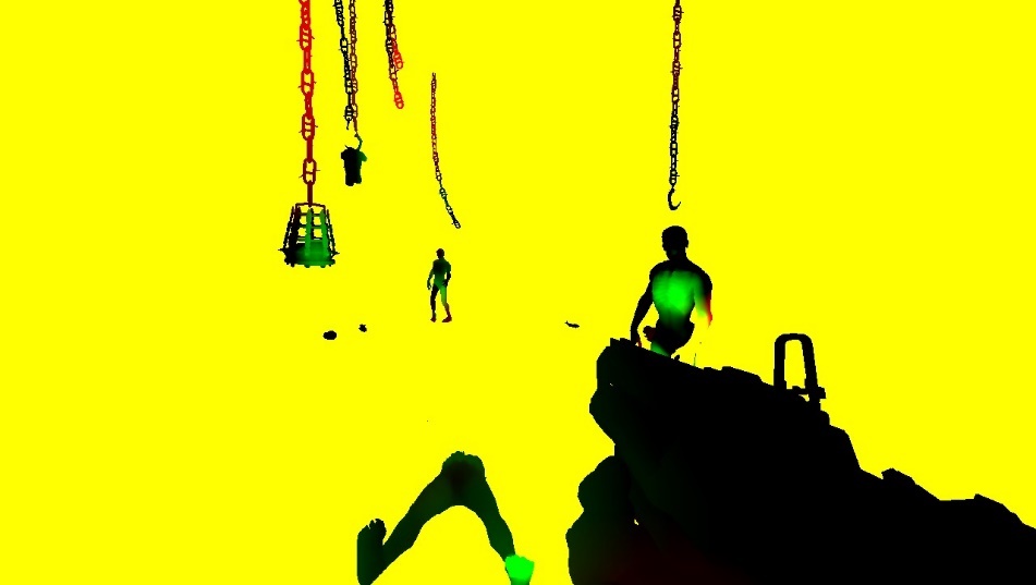
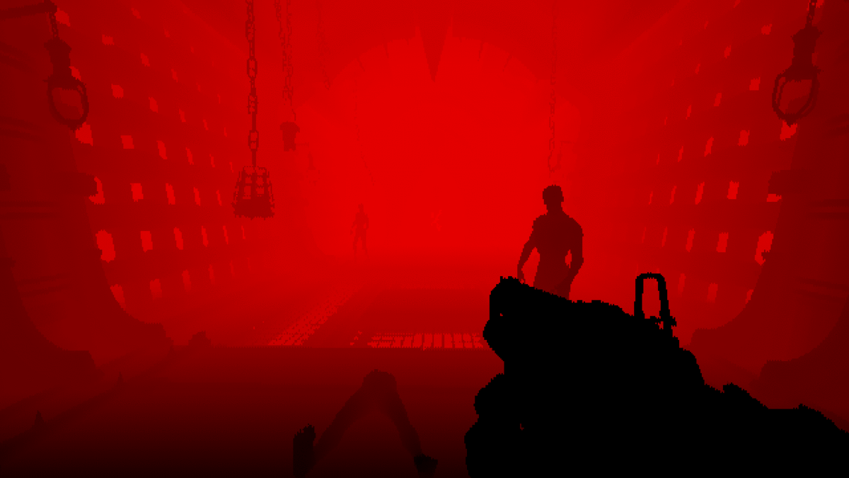
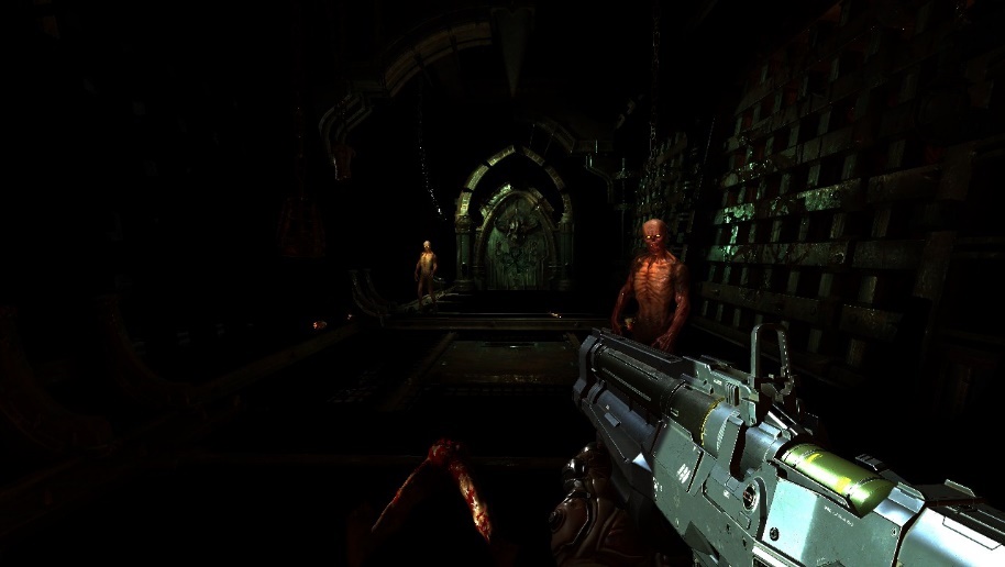
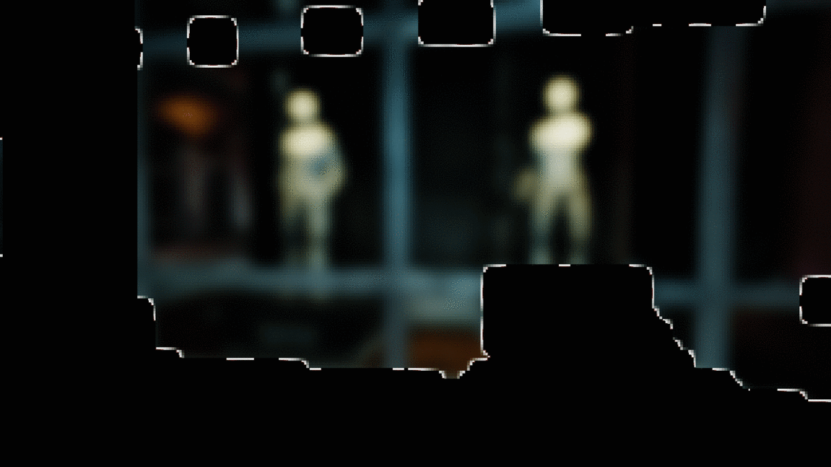
One frame in Doom Eternal

Above, we can see a section of the game close to the beginning: an interior with several opponents and volumetric lighting. By analogy with its predecessor, the rendering process in Doom Eternal is in charge of direct rendering , but if Doom 2016 is forced to render together with G-buffering of reflective surfaces, in our case the buffer is not used and rendering takes over all the tasks.
Moving away from megatextures
With the release of the game Rage, created on the id Tech 5 engine, the world got acquainted with the concept of implementing textures called "mega textures". This method is used in Doom 2016 and for each frame it renders a so-called "virtual texture" with information about visible textures. The virtual texture is analyzed in the next frame to determine which textures should be loaded from disk. However, megatextures have an obvious problem: as soon as the texture enters the field of view, it’s too late to load it, so the texture looks blurry in the first few frames after it appears. With the release of id Tech 7, the developers abandoned this method.
Skinning through the GPU
Usually, even before any textures and shading are drawn, the skinning is evaluated by the vertex shader. Skinning id Tech 7 is carried out in advance by a computational shader with writing the resulting vertices to the buffer. Thanks to this approach, the vertex shader no longer needs skinning data, and since it is no longer performed on each geometry pass, as a result, shader swaps happen less often.
The key difference between skinning in a compute shader and a vertex shader is writing the result to an intermediate buffer. As with the vertex shader, for each vertex, the compute shader thread receives a transform of each bone affecting the vertex. Then it changes the position of the vertex with each bone transformation and adds all the new positions according to the stored skin weight in the vertex. As a result, the vertex shader can use the result from the buffer to interpret it as a static mesh.
The link provides an excellent article on Compute Shader Skinning by János Turánszki.
It's also useful to note that Doom Eternal uses an interesting kind of caching - Alembic Cachecomparable to highly compressed back-playable video. These caches store baked animations to be issued and expanded during program execution. Citing the technical analysis of Digital Foundry , Alembic Cache is applied to a wide range of animations, from large-scale cinematic scenes to tiny tentacles on the floor. This approach is especially convenient for animations with complexities of implementation through skin animation, for example, for organics and tissue simulation. If you are interested in this technology, I recommend that you check out the Axel Gneiting presentation at Siggraph 2014 .
Shadow maps
The next step is shadow rendering, and at first glance id Tech 7 and its predecessor approach to generating their maps is no different.
As you can see below, the shadows are rendered into a large texture with a depth of 24 bits and a size of 4096 by 8196 pixels, varying in quality in places. The texture does not change between frames, and according to the presentation "Devil is in the Details" at Siggraph 2016, the static geometry is cached in the shadowmap to avoid redrawing it for every frame. The idea itself is simple: we don't need to update the shadows until there is movement in front of the light source, and thus we can declare a "cached" shadow map: a regular map with static geometry, since we assume that the geometry does not change ... If a dynamic object moves in the view cone, the "cached" shadow map is copied to the main one, and the dynamic geometry is redrawn on top of it. This approach allows not to redraw the entire scene in the cone of view every time it is updated. Naturally, if the light is shifted, the entire scene will have to be redrawn from scratch.
3x3 PCF sampling is used to smooth the edges of shadows when sampling the map. Since sunlight usually covers a significant portion of the environment, cascading shadow maps are used to better distribute quality.
For example, take a look at the atlas of shadow maps. The more significant the light, the larger the area on the screen or the closer the object is to the camera, the larger the selected segment of the atlas will be - this is necessary for increased detail. Such heuristics are dynamically evaluated.

Depth speed and pre-pass
Starting with the player's weapon, opaque, static, and dynamic geometries are rendered sequentially to the target depth. Usually, in order not to do unnecessary calculations of pixel shaders at a potential intersection of geometries, a preliminary pass of depth processing is performed with the addition of the result to the buffer. Since redrawing pixels as they intersect creates unnecessary recalculations and ultimately negatively affects performance, the importance of this approach becomes invaluable. With depth pre-pass, a direct illumination pixel shader can eliminate extra pixels by comparing them to a depth buffer before the actual computation, thereby saving valuable resources.

Player Weapons

Static Objects

Dynamic Objects
In the pre-pass, not only the depth is rendered, but also the target color. In dynamic geometry, speed is rendered through motion vectors, that is, the position of the current position subtracted from the pixel position in the previous frame. Since the motion is stored in the red and green channels of the 16-bit floating point render target, we only need to know the X and Y motion. This information is then used in post-processing to apply blur and re-projection of temporal anti-aliasing. Static geometry does not need motion vectors, since it "moves" only relative to the camera and its movement can be calculated from the movement of the camera itself. As you can see in the screenshot below, there isn't much movement in our scene.
Z-hierarchical depth
The next step is to generate a hierarchical depth buffer mip-chain: this chain is similar to a mip-map, but instead of averaging four adjacent pixels, it takes their maximum value. This approach is often used in graphics for a variety of tasks, such as speeding up reflections and discarding obstructed geometry. In our case, the mip chain is discarding lighting and decals, which we'll talk about later. Recently, mip generation has been carried out in one pass, with recording in several mip-s at once, but in Doom Eternal, recording is still carried out separately for each mip.
Mesh decals
So far, we have not had time to get acquainted with any major differences between the processes in Doom Eternal compared to Doom 2016, but grid decals fit into this category. These are small decals (bolts, grilles, bumps) that, like regular decals, can affect any surface properties (normal, roughness, color). However, a typical grid decal is assigned by artists during the development of the grid and, unlike the standard placement of decals in the environment, belongs to its own grid. Doom has relied heavily on decals in the past, and the current move to mesh decals has only increased the detail and flexibility of the graphics.
To achieve this benefit, the next geometry pass renders the IDs of each decal into an eight-bit texture. Further, when applying shadows, we sample the texture and through the identifiers we get the projection matrix associated with each call to draw. The matrix projects pixel coordinates from world space into texture space, and then these coordinates are used to sample the decal and merge it with the surface material. This technique is incredibly fast in its execution and opens up a wide scope for artists to work with a variety of decals. Since the IDs are rendered to an 8-bit texture, there can potentially be up to 255 decals on a single mesh.
The only condition for all this is that all decal textures are bound to processes when rendering meshes. With a completely unrelated rendering process, developers can link all decal textures at once and dynamically index them in the shader. Since the developers use this method to implement a few more tricks in the game, we'll talk more about the unrelated rendering process later.
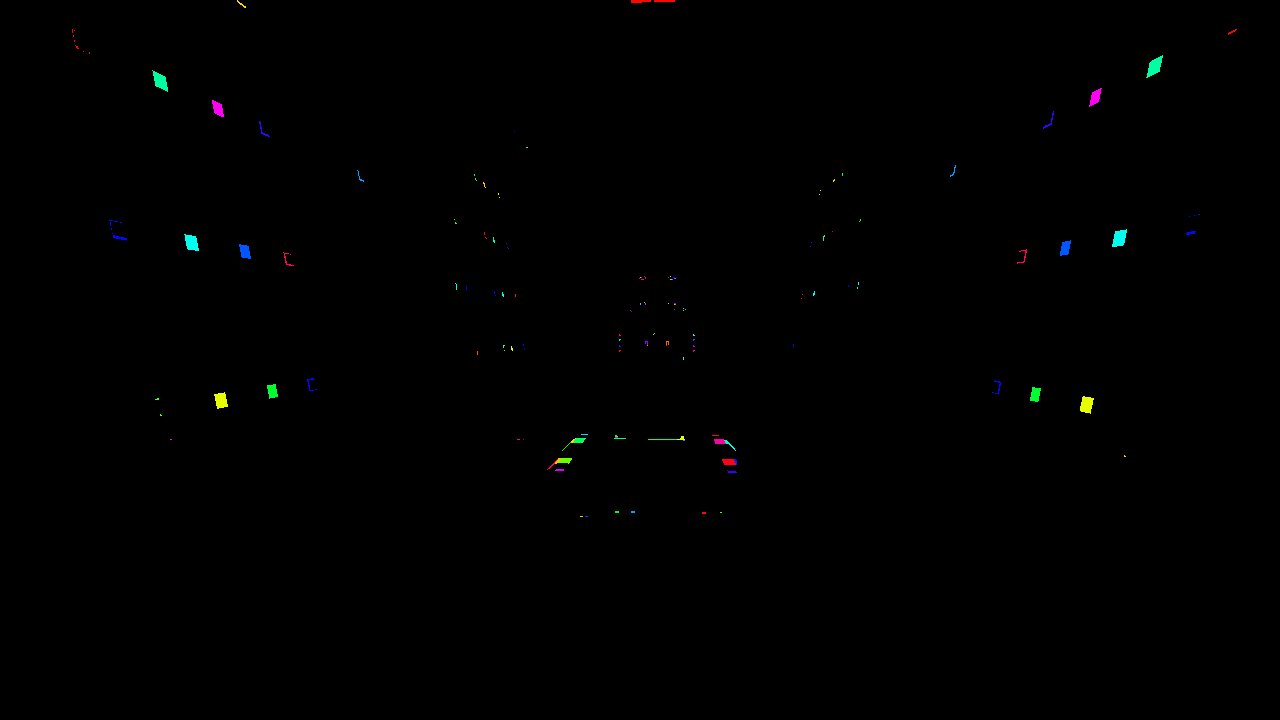
Below we can see the decal texture mesh. For visualization convenience, identifiers are colored in different colors.
Casting off lights and decals
The light in Doom Eternal is fully dynamic, and up to several hundred sources can hit the field of view at the same time. In addition, as we noted earlier, decals in the game are of great importance, for example, in the same Doom 2016, the number of decals exceeded thousands. All this requires a special approach to discarding excess, otherwise the performance will not withstand the severity of pixel shaders.
Doom 2016 used a processor-based version of cluster light rejection: the light and decals were collected into cone-shaped “froxels”, which were then read during shading by determining the cluster index from the pixel position. The size of each cluster was 256 pixels and was divided logarithmically into 24 segments to maintain a square shape. This technique was soon adopted by many other developers, and similar methods are found, for example, in Detroit: Become Human and Just Cause.
Considering the growing number of dynamic lighting sources (hundreds) and decals (thousands), the CPU clustering of the lighting drop in Doom Eternal was no longer enough, as the voxels were getting too coarse. As a result, the developers came up with a different approach for id Tech 7, and through computational shaders executed at various stages, they created a software rasterizer. First, the decals and light are linked into a hexahedron (hexagon) and transferred to a computational rasterizer, from where the vertices are projected into screen space. Then a second compute shader trims the triangles to the edges of the screen and assembles them into 256 by 256 pixels tiles. At the same time, by analogy with cluster discarding, individual elements of light sources and decals are recorded in froxels,after which the next computational shader performs a similar procedure for tiles 32 by 32 pixels. In each tile, elements that pass the depth test are marked in a bit field. The final computational shader translates the bitfields into a list of lights that are eventually used in the light pass. Interestingly, the element indices are still recorded in three-dimensional froxels of 256 by 256 pixels, similar to the cluster approach. In places with a significant interruption in depth, the minimum value of both the new list of lights and the old list of clustered sources is compared to determine the number of lights in each tile.which are ultimately used in the lighting pass. Interestingly, the element indices are still recorded in three-dimensional froxels of 256 by 256 pixels, similar to the cluster approach. In places with a significant interruption in depth, the minimum value of both the new list of lights and the old list of clustered sources is compared to determine the number of lights in each tile.which are ultimately used in the lighting pass. Interestingly, the element indices are still recorded in three-dimensional froxels of 256 x 256 pixels, similar to the cluster approach. In places with a significant interruption in depth, the minimum value of both the new list of lights and the old list of clustered sources is compared to determine the number of lights in each tile.
If you haven't dealt with traditional rasterization, such a rich description may not be clear to you. If you want to dive into the question in more detail, I recommend exploring the general principles of how such processes work, for example, Scratchapixel has a very good analysis of the topic .
The so-called "scopes" used to query game visibility are also discarded by this system. Since software rasterization for computational threads is a long process, the occupancy is very likely low, and therefore adding a few additional frames has almost no effect on performance. With this in mind, light is likely to be cast asynchronously, and thus the net impact on performance is minimal.
Blocking ambient light in screen space
Ambient occlusion is computed at half resolution in a fairly standard way: first, 16 random rays emanate from the position of each pixel in the hemisphere, and then using the depth buffer, the intersecting rays with the geometry are determined. The more rays cross the geometry, the larger the obstruction will be. This technique is called Screen Space Directional Occlusion, or SSDO, and a detailed description by Yuriy O'Donnell can be found here . Instead of the traditional storing of occlusion values in a single-channel texture, directional occlusion is stored in a three-component texture, and the resulting occlusion is defined through the dot product over the pixel normal.
Since the calculation is done at half resolution, the result is quite noisy. To improve quality with a depth buffer, a double-sided blur is applied. Ambient light blocking usually occurs at low frequencies, so blurring is usually not noticeable.

Opaque straight passage
In this passage, many of the elements finally fall into place. Unlike Doom 2016, everything here is rendered directly through several massive mega-shaders. There are supposedly about 500 processor states and a dozen descriptor layouts throughout the game. The player's weapons are rendered first, then dynamic objects, and then static objects. Please note that the order is not particularly important, because thanks to the depth prepass we have already received a depth buffer, and it can exclude pixels that do not correspond to the depth in advance.

Player weapons

Dynamic objects
First set of static objects
Second set of static objects
For most AAA game engines, shader graphs and static shader features allow developers to get creative with all sorts of materials and surfaces, and each material, each surface, leads to its own unique shader. As a result, we are faced with an incredible variety of shader permutations for all possible combinations of engine features. However, id Tech is very different from other AAA projects: it combines almost all materials and features into just a few massive mega-shaders. This approach allows GPUs to more tightly combine geometry, which in turn has a positive effect on performance. We will discuss this later.
Unbound resources
It is worth noting that the whole process of forming graphics contains the idea of "unrelated resources". This means that instead of binding the blur, reflections, roughness of the texture before each draw call, the entire list of textures in the scene is bound at once. The textures from the list are accessed dynamically in the shader through the indices passed to the shader by constants. Thus, through any call to draw, you can get any texture, which opens the way for many optimizations, one of which we will now talk about.

Dynamically merging draw calls
On top of a completely decoupled resource architecture, all geometry data is allocated from one large buffer . This buffer simply stores the offset of the entire geometry.
This is where idTech 7's most interesting technology comes into play: dynamic merging of draw calls.... It relies on a decoupled resource architecture and generalized vertex memory, and as a result, significantly reduces the number of draw calls and processor time. Before any rendering begins, the compute shader dynamically creates an “indirect” index buffer to efficiently merge geometries from unrelated meshes into a single indirect draw call. Without unrelated resources, call merging would not work because it works with geometries with mismatched material properties. In the future, it will be possible to use the dynamic index buffer again, both for the depth prepass and for the lighting prepass.
Reflections
The most common computational shader uses the raymarching algorithm to create screen space reflections. The algorithm emits a ray from the pixel into world space towards the reflection, which depends on the roughness of the reflecting surface. The same was the case in Doom 2016, where a small G-buffer was recorded as part of the forward pass. However, in Doom Eternal there is no longer any G-buffer, and even screen space reflections are calculated not in the computational shader separately, but immediately in the direct shader . It is interesting to know how such a deviation in the pixel shader affects performance, since it seems that at the expense of the increased load on the register, the developers were trying to reduce the number of render targets and, as a result, reduce the load on the memory bandwidth.
Often, when the screen space texture does not contain the necessary information, rendering artifacts appear in the corresponding effects. This is most often seen in screen-space reflections in cases where invisible reflective objects cannot be reflected. The problem is usually solved with the traditional approach, using static reflection cube maps as a backup.

But since mega-textures are no longer used in Doom Eternal, there is no need for fallback textures either.
Particles
Simulation
In Doom Eternal, some of the particle processor simulation falls on the shoulders of the computational shaders, since some particle systems have dependencies on screen space information, such as a depth buffer for simulating collisions. Whereas other particle systems can be run in the frame at once and calculated asynchronously, such simulations require preliminary depth prepass data. What is characteristic, unlike the traditional shader simulation of particles, here the simulation is carried out through the execution of a sequence of "commands" from the buffer stored in the computational shader. Each shader thread runs all commands, among which there can be several kill, emit or particle parameter modifications. All this looks like a virtual machine written in a shader. I don't understand a lot about the intricacies of such a simulation, but the approach is basedat Brandon Whitney's "The Destiny Particle Architecture" presentation at Siggraph 2017 . The method in the presentation is very similar to the one I described above and is used in many other games. For example, I'm pretty sure that the Niagara particle simulation system works in a similar way in Unreal Engine 4.
Lighting
Similar to Doom 2016 and the method described in Siggraph 2016, the resolution of the lighting particles is decoupled from the actual screen resolution , giving developers control over the resolution of each particle system based on quality, screen size, and direct control. For low frequency effects, lighting can be provided at a much lower resolution with almost no loss in quality compared to, for example, sparks that require high resolution. The lighting and dominant direction of light are stored in two atlases of 2048 by 2048 pixels, both of which are available for each pass through unbound resources, just like any other texture. Further, for rendering particles, simple geometry is drawn through sampling of these atlases.

An enlarged fragment of a lighting atlas.
Sky and scatter
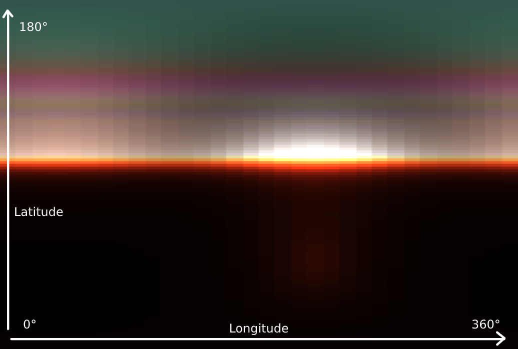
Now we'll talk about volumetric lighting . Its generation consists of four passes and begins by creating a 3D LUT texture for the sky atmosphere through raymarching through the sky itself towards the light source.

From the first time, you may not understand what exactly the texture displays in the picture, but if we rotate it 90 degrees and stretch it horizontally, everything becomes clear: we have a scattering of the atmosphere. Since it is more variable vertically than horizontally, the vertical resolution is greater. The atmosphere is represented by a sphere, so horizontal rotation is usually called longitude and vertical rotation is usually called latitude. Atmospheric scatter is calculated by the hemisphere and covers 360 degrees longitude and 180 degrees latitude for the top of the sphere. To cover different distances to the observer, the LUT texture contains 32 depth segments, and instead of recalculating the sky data in each frame, the process is spread over 32 frames.
Thanks to the LUT texture, the next pass calculates the light scattering by the observed "froxel" by analogy with a cluster obstruction on a smaller scale. You can observe several segments, from near to far, below.

In the third pass, the scattering data for each cell is multiplied into each subsequent cell in the direction of the view and written into a new 3D texture.
As a result, volumetric lighting is placed on top of the rendered image through sampling of the newly generated 3D texture based on the pixel depth.

Before

After
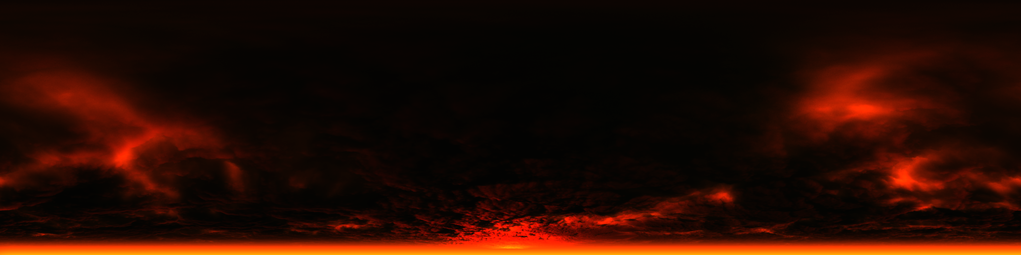
The final "visible" sky is rendered in a hemisphere if it is in the view. In this scene, the sky was not included in the review, but below you can take a look at an example of rendering the sky in an outdoor scene.
Transparency
Similar to Doom 2016, transparency is rendered by a forward pass after opaque geometry when light scattering data is present. At the same time, the scene texture loses in resolution (downsamples), and a suitable mip-level is selected to "simulate" transparency based on the smoothness of the surface. Light scattering data helps create visually good scattering from the inside of the surface.
Below you can see an example of a texture mip-chain from the scene, where more transparent surfaces fall into the viewport.
For transparency, only the pixels related to it are lost in resolution.
User interface
Typically, the last pass in a frame is the user interface. As is usually the case, the interface is rendered into a secondary full resolution LDR (eight-bit) render target, and the color is pre-multiplied by the alpha channel. During tone mapping, the interface is superimposed on the HDR texture. Getting the interface to work with the rest of the HDR content in the frame is usually tricky, but in Doom Eternal, tone mapping magically scales the interface and looks natural against other 3D content.
Post-processing
The first thing in post-processing is blur : this two-pass effect reads data from the color texture and a custom speed buffer. The first pass collects four samples on the vertical axis, the second - four along the horizontal. Then the color swatches are blended according to the pixel movement. To avoid blurring, the custom speed buffer must ensure that there are no ghosting and that the player's weapon is excluded from the process.
Next comes the targeted impact: This RG (bi-color) 1 by 1 texture contains the average illumination of the entire scene and is calculated by successively downsampling the color texture and getting the average illumination of a group of pixels. Most often, this technique is used to simulate the habituation of the human eye to a sharp change in ambient brightness. Also, the average illumination is used when calculating the impact during tone mapping.
After all this, Bloom is calculated . This effect is not enough in our example and it will not be possible to render it widely, but it is enough to know that the calculation is carried out by obtaining color data above a certain limit and successively decreasing the texture resolution to blur it.
Then tone mappingcombines all the effects. A single compute shader does the following:
- Applies distortion
- Renders over Bloom texture
- Calculates vignetting, on-camera dirt, chromatic aberration, lens flare and many other effects
- Gets exposure value based on average illumination
- Allows tonemapping to distribute HDR colors to the correct ranges for both LDR and HDR via a custom tonemapping operator.
Finally, the interface is superimposed on top.
The distortion texture is rendered even before the post-processing pass: the geometry like a haze of fire from particle effects is rendered into a new render target in a format with a quarter of the original resolution. In this render, the distortion data is stored in the red and green channels, and the occlusion in the blue. The obtained data is applied when the image is distorted at the tone mapping step.

Conclusion
Our cursory breakdown of one shot of Doom Eternal has come to an end, although I'm sure I haven't touched on a few things that affect the look of the game. In my opinion, Doom Eternal is an incredible technical success, and id Software will be able to raise the bar even further in the future. The development team has successfully demonstrated to us how smart thinking and effective planning have helped create a high-quality game, and I believe this is a great role model, as well as educational material. I look forward to future developments by id Software.
Rip and tear, until it is done.
Reference materials
- Doom 2016 Graphics Study ( translation )
- Devil is in the Details - Siggraph 2016
- Doom Eternal - Digital Foundry Tech Review
- MJP - Bindless Texturing for Deferred Rendering and Decals