We explain how to understand when your design system is out of date and what to look for when choosing a new solution. We present an overview and comparison of the top five world instruments based on the CAD comparison table on ROI4CIO.
Part I. How to know if your CAD is out of date and what to do next
Why companies are looking for other tools
When implemented, your CAD system was at the forefront of progress, and now it seems that it works like a blunt tool? A logical question arises - is it worth replacing it or is it safer to try to get more from the existing software? In favor of the change - the opportunity to choose the latest and most advanced software plays. But the downside is also strong - costs, hardware upgrades, employee training, transformation of obsolete data.
A recent Tech-Clarity study found that leading companies cut product development time by 19%, cut engineering costs by 15%, and cut lead time by 16% precisely by adopting the CAD systems they currently use. In a survey about this, it turned out that the number of companies that switched to using other CAD systems for commercial reasons increased from 31% in interviews conducted 7 years ago to 61% in 2019. At the same time, the number of companies citing the tools of the previous systems as the reason for the transition fell from 48% to 22%. That is, not only the technological side of the product has become important. Changes in the answers to these questions determine how strategic CAD tools have become for most companies.The study also showed the "dark" side of changing software - 13 weeks on average was spent restoring the performance level of the old system and 46 weeks on average - achieving full ROI on the new CAD system. Performance was restored to its previous level in 21 weeks and paid off in 50 weeks.
But why are companies changing CAD tools? Functionality and better performance remain the leading reasons. This is followed by ease of use and price. These factors are unchanged not only in the CAD market, but also in the choice of other software. In third place, the reasons for changing the supplier was the preference of users - this is associated with two trends. First, management understands that engineers need a comfortable working environment and satisfaction with the tools they use to optimize their productivity. Secondly, it speaks of the progress made by CAD vendors to facilitate the work with data, the creation of the so-called “multi-CAD” - the ability to work with several CAD solutions at once.
Despite the fact that CAD tools have changed significantly in recent years, the most common reason for moving to a new system is still a lack of necessary functionality.
Trends show that changes in a CAD vendor are more often driven by business reasons. Supplier relationships, a vendor's strategic vision, and a vendor's overall portfolio of offerings have a greater impact. This demonstrates another shift across the entire IT market - the importance of service. Companies want their CAD supplier to be a valuable partner. Over the past 5 years, companies are 82% more likely to change CAD tools simply because they don't like the supplier relationship.
When it comes to ROI, companies recognize that when they change CAD, they are investing in learning - while it is time-consuming, it translates into higher productivity in the long run.
Criteria for choosing a new CAD system

Effective 3D Modeling
A 3D model must accurately represent each component in a product and the relationship between them. It should be possible to design as few steps as possible without compromising design quality.
When evaluating CAD programs, first find out how effective each package is in creating the products your company makes. It's worth testing how easy it is to assemble a large number of parts and how purchased parts are imported from the library. As a result, the new system should provide a reduction in the number of steps by at least 20 percent.
Exchange of information within the enterprise
Most manufacturers no longer do business in just one country and rely on international communities of suppliers of parts, tools, subsystems, manufacturing equipment and design. So it is better to choose a popular CAD system that supports many formats and standards. Minimum International Standards Support — STEP, IGES, VDA, and IDF. This choice will help get rid of the endless conversion of files from one system to another, which not only takes time, but also leads to errors.
Check out the tools to fix damaged imported shapes. Do not limit expectations from data exchange and file exchange: modern systems allow employees and customers to collaborate on a project in real time. This communication saves thousands of hours and weeks of work time.
Work on a project from concept to production.
Focus on CAD programs with a rich range of applications that reduce not only design time, but also test, machining, costing and verification.
Physical testing is expensive and slow. And the current development of CAD allows you to test within the software the impact of many physical characteristics - kinematics, dynamics, stress, deflection, vibration, temperatures. Dedicated wiring design modules will help ensure the correct connection of equipment, systems with included cost estimates will allow you to monitor compliance with the estimate.
Data management
Integration of CAD with product data management systems (PDM) promises benefits and reduces headaches. Without PDM, designers can rewrite each other's work, reinvent previously developed parts. Together, these mistakes waste hundreds of hours each year and thousands of dollars on defective parts. Plus PDM-systems are not only in the storage and organization of files. They also help you find existing parts for reuse, create bill of materials for cost estimates, and feed information to manufacturing resource planning systems.
Intuitive user interface
Look for a system with a short learning curve - a clear user interface. Make sure design and manufacturing procedures flow logically from start to finish. Look for a product with computer-based tutorials and an online community to ask and get answers to.
A productive business relationship with a supplier
It has already been noted that one of the most common reasons for switching suppliers is not at all the technical aspects of the solution. Just as some airlines annoy customers with additional checked baggage fees, flight changes, paid water and blankets, some CAD vendors charge hidden fees for software and services that most customers need.
CAD: looking to the future

In order not to be mistaken with the choice of software, it is necessary not only to study its current state, but also to understand where the development of the entire sphere of computer modeling is heading. Let's see what the simulation software will improve in the coming years.
Automation and artificial intelligence. One of the biggest trends of these years is automation. This trend is due to the development of artificial intelligence. In the near future, CAD programs are expected to predict your actions or correct previous design errors. Some vendors are already embedding AI in software, and it will become even more prevalent in the coming years
. Cloud software.In the past, CAD solutions were heavyweight and ran on only one computer. With the growing use of "clouds", many applications and programs run on the cloud infrastructure. Such CAD programs are available from anywhere in the world and do not require installation, and it looks like most products will migrate that way.
The virtual reality. Visualization and rendering are constantly being improved. CAD tools still need good 3D tools to achieve optimal design previews. Thanks to virtual reality, some 3D models can be viewed in physical space thanks to helmets. True, so far it looks more promising for the architectural sphere than for mechanical engineering.
Narrow specialization or customization options.There are already many sector-specific programs already available, such as Bentley Systems' product for exclusively bridge design. This way, users have the tools and functions they need to work on a specific project. Modular systems and SaaS services will also gain momentum.
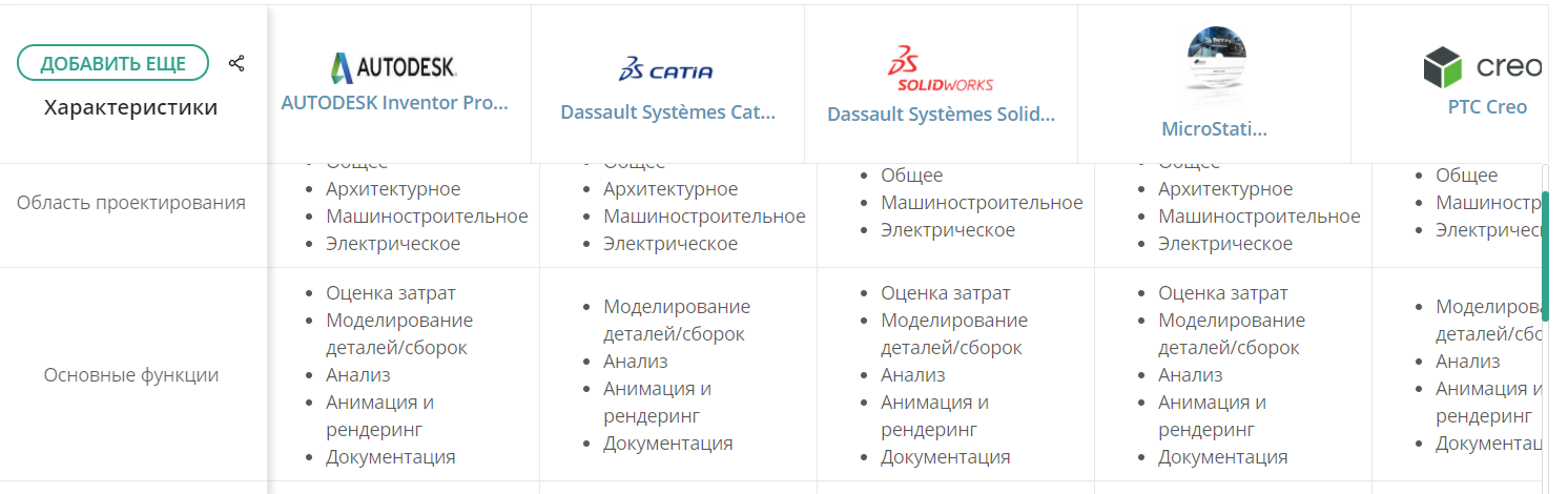
Having considered the criteria that you need to pay attention to when choosing a program, let's go directly to the software. The following is a short overview of the five leaders of the CAD market in the mechanical engineering sector, their advantages and disadvantages, we compare the main characteristics on the basis of a comparative table .
Part II. Product comparison

MicroStation by Bentley Systems
MicroStation's industry-leading engineering, modeling, visualization, and drafting capabilities enable infrastructure professionals across all industries to complete projects of any size or complexity.

Bentley MicroStation is a visual modeling software designed specifically for engineers, designers and architects. The program is equipped with tools for drawing, modeling, object management, visualization. The product is used for all types of infrastructures and utilities - buildings, roads, bridges, rails, water supply networks, mining enterprises and communication networks.
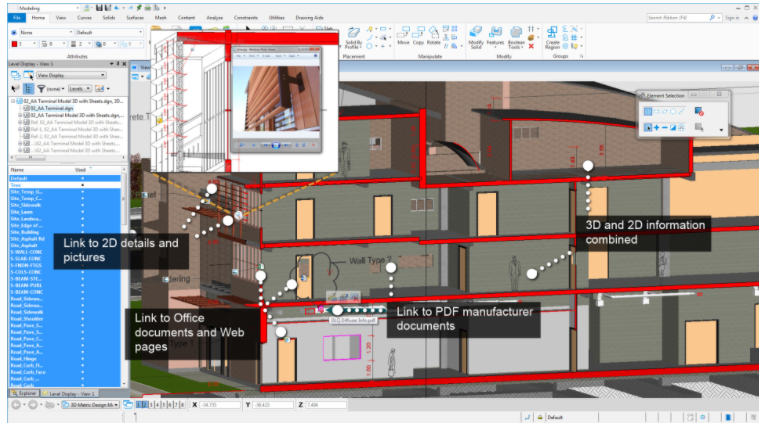
MicroStation is used by infrastructure professionals to create high quality digital projects. It is capable of supporting multidisciplinary BIM (Building Information Modeling) models, helping to create complex models used in architecture, design, construction and operation of infrastructures. You can create any geometric shape in the solution. Bentley MicroStation's 3D parametric drafting capabilities are comprehensive: all shapes can be created using solid, surface, mesh, functional and topological modeling tools.
MicroStation allows project participants to collaborate on a task. Regardless of the industries in which colleagues work, they can always familiarize themselves with drawings, models and designs. This is achieved through a powerful linking system that integrates various file formats with MicroStation. So, the solution allows you to directly edit DWG files that include 2D and 3D geometry and embedded information. Users can manipulate multiple reference files at the same time. In addition, MicroStation offers an “undo” feature that allows users to easily track and roll back any design changes, even at the component level.
The software solution promotes adherence to drawing and design standards. The product has a built-in validator that detects non-conforming items. Here you can create compliance reports to improve the quality of your models and results. And of course MicroStation supports digital signatures while protecting intellectual property rights.
MicroStation prices vary depending on the inclusion of various BIM products in the subscription. Bentley Systems uses a "trust licensing" scheme that provides pricing flexibility to users. The product earned the first place in our list for the price-to-quantity ratio of the tools provided, the wide coverage of application areas, the presence of an official supplier in the region, the support of many libraries and the possibility of teamwork on the project.
Advantages: performance, ease of use, price-quality-quantity of services and flexible payment license, 13 supported languages (including Russian), training webinars and a powerful community.
Disadvantages: works only on Windows, training materials are more in English.
Suitable for:enterprises of all sizes, urban planning, project teams responsible for creating and managing infrastructure.
Type of work process
Design area: general, architectural, mechanical engineering, electrical;
Main functions: cost estimation, part / assembly modeling, analysis, animation and rendering, documentation;
Industry: infrastructure, urban planning, structures, energy, electronics, manufacturing;
Additional features: analysis of solids and surfaces, electrical systems, piping systems, strength calculations, verification for compliance with industry standards, built-in libraries;
Recommended OS: Windows 7, 8, 10.
Inventor Professional by AutoDesk
Autodesk Inventor . C Inventor 2D- 3D- , , , .

Despite the time and effort that Autodesk has devoted over the past years to developing and promoting the Fusion 360 platform, Inventor is still a more mature and complex product. Its regular updates include not only bug fixes, but also the introduction of significant new features.
As Autodesk's flagship 3D modeling tool, Inventor provides many tools for all stages of the product development process. Building on its powerful modeling capabilities, Inventor has both built-in and advanced toolsets for modeling, rendering, CAM, and product data management.
Inventor supports three traditional 3D modeling methods: freestyle, parametric, and straight. Freestyle (“Freeform”) is used to organically shape objects such as clay. Parametric Modeling calculates various properties of the model, providing both the quantitative definitions required for the part and the configurability of the part. Direct modeling allows the designer to directly modify the faces and vertices of the model without worrying about changing other parts of the model.
The solution includes the ability to translate data from other CAD systems and drawings in industry standard DWG format. To facilitate collaboration, the solution offers a “Shared Views” feature: uploading a light version of the model to Autodesk's cloud-based model viewer. Then it can be shared with customers, suppliers, partners. They can not only view, but also measure, mark up, divide into sections and comment.
Autodesk Inventor includes a full-featured design automation tool based on simplified Visual Basic code that automates anything in a 3D model or 2D drawing, reads and writes to MS Excel and other databases, and MS Word.
With Inventor, you can optimize material selection based on environmental impact, cost and performance to make informed design decisions.
Advantages: a variety of methods for modeling three-dimensional models, ample assembly possibilities - connecting files from other CAD systems, a kinematics simulator.
Disadvantages: only for Windows, heavy load on the PC in the process of working with software, difficult to learn, with a large number of details, the program often “slows down” “crashes”.
Suitable for: design and development of machines of any kind.
Type of work process

Design area : general, architectural, mechanical engineering, electrical;
Main functions:cost estimation, part / assembly modeling, analysis, animation and rendering, documentation;
Industry: structures, consumer goods, manufacturing, medicine;
Additional features: analysis of bodies and surfaces, electrical systems, piping systems, sheet materials, generators of standard parts, strength calculation, built-in libraries;
Recommended OS: Windows 7, 8, 10.
SolidWorks by Dassault Systèmes
SolidWorks integrates powerful design tools — industry-leading parts, assemblies, and drawings — with built-in modeling, rendering, animation, product data management, and cost estimates.

SolidWorks is a CAD software that allows you to create, simulate, publish and manage 3D models.
SolidWorks has rich capabilities for simulating and testing product performance virtually under specified conditions. Analytical properties help identify and solve assembly problems early in the product development. For example, there is motion analysis, linear static analysis of parts and ensemble of parts. One of the factory testing tools is the Safety Wizard, which will help examine the job for any structural deficiencies.
SolidWorks is capable of creating large prefabricated structures containing about 100,000 parts. These complex assemblies are easy to manage with easy-to-use design creation and management tools.
Users can create various designs of sheet metal parts using specialized SolidWorks tools. Weldments tool simplifies the design and manufacture of welded structures, frames and foundations.
The solution helps you design plastic and molded structures. There are mold design capabilities, electrical cable retention and conduit design, comprehensive piping and pipe design, and documentation of wiring, piping and tubing diagrams.
One of the distinguishing features that makes this software easier to use is the ability to customize the tool palette. To make your workflow more efficient, you can place the tools you use most often where you want them to be.
SolidWorks is compatible with DWG, DXF, STEP, STL, which allows you to work with files from AutoCAD and SketchUp Pro, as well as 3D print projects. This CAD system also allows you to work with PDFs and various bitmap files, eDrawings is supported.
Advantages: one of the most popular CAD programs in the world, flexibility in customization, an easy-to-understand program is sufficient.
Disadvantages:often “crashes”, the tools for communication within the project are not developed, it consumes a lot of resources during work.
Suitable for: industrial design and modeling in medium and large enterprises, because of the price it is not profitable for small businesses.
Type of work process

Design area: general, mechanical engineering, electrical;
Main functions: cost estimation, part / assembly modeling, analysis, animation and rendering, documentation;
Industry: structures, consumer goods, energy, electronics, manufacturing, medicine, automotive;
Extra features:analysis of bodies and surfaces, electrical systems, piping systems, sheet materials, generators of standard parts, strength calculation;
Recommended OS: Windows 7, 8, 10.
Compass-3D by ASCON
A comprehensive computer-aided design system focused on mechanical engineering, drafting, cable system design and document creation for engineering projects.

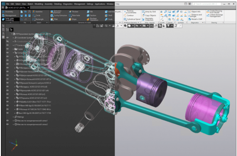
KOMPAS-3D is a powerful and comprehensive 3D mechanical design application that provides the foundation for 3D parametric solid modeling. Supports solid, surface, parametric, sheet and object modeling.
KOMPAS-3D includes support for an unlimited number of layers, smart dimensions, standard parts and centerlines, as well as a complete set of tools for creating standard drawings. The product can be expanded with additional modules.
The solution supports several design techniques: bottom-up modeling, bottom-up modeling (using off-the-shelf components), top-down modeling, top-down modeling (component design in the context of a specific project), sketch-based modeling (such as a kinematic diagram), or a combination of methods modeling.
The interface is easy to use, for training there is a built-in library "ABC KOMPAS-3D" with ready-made models and tips on the process of work. Users can work in 2D and 3D at the same time. An advantage for the CIS region is the extensive system of online help and user support groups in Russian. Also, a bonus is the paperwork in accordance with the rules of ESKD and SPDS. The program allows you to check documents for compliance with the design standards for ESKD (for example, the placement of text or the permissible distance between dimension lines), check models for manufacturability. There are about 200 types of checks that improve the quality of the developed models and documentation.
KOMPAS-3D imports a number of standard CAD file formats, including DWG, DXF, IGES, SAT, STEP and Parasolid, and even the SolidWorks eDrawings format, so the application works well in mixed design environments.
The solution comes with a number of symbol libraries, plugins, and add-ons, including electrical / heating, furniture, manufacturing, mechanical / plumbing, and automobiles. Thanks to the support for the import formats mentioned above, several third-party libraries can also be included.
The solution is not limited to object modeling - KOMPAS-3D contains tools for integration into PLM environments. True, the closest integration is still with ASCON's own engineering data management system - with LOTSMAN: PLM.
Benefits: easy to learn, interface and additional information in Russian, support for many formats, a wide range of tools.
Disadvantages: the likelihood of problems when importing 3D models from third-party programs, it is more difficult to design in 3D than in 2D, visualization is lame.
Suitable for: beginners, infrastructure and industrial design, blueprints.
Type of work process
Design area: general;
Main functions: modeling of parts / assemblies, documentation;
Industry: structures, consumer goods, manufacturing;
Extra features:analysis of bodies and surfaces, electrical systems, piping systems, sheet materials, generators of standard parts, strength calculation, modules for an additional fee;
Recommended OS: Windows 7, 8, 10.
Creo by PTC
This 3D CAD solution provides designers with innovative tools for the entire product development cycle - from initial concept to design, modeling and analysis.

PTC Creo provides design professionals with a robust and scalable toolbox with advanced productivity tools. For example, starting with Series 4 of Creo Solution Packs, there is an optimized Augmented Reality feature, Creo AR Design Share. This makes it much easier to collaborate online with stakeholders anywhere in the world.
With Creo Unite technology, you can open, import, and save data created outside of PTC Creo, work with assemblies from systems such as Autodesk Inventor, CATIA, Siemens NX, Solid Edge, and SolidWorks.
The product supports conceptual design, industrial design, routable system design, 3D design, simulation.
Creo Simulate is a feature that helps you recognize and fix design errors before prototyping. Like most CAD programs, Creo also uses a layer manager, allowing you to select, organize, and edit different sections without manipulating the entire structure.
The 3D rendering capabilities look very realistic, and there is a lot of useful information in the PTC knowledge base and user-created tutorials. The new release includes a built-in add-on module, Creo Generative Topology Optimization, which automatically generates optimized product designs based on constraints and requirements — including materials and manufacturing processes.
Creo can extract 3D models from 2D images as well as create 2D images from 3D models. The solution works with DWG, DXF, STEP, STL, PDF and graphic files, plus the ability to 3D print projects. PTC also offers Creo View Mobile, an application that allows you to view and demonstrate designs on a smartphone or tablet.
Benefits: powerful rendering tool, many features, cutting edge technology.
Disadvantages: Long learning curve, high cost, predominantly English speaking community.
Suitable for: advanced users, industrial design and modeling, aerospace solutions.
Type of work process

Design area: general, mechanical engineering, electrical;
Main functions: modeling of parts / assemblies, analysis, animation and rendering, documentation;
Industry: consumer goods, electronics, manufacturing, medicine, automotive, aircraft construction;
Additional features: analysis of bodies and surfaces, sheet materials, generators of standard parts;
Recommended OS: Windows 7, 8, 10.
Author: Natalka Chekh, for ROI4CIO