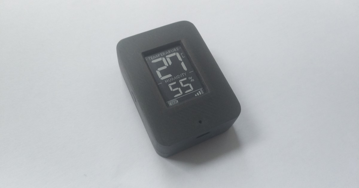
The goal of this project was to develop a miniature sensor, comparable in size to conventional wireless temperature sensors, but at the same time getting data output on the device itself. And under all these conditions, the device would work on a small battery for a long time. What came of this, please evaluate and do not skimp on comments.
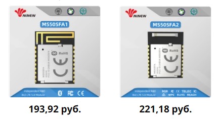
The sensor works on nRF52 chips, for this project a module from MINEW was chosen. The module is small, has 18 pins, 13 of which are gpio, two antenna options, printed and ceramic, as well as several options for chips, nRF52810 and nRF52832, are installed on the module, and after a short conversation with the company's management, they put nRF52811 chips on these modules without any questions ... So, by the way, I got my first 811s and, moreover, at a price one and a half times lower than I could buy just chips from suppliers in Russia, but that's another story. The module has a DC-DC version and a watch quartz. Module dimensions 12mm x 15mm. There is a metal screen.
From the line of e-ink displays, the choice naturally fell on a fairly new model with a screen size of 1.02 inches. The cost of one inch of e-ink was 500 rubles, which seemed acceptable to me. Small difficulties with the development of the board for this display were caused by its connector, a 30-pin FPC with a pitch of 0.5mm. The width of the FPC connector is much larger than the width of the display itself, which caused a design inconvenience. But it was easier with the display strapping, it is easier than on other models ( datasheet GDEW0102T4 ).

From a variety of digital temperature and humidity sensors, I decided to stay on the sht20 sensor, I had enough of them, simple enough, good price, convenient size. Also, one of the advantages can be called the fact that instead of sht20, if desired, it is easy to install sht21, si7020, si7021, htu20d, htu21d and hdc1080, but the latter option is not very good;).
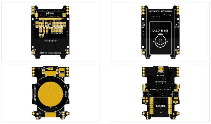
Two boards were designed for the sensor, one for the screen and its strapping, the second for a radio module, a temperature and humidity sensor and a battery. The key parameters for board sizes were screen and battery sizes. On the board with the screen, there were holes for screws (1.4 x 3) for fixing the board to the case, on the second board, cutouts were made for easy screw installation. Since this is a DIY device, I could afford to put a "tasty" CR2450 battery. Well, if one day it seems to me that the device is thick, then I can always solder the holder for a CR2430 battery. As a result, we got two boards measuring 36mm by 26mm.
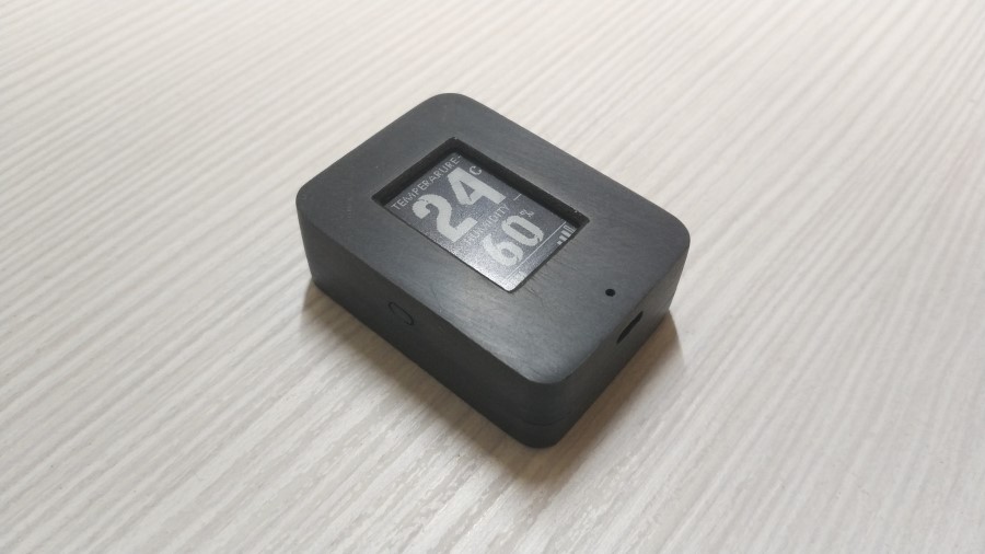
The case was designed in SolidWorks, the models of the boards were exported from DipTrace in DXF format, which were already converted into 3D models in SolidWorks. The case consists of two parts and a button. The halves of the case are fastened to each other in the same way with screws (1.4 x 4) on one side and a protruding "hook" on the other side. There are two holes for air circulation for the temperature and humidity sensor.

In this project, the body was printed on an FDM printer, of course, the print quality is lower than on an SLA printer, but in terms of strength, products made from liquid resins are much inferior to products made from filaments, and due to the peculiarities of the body, strength was important. So I was mentally prepared for grinding and polishing. In principle, it turned out quite well.

This is approximately how the hardware development took place, I tried to describe all the stages and some of the nuances, if it seemed to you time-consuming, then it was not, the software was actually labor-intensive. As before, I do my projects under MySensors, although I confess that I am no longer with the same enthusiasm as before. At some moments I began to restrain myself, some things are missing, some are simply impossible. At the moment, I see Open Thread as an alternative for myself, at least it seems quite attractive.
Device diagram


As a result, we managed to implement all our requirements for functionality. The device can work with the UD controller, as well as the device can work directly with any device in the MySensor network. Binding of devices for direct exchange can occur both through the configuration of devices through the UD controller, using external commands, or without the participation of the UD controller by simply pressing a button to activate the binding mode. The temperature sensor and another device to which the sensor is bound can normally support exchange even without a working MySensors gateway or a working UD controller, which certainly increases fault tolerance. A separate issue was with the display eink drivers, probably because the display is quite new,on the manufacturer's website and the WaveShare website (which offers eink Good Display screens under its own brand), the library implementations are quite raw. I had to redo something, add something.
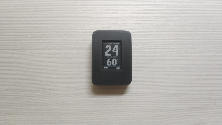
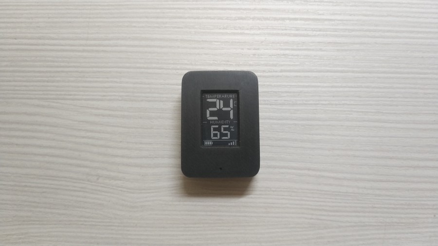
The sensor has support for several languages, color inversion by an external command in the device configuration mode, several font options also changeable by an external command in the device configuration mode. The sensor displays temperature and humidity readings, battery power and signal strength. The interval for measuring temperature and humidity, the interval for measuring the battery level can also be set by an external command. For temperature and humidity in minutes, for battery level in hours. The sensor transmits the following data to the UD: temperature, humidity, charge level in%, voltage, signal level, reason for reboot.

You can see how it looks in a small video:
Timestamps of interesting points:
3.10 - Configuring (font change, color inversion)
5.10 - Consumption metering, WTD work
If someone is interested in my developments, then after reading the article I recommend going to the channel and subscribing, there I publish information on new developments first of all ...
In sleep mode, the sensor consumes 2μA, WTD reset every 5 seconds, consumption at the time of reset is 4-5μA. In the mode of operation with a screen and a temperature and humidity sensor of 2-3mA, in a transmission mode of 5-8mA, such a range of 3 mA is due to the fact that the sensor itself regulates the transmission power based on the signal level data.
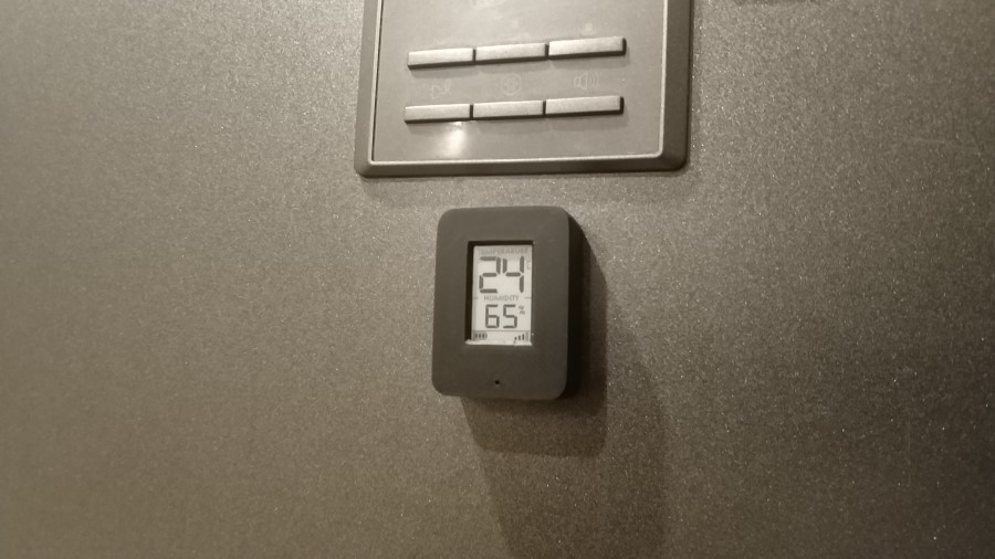
Under the spoiler photos of the sensor


On this I want to bow out, if you are interested in everything related to DIY, you are a DIY developer or just want to start, you are interested in using DIY devices, I invite everyone interested in telegram chat - DIYDEV
Anyone who wants to make devices, start building automation of their home, I propose to get acquainted with easy-to-learn Mysensors protocol - telegram chat MySensors
And for those who are looking for mature enough solutions for home automation, I invite you to the Open Thread telegram chat .
My GitHub of this project , diagram, gerber files, 3D models of the case, bom, software .
Everyone is kind as always!