1. What kind of applications
Let's first take a look at what apps are offered. We enter the site https://all-hw.com/ .
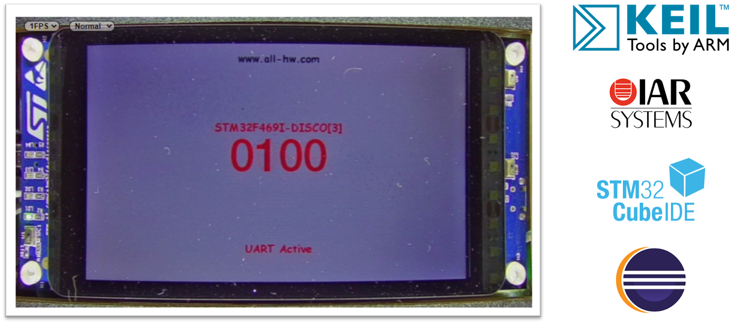
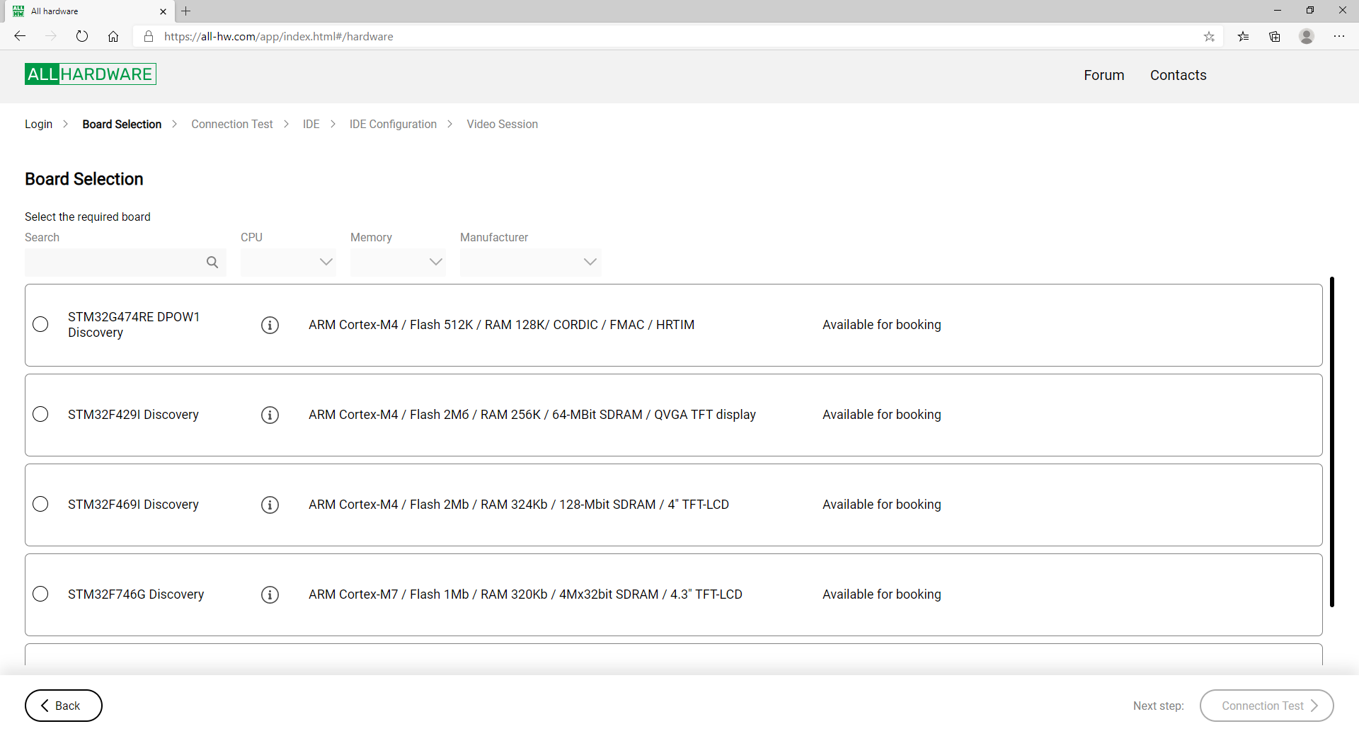
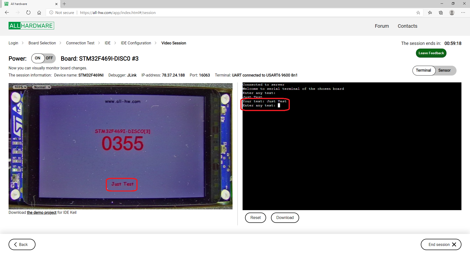
You need to log in there (registration is free). After that, a list of available boards will be displayed. The first of them does not have a screen, so it is inconvenient as an illustration for the article. The second is banal, everyone has it, it's just not interesting to talk about it. I will choose the third - STM32F469I Discovery . After going through a few steps, I find myself on the following page: Actually, on the left we see the board that the camera removes. And that very application works there. The counter just ticks. And if you enter a line in the terminal on the right, it will be displayed on the screen, since the terminal is connected to the UART debug port. Well, here I entered Just Test.

It seems that an application for a controller to implement this functionality is not complicated, but ... But ... But I repeat, we take the number of types of ST boards and multiply by at least three. And again, a very important condition: the development time of this application should not be long. We need to develop it as quickly as possible. And it must be compiled by at least three compilers.
2. Possible ways
The first thing that comes to mind is to develop a typical application in the STM32Cube MX. There, you can generate everything for three development environments, and quickly add standard devices. That's how it is, but:
- If you look at the examples of working with applications created through CubeMX, you can see that there, after automatic creation, you still need to modify a lot with a file. That is, although time is saved, it is still not maximum.
- , .
- Cube MX STemWin, ( , , , ST STemWin TouchGFX, – ).
Actually, this is enough to postpone such an option in reserve and see if there are simpler solutions ... It turns out that there are, and they are also related to the Cube MX. Anyone who has worked with this environment knows that it consists of core code and packages that serve a specific family of controllers. What is the package? This is a ZIP file. Let's download and unpack it. Take, say, a package for a brand new STM32H747. I have this file en.stm32cubeh7_v1-8-0.zip.
And we see such richness in it:

These are typical solutions for different prototyping boards with this type of controller. Okay. We enter our catalog STM32H747I-DISCO... There are separately ready-made applications and separately - examples for working with controller blocks. For those who just want to build an example, there is nothing interesting here, but developers of a typical demo application should study the contents of the UART directory.

And from applications, well, of course, STemWin. And the simplest. Hello World. The directory in which it is located will be of interest to all users.

We will make our example based on this application. Why? We enter the STemWin_HelloWorld directory and see:

ST programmers did everything for us. They created sources that can be compiled from Keil, from IAR and from Eclipse (which is, in fact, Cube-IDE). Thus, it is enough to correct these sources, and the task will be solved without editing the files that depend on the development environments! Well, and the Hello World project, it also displays texts on the screen. It is enough to add UART support to it, and everything will work. That is why I noted above that the UART example is also useful for developers.
And in this particular case, I step on the throat of my own song. If anyone has read my previous articles, they know that I hate HAL. HAL and optimization are two incompatible things. In real projects, I use either direct work with hardware or Konstantin Chizhov's drivers (mcucpp library). But in this particular case, this is not at all the case. We just make a program that displays texts and works with a COM port. On a controller with a clock frequency of hundreds of megahertz. To be honest, at the time of Ona, an ordinary BK-shka coped with this, the processor of which worked at a frequency of 3 MHz. Moreover, the BK-shki did not have RISC commands, there was not even a pipeline. But there was a multiplexed bus (that is, several clocks per cycle) and an asynchronous DRAM without caching. In short,the performance was only 300 thousand register-register operations per second. And this was enough to solve the problem of outputting texts and working with UART (through the IRPS block). That is, the optimality of the HAL code for this task on modern STM32s is also quite enough for the tasks at hand. But the development speed when using HAL will be the highest.
A new board will appear, it will definitely have HAL with unified calls attached to it. We will correct the initialization in the typical example, according to the attached UART example, and the work, it will always be the same. Development speed is tens of minutes. Not even a watch. That is, to solve this problem, it is definitely best to use HAL, although I do not like it for combat cases.
All. The minimum of theory, without which it is impossible to move on to practice, I told. I will tell you more detailed theoretical things after the laboratory work. So let's move on to experiments.
3. What the end user should do
3.1 Download the package
So. You are not going to immediately create something of your own, but first you want to play with a ready-made example taken from the All-Hardware website. What do you need to build and run it? First, you need to download libraries for a specific board. Working with Open Source solutions, I have already come across the fact that it is not enough to download a project. We still need to install 100,500 instruments and download 100,500 third-party libraries. Here you only need to download and unpack one file. True, his size is gigantic. But the content is just great. So. We need packages for STM32 CubeMX. Now a direct link to their repository looks like this:
www.st.com/en/development-tools/stm32cubemx.html#tools-software
Which package should be downloaded is shown in the table below.
| Pay | Package |
|---|---|
| STM32F429I Discovery | STM32CubeF4 |
| STM32F469I Discovery | STM32CubeF4 |
| STM32G474RE DPOW1 Discovery (no screen) | STM32CubeG4 |
| STM32F746G Discovery | STM32CubeF7 |
| STM32H747I Discovery | STM32CubeH7 |
3.2 Copying the project and getting to work
The structure of the packages is the same inside, so then we go to the directory with the following hierarchy:
<Package name> \ Projects \ <Board name> \ Applications \ STemWin.
Copy the directory with the example there. We get something like this:

The position of the directory is important, since the paths to the libraries are written in a relative format. If the project is not building due to the huge number of missing files, you are not guessing with its location in the directory hierarchy.We enter the catalog, select a project variant for one of the development environments, open the project, work with it ... End of instructions!

3.3 Feature of STM32G474RE DPOW1 Discovery board
This board does not have a screen, which means that there is no STemWin catalog in the proprietary package for it. Therefore, the project should be placed on the next level:
\ STM32Cube_FW_G4_V1.3.0 \ Projects \ B-G474E-DPOW1 \ Examples \ UART
4. How projects are created
How easy it is to assemble an example is clear. Now let's look at how these examples are done. Perhaps this information is useful for those who want to do something other than just displaying texts on the screen. Well, when in a few months it will be necessary to implement the next board, and I have already forgotten everything, I will open this article myself to refresh the instructions in my memory.
4.1 Adding and Initializing UART
The typical STemWin Hello World example predictably lacks a UART. It must be added. It would seem that we take the sample code and add it. Alas, life is more complicated. In a work function, we do it this way. But there are some nuances during initialization. To begin with, different prototyping boards have different ports connected to the USB-UART adapter built into the JTAG adapter. Which one is connected, you need to look in the description for the board. Usually, of course, USART1, but it's better to double-check.
Further, the diversity is introduced by the fact that as controllers develop, various useful functions are added to the UART equipment. They also need to be initialized in the HAL of the new boards. In particular, working with FIFO.
Therefore, I suggest the following typical steps:
- Add a port handle.
- Add UART hardware initialization.
- Add initialization of UART pins.
- Add UART interrupt handler.
With the handle, everything is clear and universal. It will look something like this:
UART_HandleTypeDef huart1;See the rest in the example of their directory \ <Package Name> \ Projects \ <Board Name> \ Examples \ UART .
For example, project \ STM32Cube_FW_H7_V1.8.0 \ Projects \ STM32H747I-DISCO \ Examples \ UART \ UART_WakeUpFromStopUsingFIFO .
In the main () function there is an initialization of the UART itself (you just need to make sure that the speed is 9600, if not, enter it). The connection with the legs is configured in another file, in the
void HAL_UART_MspInit (UART_HandleTypeDef * huart) function .
I prefer to put it all in one function. Since time is limited, I did not look at compiling such a function from these materials, placing it in the main.c file and not forgetting to call it from the main () function.
static void MX_USART1_UART_Init(void)
{

  /* USER CODE BEGIN USART1_Init 0 */
	  GPIO_InitTypeDef  GPIO_InitStruct;


  /* USER CODE END USART1_Init 0 */

  /* USER CODE BEGIN USART1_Init 1 */

//	__HAL_RCC_LPUART1_CLK_ENABLE();
	__HAL_RCC_USART1_CLK_ENABLE();

  /* USER CODE END USART1_Init 1 */
  huart1.Instance = USART1;
  huart1.Init.BaudRate = 115200;
  huart1.Init.WordLength = UART_WORDLENGTH_8B;
  huart1.Init.StopBits = UART_STOPBITS_1;
  huart1.Init.Parity = UART_PARITY_NONE;
  huart1.Init.Mode = UART_MODE_TX_RX;
  huart1.Init.HwFlowCtl = UART_HWCONTROL_NONE;
  huart1.Init.OverSampling = UART_OVERSAMPLING_16;
  huart1.Init.OneBitSampling = UART_ONE_BIT_SAMPLE_DISABLE;
  huart1.Init.ClockPrescaler = UART_PRESCALER_DIV1;
  huart1.AdvancedInit.AdvFeatureInit = UART_ADVFEATURE_NO_INIT;
  if (HAL_UART_Init(&huart1) != HAL_OK)
  {
    Error_Handler();
  }
  if (HAL_UARTEx_SetTxFifoThreshold(&huart1, UART_TXFIFO_THRESHOLD_1_8) != HAL_OK)
  {
    Error_Handler();
  }
  if (HAL_UARTEx_SetRxFifoThreshold(&huart1, UART_RXFIFO_THRESHOLD_1_8) != HAL_OK)
  {
    Error_Handler();
  }
  if (HAL_UARTEx_EnableFifoMode(&huart1) != HAL_OK)
  {
    Error_Handler();
  }

  /* Enable the UART RX FIFO threshold interrupt */
  __HAL_UART_ENABLE_IT(&huart1, UART_IT_RXFT);

  /* Enable the UART wakeup from stop mode interrupt */
  __HAL_UART_ENABLE_IT(&huart1, UART_IT_WUF);

  /* USER CODE BEGIN USART3_Init 2 */
	__HAL_RCC_GPIOA_CLK_ENABLE();

  /*##-2- Configure peripheral GPIO ##########################################*/
  /* UART TX GPIO pin configuration  */
  GPIO_InitStruct.Pin       = GPIO_PIN_9;
  GPIO_InitStruct.Mode      = GPIO_MODE_AF_PP;
  GPIO_InitStruct.Pull      = GPIO_PULLUP;
  GPIO_InitStruct.Speed     = GPIO_SPEED_FREQ_VERY_HIGH;
  GPIO_InitStruct.Alternate = GPIO_AF7_USART1;

  HAL_GPIO_Init(GPIOA, &GPIO_InitStruct);

  /* UART RX GPIO pin configuration  */
  GPIO_InitStruct.Pin = GPIO_PIN_10;
  GPIO_InitStruct.Alternate = GPIO_AF7_USART1;

  HAL_GPIO_Init(GPIOA, &GPIO_InitStruct);

  /* NVIC for USART */
  HAL_NVIC_SetPriority(USART1_IRQn, 0, 1);
  HAL_NVIC_EnableIRQ(USART1_IRQn);


  /* USER CODE END USART1_Init 2 */

}
, , JTAG. . — , JTAG , . .Well, interrupts are simple. We are looking for a file with the _it.c suffix in the example and transfer the UART lines to the file with the _it suffix of our project.
In this case, from the file
\ STM32Cube_FW_H7_V1.8.0 \ Projects \ STM32H747I-DISCO \ Examples \ UART \ UART_WakeUpFromStopUsingFIFO \ CM7 \ Src \ stm32h7xx_it.c
to the file
\ STM32Cube_FW_H7_V1.8.0 \ STM32Cube_FW_H7_V1.8.0 \ STM32Cube_FW_H7_V1. \ STemWin \ Demo_H747 \ CM7 \ Core \ Src \ stm32h7xx_it.c
transfer the fragment:
extern UART_HandleTypeDef huart1;
…
void USART1_IRQHandler(void)
{
 HAL_UART_IRQHandler(&huart1);
}
All.
4.2 Editing the main work function
With the main working function, in principle, everything is simpler. Although, not in principle, and in particular - not entirely, but we will talk about this below. For now, let's just see which function is called at the end of the main function. In this case, these are:
MainTask();
This means that the main work is done in it. We just replace its body with a typical example taken from our site.
4.3 What's next?
Further - you can carry examples of other equipment, as we just did with the UART equipment. True, the control of the operation of this equipment is beyond the scope of this article. As you can see, the typical control on the WEB page is only for the image and for one UART. The rest is forwarded a little more difficult. Nevertheless, I cannot help but tell you how I was once instructed to make a Morse code generator based on the STM32G474RE DPOW1 Discovery board in one evening . One evening to develop from scratch on an unfamiliar board does not dispose you to read hundreds of pages of documentation. If the project was done for centuries, I would simply begin to prove to the management that it is not right and that everything should be carefully studied. But the project was also with a short life cycle. So I decided to follow the path of pulling out examples.
So, for Morse code you need a sine with a frequency of 1 KHz ... With the usual movement of your hand, unpack the file en.stm32cubeg4_v1-3-0.zip and examine the directory D: \ tmp \ STM32Cube_FW_G4_V1.3.0 \ Projects \ B-G474E-DPOW1 \ Examples ... And nothing good there not found ...

There is nothing useful in the DAC directory.

Is that the end? Not really. Let's look at examples from other boards with the same crystal (albeit in different packages) ... And this is the beauty we find for the Nucleo board!

The beauty is that inside the main.c file there is a table for generating the sine:
/* Sine wave values for a complete symbol */
uint16_t sinewave[60] = {
0x07ff,0x08cb,0x0994,0x0a5a,0x0b18,0x0bce,0x0c79,0x0d18,0x0da8,0x0e29,0x0e98,0x0ef4,0x0f3e,0x0f72,0x0f92,0x0f9d,
0x0f92,0x0f72,0x0f3e,0x0ef4,0x0e98,0x0e29,0x0da8,0x0d18,0x0c79,0x0bce,0x0b18,0x0a5a,0x0994,0x08cb,0x07ff,0x0733,
0x066a,0x05a4,0x04e6,0x0430,0x0385,0x02e6,0x0256,0x01d5,0x0166,0x010a,0x00c0,0x008c,0x006c,0x0061,0x006c,0x008c,
0x00c0,0x010a,0x0166,0x01d5,0x0256,0x02e6,0x0385,0x0430,0x04e6,0x05a4,0x066a,0x0733};
We check and make sure that yes. This example generates a sine or triangle at the DAC output. And just with a frequency of 1 KHz. So that's great! Since time was limited, I didn't even bother to read any theory. I just made sure that all the formation takes place at the hardware level by taking a quick look at the code. After that, in the project, I replaced the controller with the one in the required board, assembled, filled in, started it and, after running the oscilloscope probe along the legs, found the one on which that sine is present. Then I connected it to the input of the speakers, replaced the generation of a sine or a triangle with the generation of a sine or silence (yes, I made another table from only zeros) ... Well, writing an applied part with Morse code was as easy as shelling pears. I remembered my youth, the military department, Colonel Pavlov ...
In general, the "find an example, insert it into your code" technique is quite effective. And the approach “to build a typical example - download a huge library” contributes to this, because all these branded examples are part of it.
5. Problems in unification
A colleague of mine likes to quote the following philosophical statement:
“In theory, there is no difference between theory and practice. In practice, it is. "
When working with a bunch of different STM32s, I regularly remembered it. I have already said about inevitably different UARTs, but it would seem that the unified StemWin should not present any surprises ... Presented!
5.1 STM32H747
The Hello World caption is drawn. But when I transfer the working code, I see a blue screen. It's just that we first draw a red screen for a second, then a green screen for a second, then a blue screen for a second, then work begins. If you put a breakpoint immediately after initialization, even before any drawing, when it is triggered, the timer readings from the last start are visible on the screen. Then they are overwritten by the same blue screen. What?
I remove the output of three colors by a second, and immediately add the work. It works, but it quickly freezes forever. Gradually I figure out what freezes after 37 milliseconds. What kind of magic time is this? One millisecond is clear. System tick. But 37. Yes, at least something round, close ...
How long, short, but I find out that everything is displayed in the interrupt handlerHAL_DSI_IRQHandler (DSI_HandleTypeDef * hdsi) . It is called, everything is displayed, after which its calls are terminated. Everything is formed in the buffer, but does not appear on the screen. More precisely, everything hits the screen twice in the life of the program. At initialization (the same artifact from a past life) and after 37 ms. Everything that was between, no one will see.
On the mind - you need to study the documentation and figure out what's what. But in fact - the time for the task is not a little, but very little. It is clear that the interruption must be provoked, but how? I'm honestly trying to call GUI_Exec (), although GUI_Delay () is called there anyway ... Doesn't help.
The example is dead. Rather, it's funny there. Hello World is output as it does in the first 37ms. And then - a dead example. Ok, I'll take an example with animation from the same catalog. He works. Gradually I figure out what needs to be dragged out of it for our example to work ... This is how our typical code looks like:
  	GUI_SetBkColor(GUI_RED);
        GUI_Clear();
  	GUI_Delay(1000);
  	GUI_SetBkColor(GUI_GREEN);
  	GUI_Clear();
  	GUI_Delay(1000);
  	GUI_SetBkColor(GUI_BLUE);
  	GUI_Clear();
  	GUI_Delay(1000);
Well, it's logical! And it works! .. On other boards ... But after such an edit, it somehow moved on the H747:

The same text.
	GUI_MULTIBUF_Begin();
  	GUI_SetBkColor(GUI_RED);
        GUI_Clear();
	GUI_MULTIBUF_End();
  	GUI_Delay(1000);
	GUI_MULTIBUF_Begin();
  	GUI_SetBkColor(GUI_GREEN);
  	GUI_Clear();
	GUI_MULTIBUF_End();
  	GUI_Delay(1000);
	GUI_MULTIBUF_Begin();
  	GUI_SetBkColor(GUI_BLUE);
  	GUI_Clear();
	GUI_MULTIBUF_End();
  	GUI_Delay(1000);
But in general, it works, and in particular - the red and green screens last for a second, and the blue one flickers and the working screen appears immediately. After a small number of experiments, it turned out that everything starts to work fully in this form:
	GUI_MULTIBUF_Begin();
  	GUI_SetBkColor(GUI_RED);
        GUI_Clear();
	GUI_MULTIBUF_End();
	GUI_MULTIBUF_Begin();
	GUI_MULTIBUF_End();
	GUI_MULTIBUF_Begin();
	GUI_MULTIBUF_End();
  	GUI_Delay(1000);
	GUI_MULTIBUF_Begin();
  	GUI_SetBkColor(GUI_GREEN);
  	GUI_Clear();
	GUI_MULTIBUF_End();
	GUI_MULTIBUF_Begin();
	GUI_MULTIBUF_End();
	GUI_MULTIBUF_Begin();
	GUI_MULTIBUF_End();
  	GUI_Delay(1000);
	GUI_MULTIBUF_Begin();
  	GUI_SetBkColor(GUI_BLUE);
  	GUI_Clear();
	GUI_MULTIBUF_End();
	GUI_MULTIBUF_Begin();
	GUI_MULTIBUF_End();
	GUI_MULTIBUF_Begin();
	GUI_MULTIBUF_End();
  	GUI_Delay(1000);
So much for unification ... There was a suspicion that the setting was to blame:
/* Define the number of buffers to use (minimum 1) */
#define NUM_BUFFERS  3
But experiments with correcting it did not give an ideal result, and time did not allow to study the details. Maybe someone in the comments will tell you how to act correctly, and this section shows how you can act in a limited time for development. In the meantime, the code has remained in such a terrible state. Fortunately, this is not a tutorial, but just an example of working code.
5.2 STM32F429
This board is old, what could be wrong with it? Rudiments! At the old board, outgrowths that exist, but have long ceased to work, come out. Run the Hello World example and see:

The image is rotated 90 degrees relative to the typical one. What could be easier? Back in 2016, while dragging the firmware of the MZ3D 3D printer from Arduinka to STM32F429, I personally turned the picture with simple settings. Come on. How are things going here? And here are the settings!
#define LCD_SWAP_XY  1
#define LCD_MIRROR_Y 1
Trying to change them, it doesn't help. Checking where they are used ... But nowhere! They are just announced. I suspect that they stopped processing when DMA2D was implemented, but I will not vouch. However, there is the same function. Here's advice from dozens of forums. I used this function in 2016:
GUI_SetOrientation(GUI_SWAP_XY)
Some still add a mirroring constant ... But not the point. This function does not work in 2020! Doesn't work and that's it! And the library is delivered in object form, why it does not work - no one will tell.
Well, I still understand screens. I go to the file \ STM32F429-DISC1 \ Drivers \ BSP \ Components \ ili9341 \ ili9341.c (yes, it is write-protected, but it's easy to remove). The graphics chip is configured there. We change.

The same text.
  ili9341_WriteReg(LCD_MAC);
  ili9341_WriteData(0xC8);
on

The same text.
  ili9341_WriteReg(LCD_MAC);
  ili9341_WriteData(0x48|0x20);
The image, of course, rotates ... But the buffer is clearly configured somewhat incorrectly:

These are the dimensions:
#define XSIZE_PHYS 240
#define YSIZE_PHYS 320
also do not affect the work in any way. The same applies to this site:
#define  ILI9341_LCD_PIXEL_WIDTH    ((uint16_t)240)
#define  ILI9341_LCD_PIXEL_HEIGHT   ((uint16_t)320)
But the site is more interesting:
  if (LCD_GetSwapXYEx(0)) {
    LCD_SetSizeEx (0, YSIZE_PHYS, XSIZE_PHYS);
    LCD_SetVSizeEx(0, YSIZE_PHYS * NUM_VSCREENS, XSIZE_PHYS);
  } else {
    LCD_SetSizeEx (0, XSIZE_PHYS, YSIZE_PHYS);
    LCD_SetVSizeEx(0, XSIZE_PHYS, YSIZE_PHYS * NUM_VSCREENS);
  }
I added negation for fun:

The same text.
  if (!LCD_GetSwapXYEx(0)) {
    LCD_SetSizeEx (0, YSIZE_PHYS, XSIZE_PHYS);
    LCD_SetVSizeEx(0, YSIZE_PHYS * NUM_VSCREENS, XSIZE_PHYS);
  } else {
    LCD_SetSizeEx (0, XSIZE_PHYS, YSIZE_PHYS);
    LCD_SetVSizeEx(0, XSIZE_PHYS, YSIZE_PHYS * NUM_VSCREENS);
  }
I got this beauty.

I got a similar, but not exactly the same beauty in other experiments, I don’t remember any more ... In short, we all come to the same disappointing conclusion. We have to sit down and sort it out ... But there is no time allocated for the trial. What to do? Fortunately, I managed to get the answer to this question from Google. As a result, the typical code in the demo application looks like this:
GUI_DispStringHCenterAt("www.all-hw.com", xSize / 2, 20);
And for F429 it must be reduced to this form:
  GUI_RECT Rect = {20-10, 0, 20+10, xSize};
  GUI_DispStringInRectEx("www.all-hw.com", &Rect,
      GUI_TA_HCENTER | GUI_TA_VCENTER,
      20, GUI_ROTATE_CCW);
The function of outputting rotated text is used. However, for this you have to add the "rectangle" entity. Well, what can you do. And the counter has to be displayed not by the function of printing a number, but first by forming a string, and only then by displaying it in a rotated form. But otherwise, everything turned out almost universally. It is even possible, on the contrary, to display texts everywhere in this way, but not to indicate the rotation flag everywhere. But it seems to me that this will already be a perversion.
6. Conclusion
We examined the methodology for developing typical programs for various STM32 boards, both from the point of view of the developer and from the point of view of the user who simply downloaded a demo application for his board and just wants to build it without thinking about physics. We also looked at examples showing that, unfortunately, the degree of code unification is high, but does not reach one hundred percent. The knowledge gained can be checked by working alternately with different boards through the All-Hardware service, without spending money on their purchase.
The article shows how to sort things out rather superficially. This allows you to quickly master a specific board. But, of course, the longer you deal with her, the more profound knowledge you will get. When solving real problems, this is extremely important, since complex programs, in which the author does not understand the physics of processes, are a path to errors in algorithms. I wish everyone to master everything deeply enough. Yes, using the hardware from the All Hardware service.