The report can be divided into three parts:
- how the 6502 processor works and how to emulate it using JavaScript,
- how the graphics output device works and how games store their resources,
- how sound is synthesized using web audio and how it is parallelized into two streams using an audio orlet.
I tried to give tips on optimization. Still, emulation is the thing, at 60 FPS there is little time left for code execution.
- Hello everyone, my name is Zhenya. Now there will be a little unusual talk, Saturday, about the project for many Saturdays. Let's talk about emulation of computer systems, which can be implemented on top of existing web technologies. In fact, the web is already pretty rich in tools, and you can do absolutely amazing things. More specifically, we will talk about the emulator to all, probably, the famous Dandy console from the 90s, which is actually called the Nintendo Entertainment System.

Let's remember a little history. It started in 1983 when the Famicom came out in Japan. It was released by Nintendo. In 1985, an American version was released, called the Nintendo Entertainment System. In the 90s we had the same Taiwanese region called Dandy, but secretly, this is an unofficial prefix. And the last such iron gift from Nintendo was in 2016, when the NES mini came out. Unfortunately, I don't have an NES mini. There is SNES mini, Super Nintendo. Look at what a small thing, and right on this slide you can see Moore's Law in all its glory.
If we look at 1985 and the ratio of the console to the joystick, and in 2016, we can see how much smaller everything has become, because people's hands do not change, the joystick cannot be made smaller, but the console itself has become tiny.
As we have already noticed, there are many emulators. We didn’t say it, but at least one official noticed. This thing - SNES mini or NES mini - is not really a real set-top box. This is a piece of hardware that emulates the console. That is, in fact, this is an official emulator, but which comes in such a funny iron form.
But as we know, since the 2000s, there are programs that emulate the NES, thanks to which we can still enjoy games from that era. And there are many emulators. Why another one, especially in JavaScript, you ask me? When I did this thing, I found three answers to this question for myself.
- , . - , . . , - , - . . . , , . , -.
- , , . , , , , NES — , , NTSC, 60 . 16 , . .
- . , . , , . , , — , . . , , .
I also watched the presentation by Matt Godbold, who also talked about emulating the processor that runs the NES. He said it's funny that we are emulating such a low-level thing in such a high-level language. We don't have access to hardware, we work indirectly.

Let's move on to the consideration of what we will emulate, how we will emulate, etc. We will start with the processor. The NES itself is iconic. For Russia, it is understandable, this is a cultural phenomenon. But in the West, and in the East, in Japan, it was also a cultural phenomenon, because the console, in fact, saved the entire home video game industry.
The processor is also installed in the iconic MOS6502. What is its significance? At the time it appeared, its competitors were priced at $ 180 and the MOS6502 was priced at $ 25. That is, this processor launched the personal computer revolution. And here I have two computers. The first is Apple II, we all know and imagine how significant this event was for the world of personal computers.
There is also a BBC Micro computer. He was more popular in Britain, the BBC is a British television corporation. That is, this processor brought computers to the masses, thanks to it we are now programmers, front-end developers.
Let's take a look at the minimum program. What do we need to make a computing system?

The CPU itself is a pretty useless device. As we know, the CPU executes the program. But at least in order for this program to be stored somewhere, memory is needed. And, of course, it is included in the minimum program. And our memory consists of cells of eight bits, which are called bytes.
In JavaScript, we can use typed Uint8Array arrays to emulate this memory, that is, we can allocate an array.
For memory to interface with the processor, there is a bus. The bus allows the processor to address memory via addresses. Addresses no longer consist of eight bits, like data, but 16, which allows us to address 64 kilobytes of memory.

There is a certain state in the processor, there are three registers - A, X, Y. A register is like a storage for intermediate values. The register size is one byte or eight bits. This tells us that the processor is eight-bit, it operates on eight-bit data.
An example of using the register. We want to add two numbers, but there is only one bus in memory. It turns out that you need to store the first number somewhere in between. We save it in register A, we can take the second value from memory, add them, and the result is again placed in register A.
Functionally, these registers are quite independent - they can be used as general ones. But they have a meaning, such as addition, the result is obtained in register A and the value of the first operand is taken.
Or, for example, we address data. We will talk about this a little later. We can specify the offset addressing mode and use the X register to get the final value.
What else is included in the processor state? There is a PC register that points to the address of the current command, since the address is two bytes.
We also have the Status register, which indicates the status flags. For example, if we subtract two values and get negative, then a certain bit in the flag register is lit.
Finally, there is SP, a pointer to the stack. The stack is just ordinary memory, it is not separated from everything else, from all other programs. There is simply an instruction from the processor that controls this SP pointer. This is how the stack is implemented. Then we look at one great computer idea that leads to such interesting solutions.

Now we know that there is a processor, memory, state in the processor. Let's see what our program is. This is a sequence of bytes. It doesn't even have to be consistent. The program itself can be located in different parts of the memory.
We can imagine a program, I have a piece of code here - 1, 2, 3, 4, 5, 6, 7, 8, 9, 10. This is a real 6502 program. Each byte of this program, each digit in this array is entity as opcode. Opcode - operation code. “Then, again, an ordinary number.
For example, there is an opcode 169. It encodes two things in itself - first, an instruction. When executed, the instruction changes the state of the processor, memory, and so on, that is, the state of the system. For example, we add two numbers, the result appears in register A. This is an example instruction. We also have an LDA instruction, which we will consider in more detail. It loads a value from memory into register A.
The second thing the opcode encodes is the addressing mode. He gives instructions on where to get her data. For example, if this is the IMM addressing mode, then it says: take the data that is in the cell next to the current program counter. We will also see how this mode works and how it can be implemented in JavaScript.
Such is the program. Apart from these bytes, everything is very similar to JavaScript, only at a lower level.

If you remember what I was talking about, there can be a funny paradox. We, it turns out, store the program in memory, and the data too. One might ask this question: can a program act as data? The answer is yes. We can change from the program itself at the time of execution of this program.
Or another question: can data be a program? Yes, too. The processor does not matter. He just, like a mill, grinds the bytes that are fed to him and follows the instructions. A paradoxical thing. If you think about it, it's super insecure. You can start executing a program that is just data on a stack, etc. But the advantage is that it is super easy. No need to do complicated circuitry.
This is the first great idea that we come across today. It is called von Neumann architecture. But there were actually many coauthors there.
Here is illustrated. There is program 1, opcode 169, followed by 10, some data. Okay. This program can also be viewed like this: 169 is data, and 10 is an opcode. This would be a legal program for 6502. This whole program, again, can be considered as data.
If we have a compiler, we can build something, put it in this piece of memory, and it will be such a funny thing.
Let's take a look at the first part of our program - instructions.

6502 provides access to 73 instructions, including arithmetic: addition, subtraction. No multiplication and division, sorry. There are bit operations, they are about manipulating bits in eight-bit words.
There are jumps that are prohibited in our frontend: the jump statement, which simply transfers the program counter to some part of the code. This is forbidden in programming, but if you are dealing with low level, this is the only way to do branching. There are operations for the stack, etc. They are grouped. Yes, we have 73 instructions, but if you look at the groups and what they do, there are actually not so many of them and they are all pretty similar.
Let's go back to the LDA instruction. As we said, this is "load the value from memory into register A". This is how super simple it can be in JavaScript. At the entrance is the address that the addressing mode supplies us with. We change the state inside, we say that this._a is equal to the read value from memory.
We still need to set these two bit fields in the status register - a zero flag and a negative flag. There's a lot of bitwise stuff here. But if you make an emulator, it becomes second nature to do these ORs, negatives, etc. The only funny thing here is that there is such% 256 in the second branch. It refers us, again, to the nature of our beloved JavaScript language, to the fact that it has no typed values. The value that we put in Status can go beyond 256, which fit into one byte. We have to deal with such tricks.
Now let's look at the final part of our opcode, the addressing mode.

We have 12 addressing modes. As we said before, they allow us to get and indicate for the instruction where to get the data from.
Let's take a look at three things. The last one is ABS, absolute addressing mode, let's start with it, I apologize for a little embarrassment. He does something like this. We give him the full address, 16 bits, as input. He gets us the value from this memory cell. In assembler, in the second column, you can see what it looks like: LDA $ ccbb. ccbb is a hexadecimal number, an ordinary number, simply written in a different notation. If you feel uncomfortable here, remember that this is just a number.
In the third column, you can see how it looks in machine code. Ahead is the opcode - 173, highlighted in blue. And 187 and 204 are already address data. But since we are operating with eight-bit values, we need two memory locations to write the address.
I also forgot to say that the opcode is executed for some time on the CPU, it has a certain cost. LDA with absolute addressing takes four CPU cycles.
Here you can already understand why so many addressing modes are needed. Consider the next addressing mode, ZP0. This is the page zero addressing mode. And page zero is the first 256 bytes allocated in memory. These are addresses from zero to 255.
In assembler, again, LDA * 10. What does this addressing mode do? He says: go to page zero, here in these first 256 bytes, with such and such an offset. in this case 10, and take the value from there. Here we already notice a significant difference between addressing modes.
In the case of absolute addressing, we needed, firstly, three bytes to write such a program. Second, we needed four CPU cycles. And in the ZP0 addressing mode, it took only three CPU cycles and two bytes. But yes, we have lost flexibility. That is, we can only put our data on the first page, this one.
The final addressing mode IMM says: take data from the cell next to the opcode. This LDA # 10 in assembler does that. And it turns out that the program looks like [169, 10]. It already requires two CPU cycles. But here it is clear that we also lose flexibility, and we need the opcode to be next to the data.
Implementing this in JavaScript is easy. Here's some sample code. There is an address. This is IMM addressing, which takes data from the program counter. We simply say that our address is a program counter and increment it by one so that the next time the program is executed, it will jump to the next instruction.
Here's a funny thing. We can now read machine code as frontend developers. And we even know how to see what is written there in the assembler.

We already know everything we need in principle. There is a program, it consists of bytes. Each byte is an opcode, each opcode is an instruction, and so on. Let's see how our program is executed. And it is executed just in these CPU cycles.
How can such a code be done? Example. We need to read the opcode from the program counter, then just increase it by one. Now we need to decode this opcode into an instruction and into addressing mode. Come to think of it, the opcode is a prime number, 169. And in a byte we have only 256 numbers. We can make an array with 256 values. Each element of this array will simply refer us to which instruction to use, which addressing mode is needed and how many cycles it will take. That is, it's super simple. And the array I have is just in the state of the processor.
Next, we just perform the function of the addressing mode on line 36, which gives us the address, and feed it instructions.
The final thing we need to do is deal with loops. opcodeResolver returns the number of cycles, we write them to the remainingCycles variable. We look at each processor cycle: if there are zero cycles left, then we can execute the next command, if it is greater than zero, we simply decrease it by one. And that's all, super simple. This is how the program is executed on 6502.

But as we have already said, the program can be in different parts of memory, in different ratios, etc. How can a processor understand where to start executing this program? We need an int main like this from world C.
In fact, everything is simple. The processor has a procedure to reset its state. In this procedure, we take the address of the initial command from address 0xfffxc. 0xfffxc is again a hexadecimal number. If you feel uncomfortable, score, this is the usual number. This is how they are written in JavaScript, through 0x.
We need to read two bytes of the address, the address is 16 bits. We read the low bytes from this address, the high bytes from the next address. And then we add this case with such magic of bit operations. In addition, resetting the processor state also resets the value in the registers - register A, X, Y, pointer to the stack, status. The reset takes eight cycles. Such is the thing.
We already know everything now. To be honest, it was kind of difficult for me to write all this, because I did not understand at all how to test it. We are writing an entire computer that can run any program ever created for it. How to understand that we are moving correctly?
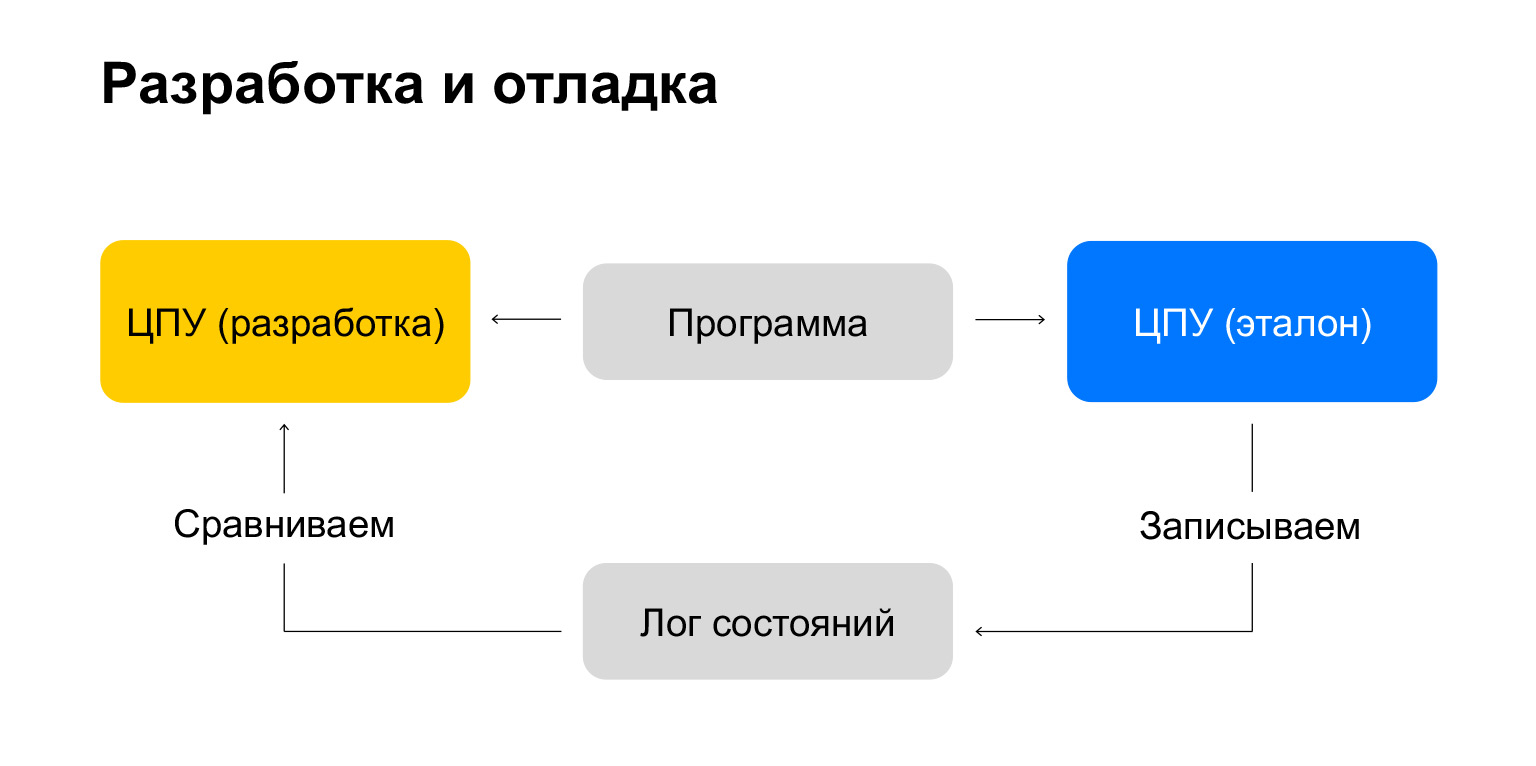
There is a superb and wonderful way! We take two CPUs. The first is the one we make, the second is the reference CPU, we know for sure that it works well. For example, there is an emulator for the NES, the nintendulator, which is considered such a benchmark for CPUs.
We take a certain test program, execute it on the reference CPU and write the processor state to the state log for each command. Then we take this program and execute it on our CPU. And each state after each command is compared with this log. Super idea!
Of course, we don't need a CPU reference. We just need a program execution log. This log can be found on Nesdev. In fact, a processor emulator can be written, I don’t know, in a couple of days on the weekend - it’s just superb!
And that's all. We take the log, compare the state, and we have an interactive test. We execute the first command, it is not implemented in the processor that we are developing. We implement it, go to the next line of the log and implement it again. Super fast! Allows you to move quickly.
NES architecture
We now have a CPU, which is essentially the heart of our computer. And we can see what the architecture of the NES itself is made of and how such complex composite computer systems are made. Because if you think about it, well, there is a CPU, there is memory. We can receive values, record, etc.

But in the NES, in any set-top box, there is also a screen, sound devices, etc. We need to learn to work with peripherals. You don't even need to learn anything new for this, the concept of our bus is enough. This is probably the second such brilliant idea, a brilliant discovery that I made for myself in the process of writing an emulator.
Let's imagine that we take our memory, which was 64 kilobytes, and split it into two 32 kilobytes ranges. In the lower range there will be a certain device, which is an array of bulbs, as in the picture with this board.
Let's say that when writing to this junior 32-kilobyte range, the light will turn on or go out. If we write there the value 1, the light comes on, if 0 - go out. At the same time, we can read the value and understand the state of the system, understand which picture is displayed on this screen.
Again, in the upper range of addresses, we put ordinary memory in which the program is located, because we need an address in the upper range during the reset procedure.
This is actually a super genius idea. To interact with peripherals, no additional commands are needed, etc. We just write to good old memory, as before. But at the same time, the memory can already be additional devices.

We are now fully prepared to take a look at the NES architecture. We have a CPU and its bus, as usual. There are two additional kilobytes of memory. There is an APU - a sound output device. Unfortunately, now we will not consider it, but everything is super cool there too. And there is a cartridge. It is placed in the high range and supplies program data. He also supplies these graphs, now we will consider. The last thing on the CPU bus is the PPU, picture processing unit, such a proto-video card. If you wanted to learn how to work with video cards, we are now even going to learn how to implement one.
The PPU also has its own bus, on which the name tables, palettes and graphic data are shifted. But the graphic data is supplied by the cartridge. And then there is the object's memory. This is the architecture.

Let's see what a cartridge is. This is a much cooler idea than the CD when you consider that it is from the past.
Why is she cool? On the left we can see the cartridge of the American region, the famous game Zelda, if anyone has not played - play, super. And if we disassemble this cartridge, we will find microcircuits in it. There is no laser disk, etc. Usually these chips just contain some data. Also, the cartridge directly cuts into our computer system, into the CPU and PPU bus. It allows you to do amazing things and enhance the user experience.
There is a mapper on board the cartridge, it fills with the translation of addresses. Let's say we have a big game. But the NES has only 32 kilobytes of memory that it can address for the program. A game, let's say, is 128 kilobytes. mapper can, on the fly, during program execution, replace a certain range of memory with completely new data. We can say in the program: load us level 2, and the memory will be directly replaced, almost instantly.
Plus there are funny things. For example, the mapper can supply chips that expand soundtracks, add new ones, etc. If you've played Castlevania, listen to what the Japanese region's Castlevania sounds like. There is an additional sound, it sounds completely different. In this case, everything is performed on the same hardware. That is, this idea is more akin to the one when you bought a video card, plugged it into a computer, and you have additional functionality. It's the same here. That's great. But we are stuck with CDs.

Let's move on to the final part - let's look at how this image output device works. Because if you want to make an emulator, the minimum program is to make a processor and this thing to watch how pictures and video games look.
Let's start with the top-level entity - the picture itself. It has two plans. There is a foreground where more dynamic entities are placed and a background where more static entities like a scene are placed.
You can see the split here. On the left is the same famous Castlevania game, so our entire journey to PPU will happen with Simon Belmont. Together with him, we will consider how everything works.
There is a background, columns, etc. We see that they are drawn in the background, but at the same time all the characters - Simon himself (left, brown) and ghosts - are already drawn in the foreground. That is, the foreground exists for more dynamic entities, and the background exists for more static ones.

A picture on a bitmap display consists of pixels. Pixels are just colored dots. At the very least, we need colors. The NES has a system palette. It consists of 64 colors, which is unfortunately all the colors the NES is capable of reproducing. But we cannot take any color from the palette. For custom palettes, there is a specific range in memory, which, in turn, is also split into two such sub-ranges.
There is a range of background and foreground. Each range is divided into four palettes of four colors. For example, background, zero palette consists of white, blue, red. And the fourth color in each palette always refers to a transparent color, which allows us to make a transparent pixel.

This range with palettes is no longer located on the CPU bus, but on the PPU bus. Let's see how we can write data there, because we don't have access to the PPU bus through the CPU bus.
Here we again come back to the idea of memory mapped I / O. There are addresses 0x2006 and 0x2007, these are hexadecimal addresses, but they are just numbers. And we write like this. Since our address is 16-bit, we write the address into the ox2006 address register in two approaches of eight bits and then we can write our data through the address 0x2007. Such a funny thing. That is, in fact, we need to perform three operations in order to at least write something to the palette.

Excellent. We have a palette, but we need structures. Colors are always good, but bitmaps have a certain structure.
For graphics, there are two tables of four kilobytes each containing tiles. And all this memory is a kind of atlas. Previously, when everyone used a raster image, they made a large atlas, from which they then selected the necessary images through the background-image by coordinates. Here's the same idea.
Each table has 256 tiles. Again, funny numerology: exactly 256 allows you to specify one byte, 256 different values. That is, in one byte we can specify any tile that we need. It turns out two tables. One table for backgrounds, another for foreground.

Let's see how these tiles are stored. It's a funny thing here, too. Let's remember that we have four colors in our palette. Numerology again: a byte has eight bits, and a tile is eight by eight. It turns out that with one byte we can represent a strip of a tile, where each bit will be responsible for some color. And with eight bytes, we can represent a full-fledged eight by eight tile.
But there is one problem here. As we said, one bit is responsible for color, but it can represent only two values. Tiles are stored in two planes. There is a plane of the most significant and least significant bit. To get the final color, we combine data from both planes.
You can consider - here, for example, the letter "I", the lower part, there is the number "3", which turns out like this: we take the plane of the least significant and most significant bits and get the binary number 11, which will be equal to the decimal 3. Such a funny data structure.
Background
Now we can finally render the background!

There is a table of names for it. We have two of them, each of 960 bytes, each byte refers us to a specific tile. That is, the tile identifier is indicated in the previous table. If we represent these 960 bytes as a matrix, we get a 32 by 30 tile screen. The NES resolution will be 256 pixels by 240 pixels.
Excellent. We can write tiles there. But as you may have noticed, the tiles do not indicate the palette with which they should be displayed. We can display different tiles with different palettes, and we also need to store this information somewhere. Unfortunately, we only have 64 bytes per name table for storing palette information.
And this is where the problem arises. If we split the table further so that there are only 64 values, we get squares of four by four tiles, which look like such a red square. This is just a huge portion of the screen. She would be subordinated to one palette, if not for one but.
As we remember, there are four palettes in the sub-palette, and we only need two bits to indicate the one we need. Each of these 64 bytes copies the palette information for a four-by-four grid. But this grid is still split into such subgrids two by two. Of course, there is a limitation here: a two-by-two grid is tied to one palette. These are the limitations in the world of displaying backgrounds on Nintendo. Fun fact, but in general it doesn't really interfere with games.

There is also scrolling. If we recall, for example, "Mario" or Castlevania, then we know: if in these games the hero moves to the right, then the world seems to unfold along the screen. This is done by scrolling.
Recall that we have two name tables that already encode two screens. And when our hero moves, we kind of add data to the table of names that follow. Right on the fly, when our hero moves, we fill in the table of names. It turns out that we can indicate from which tile in the table of names we need to start displaying data, and we will expand it in strips. The whole trick of scrolling is reading from the two name tables.
That is, if we go beyond one table of names horizontally, then we begin to automatically read from another, etc. And do not forget, again, to fill in the data.
By the way, scrolling was a pretty big thing at the time. John Carmack's first accomplishments were in the field of scrolling. Check out this story, it's pretty funny.
Foreground
And the foreground. In the foreground, as we said, there are dynamic entities, and they are stored in the memory of objects and attributes.

There are 256 bytes that we can write 64 objects to, four bytes per object. Each object encodes X and Y, which is the pixel offset on the screen. Plus tile address and attributes. We can prioritize the background, see the picture below? We can specify the palette. Priority over background tells the PPU that the background should be drawn on top of the sprite. This allows us to place Simon behind the statue.
We can also make the orientation, turn it past any axis, for example, horizontal, vertical, like the letter "I" in the picture. We write in approximately the same way as the palette: through the address 0x2003, 0x2004.
Finally, the final. How do we render foreground objects?
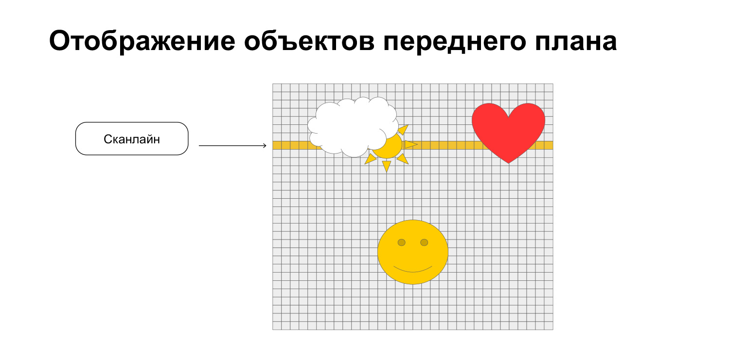
The picture unfolds along lines called scanlines, this is a television term. Before each scanline, we simply grab eight sprites from object and attribute memory. No more than eight, only eight are supported. There is also such a limitation. We just display them line by line, like here, for example. On the current scanline, in yellow, we display a cloud, a sun and a heart in a stripe. And the smiley is not displayed. But he is still happy.
Check out the One Lone Coder super channel . There is the programming process itself, in particular - programming the NES emulator. And Nesdev contains all the information on emulation - what it consists of, etc. The final link is the code of my emulator . Take a look if interested. Written in TypeScript.
Thanks. Hope you enjoyed it.