Part 1. Beginning
1.1 Introduction and problem statement
At MTS, we centrally control the quality of data transmission networks or, more simply, the transport network (not to be confused with the logistics transport network), hereinafter referred to as TS. And, within the framework of our activity, we constantly have to solve two main tasks:
- Degradation of client (in relation to the vehicle) services has been detected - it is necessary to determine the path of their connection through the vehicle, and find out whether any part of the vehicle is the cause of the degradation of services. Further, we will call this the Direct Problem.
- Degradation of the quality of the transport channel or channel sequence is detected - it is necessary to determine which services depend on this channel / channels to determine the impact. Further, we will call this the Inverse Problem.
TS services are understood as any connection of client equipment. These can be base stations (BS), B2B clients (using MTS TS for organizing access to the Internet and / or overlay VPN networks), fixed access clients (so-called broadband access), etc. etc.
We have at our disposal two centralized information systems:
| Performance Monitoring System | Network Parameter and Topology Data |
|---|---|
 |
 |
| Metrics, KPI TS | Configuration parameters, L2 / L3 channels |
Any transport network is inherently a directed graph in which each edge has a non-negative bandwidth. Therefore, from the very beginning, the search for solutions to these problems was carried out within the framework of graph theory.
First, the issue of comparing the quality indicators of the TS and services with the TS topology was solved by literally combining and presenting the topology and quality data in the form of a network graph.
The view of the graph formed according to the topology and performance data was implemented using the open source Gephi software . This made it possible to solve the problem of automatic representation of the topology, without manual work on its updating. It looks like this:
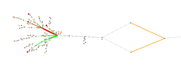
Here, the nodes are, in fact, the nodes of the TS (routers, switches) and the basic ones, the edges are the channels of the TS. Color coding, respectively, denotes the presence of quality degradations and the treatment status of these degradations.
It would seem that it is quite clear and you can work, but:
- The direct problem (from service to service path) can be solved quite accurately only provided that the TS topology itself is quite simple - a tree or just a serial connection, without any rings and alternative routes.
- The inverse problem can be solved under a similar condition, but at the same time it is impossible to solve this problem at the level of aggregation and the network core, since these segments are governed by dynamic routing protocols and have many potential alternative routes.
Also, keep in mind that, in general, the network topology is much more complicated (the above fragment is circled in red):

And this is not the smallest segment - there is much more and more complex in topology:

So, this option was suitable for meditative analysis of individual cases, but in no way for streamlined work and, moreover, not for automating the solution of direct and reverse.
Part 2. Automation v1.0
Let me remind you what tasks we solved:
- Determining the path of the service through the vehicle - Direct task.
- Determination of dependent services from the TC channel - Inverse problem.
2.1. Transport services for Base Stations (BS)
Generally, the organization of transport from the central node (controller / gateway) to the BS looks like this:

On the segments of aggregation and the core of the TS, connections are made through transport services of the MPLS network: L2 / L3 VPN, VLL. On access segments, connections are performed, as a rule, through dedicated VLANs.
Let me remind you that we have a database where all the actual (within a certain period) parameters and topology of the vehicle lie.
2.2. Dial-up segment solution (access)
We take data about the VLAN of the BS logical interface, and step by step we “go” through the links, the ports of which contain this Vlan ID, until we reach the border router (MBN).

To solve such a simple problem statement, I ended up having to:
- Write an algorithm for step-by-step tracing of the "propagation" of VlanID from BS through the channels of the aggregation network
- Consider existing data gaps. This was especially true of the joints between the nodes on the sites.
- In fact, write an SPF algorithm in order to drop dead-end branches at the end that do not lead to the MVN router.
The algorithm came out of one main process and seven sub-processes. It took 3-4 weeks of pure working time to implement and debug it.
In addition, we were given special pleasure ...
2.2.1. SQL JOIN
Due to its structure, the relational model for traversing the graph requires an explicit recursive approach with join operations at each level, while repeatedly traversing one set of records. This, in turn, entails a degradation in system performance, especially on large data sets.
For obvious reasons, I cannot cite the contents of queries to the database here, but evaluate - each "ledge" in the query text is the connection of the next table, which is needed for, in this case, obtaining a unified correspondence between Port and VlanID:

And this request is for obtaining, in a unified form, VlanID cross-connections inside the switch:

Considering that the number of ports was several tens of thousands, and the VLAN was 10 times more, all this was very reluctant to toss and turn. And such requests had to be made for each node and VlanID. And “unload everything at once and calculate” is impossible, since it is a sequential computation of the path c with step-by-step operations that depend on the results of the previous step.
2.3. Determining the Service Path in Routed Segments
Here we started with one MVN vendor whose management system provided data on the current and standby LSPs over the MPLS segment. Knowing the Access interface that was docked with the access (L2 Vlan), it was possible to find the LSP and then, through a series of requests to the NBI system, get the LSP path consisting of routers and links between them.

- Similar to the switched segment, the description of unloading the LSP path of the MPLS service resulted in an algorithm with already 17 subroutines.
- The solution worked only on segments served by this vendor
- It was necessary to decide the definition of the joints between MPLS services (for example, in the center of the segment there was a general VPLS service, and either EPIPE or L3VPN diverged from it)
We worked on the issue for other MVN vendors, where there were no control systems, or they did not provide data on the current LSP passage in principle. We found a solution for several, but - the number of LSPs passing through the router is no longer the number of VanIDs, which is registered on the switch. Delaying such a volume of data “on demand” (after all, we need operational information) - there is a risk of putting the hardware down.
In addition, additional questions arose:
- – , , . .. – MPLS .
- , LSP, . . .
2.4. .
The received data about the paths of services connection must be written down somewhere, so that later we can refer to them when solving our Direct and Inverse problems.
The option with storing in a relational database was immediately ruled out: is it so difficult to aggregate data from many sources so that later it can be sorted into the next sets of tables? This is not our method. Moreover, remember about multi-storey joins and their performance.
The data should contain information about the structure of the service and the dependencies of its components: links, nodes, ports, etc.
As a test solution, the XML format and Native-XML DB - Exist were chosen.
As a result, each service was written to the database in the format (details are omitted for the sake of compactness):
<services>
	<service>
		<id>,<description>   (,  )
		<source>
		<target>    Z
		<<segment>>  L2/L3
			<topology>      (, /, )
		<<joints>>    (, /, )
	</service>
</services>
Data query for direct and inverse problems was performed using the XPath protocol:

All. Now the system is working - for a request with the name of the BS, the topology of its connection through the transport network is returned, for a request with the name of the node and port of the TS, a list of BSs that depend on it for connection is returned. Therefore, we made the following conclusions ...
2.5.

Instead of heading on the findings of Part 2
2.5.1. For the switched segment (networks on L2 Ethernet switches)
- Complete data on topology and Port - VlanID correspondence is required. If there is no VlanID data on some link, the algorithm stops, the path was not found
- Multilevel unproductive queries against a relational database. When a new vendor appears with its own specifics, parameters - adding requests at all stages of work
2.5.2. For a routed segment
- Limited by the capabilities of the MVN SU to provide data on the topology of LSP MPLS services.
- – , .. LSP .
- LSP – ( , “” ).
2.5.3.
- , , , , ( – , ), , – .
- . 3-4 .
- , .. , MPLS .
- – , .
2.6. -
- , , .. – .
- , -
- (, VlanID)
After we assessed the possible options for the implementation of our wishes, we decided on the class of systems that would provide all this "out of the box" - this is the so-called. graph databases.
Although the last sentence is read as something linear and simple, given that previously none of us (and our IT specialists, as it turned out, either) had ever encountered such a database class, they came to the decision somewhat by accident: similar databases were mentioned (but did not understand) in the Big Data overview course. In particular, it mentioned the product Neo4j... Not only did it, judging by the description, satisfy all our requirements, it also has a completely free functional community version. Those. - not a 30-day trial, not cut off the main functionality, but a fully working product that you can slowly study. Not the last (if not the main) role in the choice was played by the wide support of graph algorithms .
Part 3. An example of the implementation of the direct problem in Neo4j
In order not to drag out the linear narration of how the TS model is implemented in the Neo4j graph database, we will immediately show the final result with an example.
3.1. Tracing the path of the Iub interface for 3G BS

The path of connecting the service passes through two segments - a routed MVN, and a switched radio relay line (radio relay stations work as Ethernet switches). The path through the RRL segment is determined in the same way as described in Part 2 - by the passage of the BS interface VlanID along the RRL segment to the MVN border router. The MVN segment connects the border (with the RRL segment) router - with the router to which the BS controller (RNC) is connected.
Initially, from the Iub parameter, we know exactly which MVN is the gateway for the BS (boundary MVN), and which controller is served by the BS.
Based on these initial conditions, we will build 2 queries to the database for each of the segments. All queries to the database are built in the Cypher language... In order not to be distracted by its description now, think of it simply as “SQL for graphs”.
3.1.1. RRL segment. VlanID path
Cypher request for tracing the service path based on the available VlanID and L2 topology data:
| Fragment of a Cypher query
(WITH construction - passing the results of one stage of the query to the next (pipelining of processing)) |
Intermediate query results (visual representation in the Neo4j console - " Neo4j Browser ") |
|---|---|
Obtaining the BS and MVN nodes between which the Iub service path will be searched
|
 |
Receiving Vlan nodes of BS interface Iub
|
 |
We select the nodes of the vehicle on the same site with the BS, on the ports of which VlanID Iub BS is registered
|
 |
using Dijkstra's algorithm, we find the shortest path from the VlanID of the TS of the site of the BS to the boundary MVN
|
 |
From the Vlan chain, we get a list of nodes, ports, and connections between ports, which, in the end, will be the way to connect the Iub service from the BS to the border router
Result: |
|
 |
|
As you can see, the path has been obtained, even despite a partial lack of data. In this case, there is no information about the junction of the BS port with the port of the radio relay station.
3.1.2. RRL segment. L2 topology path
Let's say an attempt is made in clause 3.1.1. failed due to complete or partial absence of data on the VlanID parameter. In other words, such a continuous chain reaching the MVN node is not built:
Then you can try to define the service connection as the shortest path to the MVN according to the L2 topology:
Result: |
 |
As you can see, the same result is obtained. Here, the lack of information about the junction of the BS with the RRS is made up for by the passage of communication through the object (node) of the site on which they are located. Of course, the accuracy of this method will be less, since in general, Vlan may not be registered along the shortest path suggested by Dijkstra's algorithm. But the request consists of only two operations.
3.1.3 MVN segment. Tracing the path from the boundary MVN to the controller
Here we also use Dijkstra's algorithm.
One path with minimal cost
|
 |
Top 2 paths with the lowest cost (main + alternative)
|
 |
Top 3 paths with minimum cost (main + two alternatives)
|
 |
Likewise, in this case, there is no information about the direct joints of the MVN with the RNC. But this does not prevent you from building a service path, even if it is assumed by the algorithm (more on that later).
3.2. Labor costs
The implementation of the Direct Problem, shown now, is strikingly different from the approach "develop an algorithm, program, method of storing and retrieving results" - it all comes down to "write a query to the database". Looking ahead, we note that the entire cycle from developing a simple graph model, loading data into Neo4j from a relational database, writing queries, and until the result was obtained, took a total of one day.
3-4 months vs 1 day !!! This was the last reason for the final departure to the graph database.
Part 4. Graph database Neo4j and loading data into it
4.1. Comparison of relational and graph databases


4.2. Data model
The basic model of the TS presentation up to the L3 topology level inclusive:

Of course, the model is more extensive than the one presented, and also contains MPLS services and virtual interfaces, but for simplicity, we will consider a limited fragment of it.
In such a model, the relationship between two network elements of the same region can be represented as:

4.3. Loading data
We load data from the database of the parameters and topology of the vehicle. To load into Neo4j from the SQL database, the APOC library is used - apoc.load.jdbc , which takes as input a connection string to the RDBMS and the text of an SQL query, and returns a set of strings that are mapped to nodes, links, or parameters through CYHPER expressions. Such operations are performed layer by layer for each type of model object.
For example, a pass for loading / updating nodes representing network elements (Nodes):
|
Calling the procedure apoc.load.jdbc,
getting a dataset |
|
For each row from the dataset
by the region and site code, nodes are searched that represent the corresponding sites |
|
For each site object, the
associated network elements (node) are updated . The MERGE + SET instruction is used, which updates the parameters of the object if it already exists in the database, if not , then it creates the object. The parameters of the Node node and its connections with the PL node are also recorded. |
And so on - across all levels of the TS model.
The Updated field is used to control the relevance of the data in the column - objects that are not updated for longer than a certain period are deleted.
Part 5. Solving the inverse problem in Neo4j
When we first started out, the expression "service trace" first brought up the following associations:

That is, that the current path of the service is traced directly, at a given time.
This is not exactly what we have in a graph database. In the GDB, a service is traced according to the relationships of objects that determine its configuration in each involved network element. That is, a configuration is represented in the form of a graph model , and the resulting trace is a pass over the model representing this configuration.
Since, unlike the switched segment, the actual service routes in the mpls segment are determined by dynamic protocols, we had to accept some ...
5.1. Assumptions for Routed Segments
Because from the configuration data of mpls services, it is not possible to determine their exact path through the segments controlled by dynamic routing protocols (especially if Traffic Engineering is used) - for the solution, Dijkstra's algorithm is used.
Yes, there are management systems that can provide the actual path of service LSPs via the NBI interface, but so far we have only one such vendor, and there are more than one vendors in the MVN segment.
Yes, there are systems for analyzing routing protocols within the AS, which, by listening to the exchange of IGP protocols, can determine the current route of the prefix of interest. But there are such systems - like a downed Boeing, and given that such a system needs to be deployed on all ASs of the same mobile backhole - the cost of the solution, together with all licenses, will be the cost of a Boeing shot down by a cast-iron bridge tied to the Angara rocket when fully refueled. And this is despite the fact that such systems do not completely solve the problem of accounting for routes through several AS using BGP.
Therefore - so far. Of course, we added several props to the conditions of the standard Dijkstra's algorithm:
- Accounting for the status of interfaces / ports. The disconnected link increases in cost and goes to the end of the possible path options.
- Accounting for the backup link status. According to the Performance Monitoring system, the presence of only keepalive traffic in the mpls channel is calculated, respectively, the cost of such a channel also increases.
5.2. How to solve the inverse problem in Neo4j
Reminder. The inverse task is to obtain a list of services that depend on a specific channel or node of the transport network (TS).
5.2.1. Switched L2 segment
For the switched segment, where the service path and the service configuration are practically the same, the problem can still be solved through CYPHER requests. For example, for a radio relay flight from the results of solving the Direct problem in clause 3.1.1., We will make a request from the radio relay link modem - we will "expand" all Vlan chains that pass through it:
match (tn:node {name:'RRN_29_XXXX_1'})-->(tn_port:port {name:'Modem-1'})-->(tn_vlan:vlan)
with tn, tn_vlan, tn_port
call apoc.path.spanningTree(tn_vlan,{relationshipFilter:"ptp_vlan>|v_ptp_vlan>", maxLevel:20}) yield path as pp
with tn_vlan,pp,nodes(pp)[-1] as last_node, tn_port
	match (last_node)-[:vlan]->(:port)-->(n:node)
	return pp, n, tn_port
The red node indicates the modem whose Vlan we are deploying. 3 BSs were circled on which, as a result, the deployment of transit Vlan with Modem1 led.

This approach has several problems:
- For ports, the configured Vlan must be known and loaded into the model.
- Due to possible fragmentation, the Vlan chain does not always output to the terminal node
- It is impossible to determine if the last node in the Vlan chain belongs to a terminal node or if the service actually continues on.
That is, it is always more convenient to trace a service between end nodes / points of its segment, rather than from an arbitrary “middle”, and from one OSI layer.
5.2.2. Routed segment
With a routed segment, as already described in clause 5.1, there is no need to choose - there are no means to solve the inverse problem based on the data of the current configuration of some intermediate MPLS link - the configuration does not explicitly define the service trace.
5.3. Decision
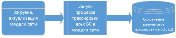
The decision was made as follows.
- Full loading of the vehicle model is carried out, including BS and controllers
- For all BS, the direct problem is solved - tracing of Iub, S1 services from the BS to the boundary MVN, and then from the boundary MVN to the corresponding controllers or gateways.
- Trace results are written to a regular SQL database in the format: BS name - an array of service path elements
Accordingly, when accessing the database with the condition Node TS or Node TS + Port, a list of services (BS) is returned, the path array of which contains the required Node or Node + Port.
Part 6. Results and conclusions
6.1. results
As a result, the system works as follows:

At the moment, to solve the direct problem, i.e. when analyzing the causes of degradation of individual services, a web application was developed that shows the trace result (path) from Neo4j, with superimposed data on the quality and performance of individual sections of the path.

To obtain a list of services that depend on nodes or channels of the TS (solution of the inverse problem), an API has been developed for external systems (in particular, Remedy).
6.2. conclusions
- Both solutions raised the automation of the analysis of the quality of services and the transport network to a qualitatively new level.
- In addition, in the presence of ready-made data on the routes of BS services, it became possible to quickly provide data for business units on the technical possibility of including B2B customers at specific sites - in terms of capacity and quality of the route.
- Neo4j has proven itself to be a very powerful tool for solving network graph problems. The solution is well documented , has broad support in various developer communities , and is constantly evolving and improving.
6.3. Plans
We have plans:
- expansion of technological segments modeled in the Neo4j database
- development and implementation of tracing algorithms for broadband services
- increase in server platform performance
Thank you for attention!