As it usually happens with me, when an idea comes up, it is pondered over, and then (Ostapa begins to bear) it becomes overgrown with additional functions that I did not initially think about. These thoughts ignite the passion of creativity and the process begins.
So, it all started with the fact that during a walk it was necessary to see the current time in order to know the time of the walk ...
It is not convenient to watch the time on the phone every time, and I don’t wear a watch for a long time. This means that you need an indicator in a convenient place that displays the current time, as well as the walking time, so as not to count every time. Walking in the dark, the child is not visible in the stroller, which means you need to equip the cradle with lighting. Also, when driving in places without artificial lighting, it would be nice to have a headlight ahead to illuminate the path. In the cold season, I would like to know the air temperature in the cradle, as well as the air temperature outside.
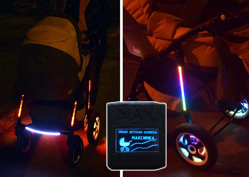
To ensure the visibility of the stroller at night, when moving around the streets, there was an idea to equip the stroller frame with LED lighting. And so that the backlighting was not boring, I used "smart" LEDs for the frame and wheels.
The indicator and control buttons should be in an accessible place, and in my case this is the stroller frame.
The power source of the device must ensure the system is operational with the decorative lighting and headlights on. Also needs to be charged from USB.
These were the main functions that I wanted to bring to life. But the thought went further. I wanted to know the distance that the wheelchair traveled during the current walk, for the day, for the entire time. Also the current driving speed.
Once I did not notice a flat tire and drove home for 4 km on a flat tire. I thought about monitoring tire pressure.
Well, in the end, it's time to think about the safety of the stroller itself. For this I planned to use a GPS / GLONASS receiver and a GSM modem.
Full implemented functionality of a smart baby stroller:
- ;
- GPS/;
- ;
- ;
- ;
- , ;
- ;
- ;
- ;
- ;
- (TPMS);
- ;
- ;
- GPS/ ;
- GSM- .

Since the circuit contains many elements and a capacious battery, it was decided to implement the device in two blocks - the main and the display unit. The main unit is shown in Fig. 1, the display unit is in Fig. 2.

Fig. 1. Schematic diagram of the main unit of the device
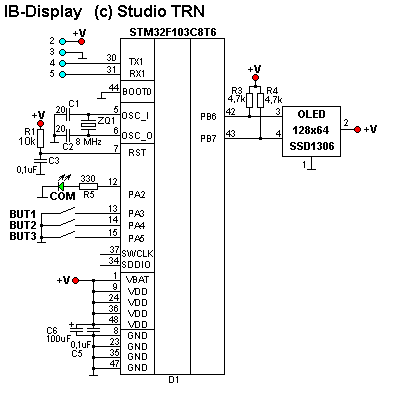
Fig. 2. Schematic diagram of the display unit
ARM was chosen as the controller of the D1 device. The battery charging unit is implemented on microcircuits D3, D4 according to the standard switching scheme. The charge comes from the phone charger via a USB connector. Also, optionally, the battery is charged from the on-board network with a voltage of 6-20 volts. The temperatures inside the cradle, outside and the battery are implemented on the DS18B20. Because the cradle can be removed from the frame for the purpose of transportation or replacement with a summer version, then a connector is attached to the cradle, which disconnects the thermometer unit and the backlight inside the cradle from the device.
A GPS / GLONASS receiver was used to determine local coordinates and the exact current time. When a GPS signal is available, the system time is recorded in D2. In case of poor reception of GPS / GLONASS signals, the current time is not corrected, but the D2 watch keeps pace.
D14 (EEPROM 24CL16) is used to store data of various statistics.
Decorative illumination is made on "smart" WS2812b LEDs. All lighting elements, including the headlight and wheels, are lined up in one information chain.
The informant block is assembled on elements D6, D7, D8. The circuit is copied from a Chinese MP3 module based on the JQ6500. MP3 music fragments are sewn into Flash D7 via USB.
ADXL345 is used as accelerometer D9. Data from the accelerometer is used to monitor irregularities on the road, as well as for security purposes.
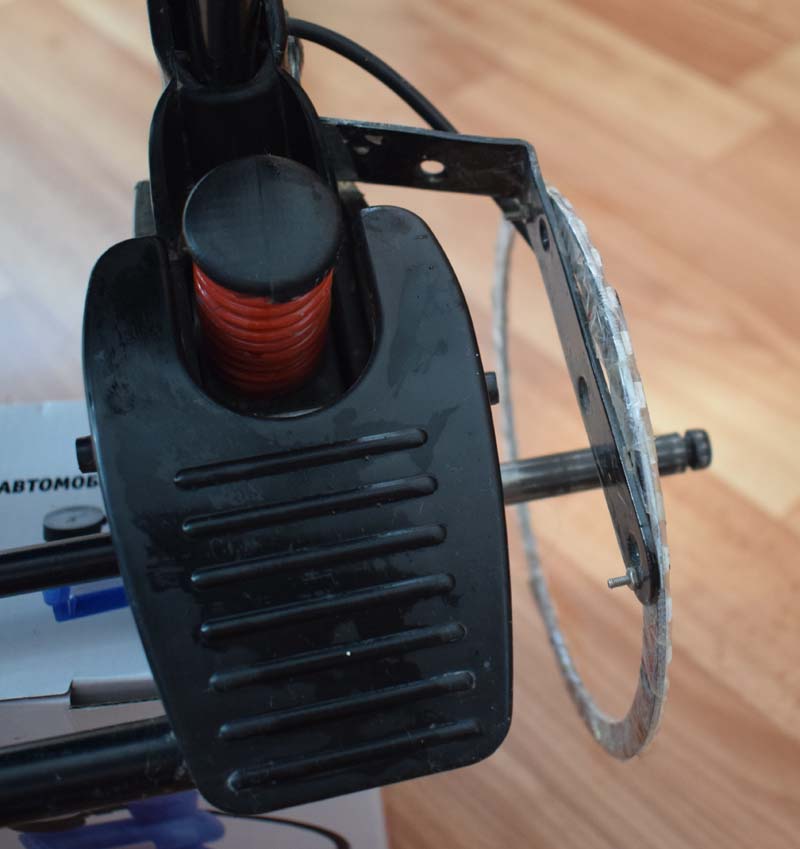
The tire pressure monitoring subsystem has fascinated me for a long time and therefore was awarded a separate article [1]... The fact is that the Chinese TPMS that I use in my device has a receiving unit, which is designed to control pressure in the range of 1.1 atm - 3.2 atm. The standard system notifies pressure outside this range with a beep every time the sensors are polled. The sensors are polled periodically after about 30-60 seconds in normal operation. Therefore, it is not possible to simply put the standard unit in the stroller. And it’s not interesting. It is much more interesting to study the protocol and implement it into your system, which was done. The system consists of four external sensors that are screwed onto the wheel fitting.

The sensors are wireless, periodically transmit information about the wheel pressure and air temperature in the wheel. The broadcasting frequency of the sensors is 433.92 MHz with FSK modulation. To capture signals from sensors, a transceiver module on an SI4432 microcircuit was used.
To transfer data to the GPS tracking site, a GSM modem SIM800C is used. Tracking is used for the anti-theft security system of a wheelchair, as well as for storing walking tracks for history.
The main unit and the display unit are made on printed circuit boards and are shown in Fig. 3. and fig. 4.

Fig. 3. External view of the main unit board of a "smart" baby carriage

Fig.4. Display board appearance
The device uses an OLED display on the SSD1306 controller. The display is small and fits on the handle of the stroller. But this is also a big minus, because when the stroller vibrates during movement, the small print is not visible. Therefore, the main information screens are displayed in large print.


The main unit and the display unit are connected by a serial port, which reduces the number of wires.
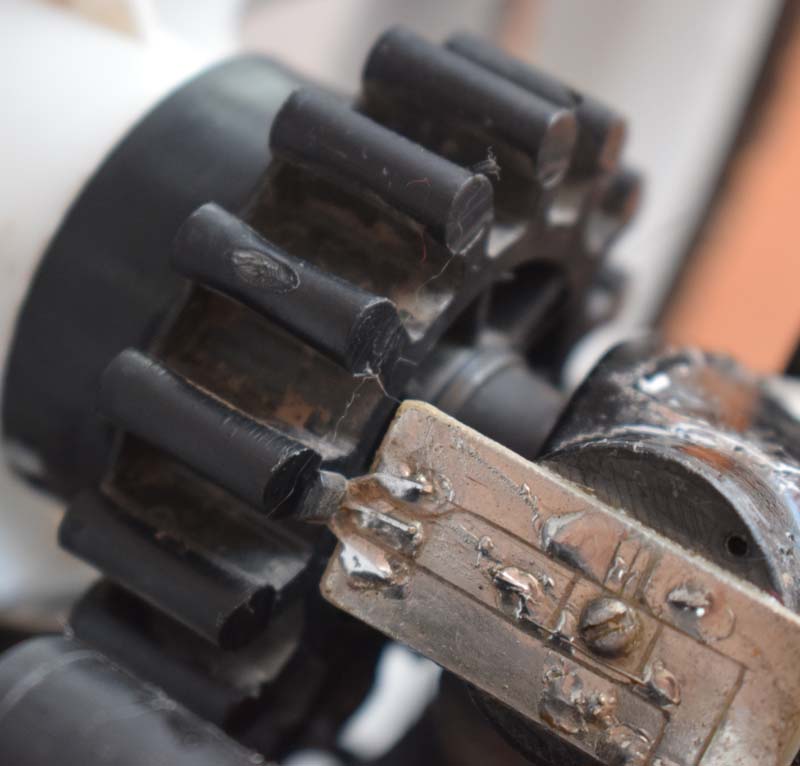
Hall sensors are used as a speed sensor and a sensor for activating the brake system. The sensors are mounted on a separate board on the wheel, varnished from moisture and sealed.

The decorative lighting LEDs are mounted on a frame in aluminum profiles with light filters and are also sealed from the outside. The LED rings are IP30 rated, so they had to be sealed against moisture.


All wires are laid inside the stroller frame profile, there are transitions at the bend points when the stroller is folded.


The system is constantly in standby mode. All secondary devices are disabled with the VT3 key. The controllers of both blocks operate at a reduced frequency and unnecessary ARM peripherals are also disabled. As soon as a certain sequence of buttons is pressed (protection against being turned on by a stranger), the system wakes up, the VT3 key is turned on, and the modules are initialized.
All emergency events are accompanied by pop-up messages on the display and the corresponding informant melody.
Description of the software part of the device
The system is initially turned on by a hidden toggle switch and the system is put into standby mode. Further switching on and off the system is done by pressing a certain combination of buttons from the display unit.
When the system is turned on in the operating mode, the controllers switch to a higher frequency, various subsystems are initialized, and a start melody is played.
Further, each block starts its work, the data is processed and events are generated to inform about alarms or when values go beyond the specified limits.
Setpoints for tire pressure, axle acceleration, overspeeding and others are set once in the program. It makes no sense to dynamically change these values from the menu.
All data that is collected by the system is transmitted to the display unit, which forms images of information screens. Also, commands for the main unit to control peripherals come from the display unit.
When power is supplied to the GPS / GLONASS module, it starts collecting information from satellites and, having collected the necessary data, starts analysis. When the receiver issues a flag of data validity, the current time, date and coordinates are taken from the GPRMC / GNRMC package. The time is recorded in the RTC DS3231. In the open sky, when you first turn it on, the search for satellites takes about two minutes. The GPS / GLONASS receiver used has a "prediction procedure" for two weeks. Each time it is turned on, it does not need to collect a large amount of data, therefore, adequate coordinates are issued within a few seconds. This is provided that during the time since the last turn on the receiver has not moved a great distance from the previous point, and also if there is a backup battery.
The battery charging system is hardware-based and does not depend on the system state. But signals about the charging process go to the controller for analysis. When the charger is connected, the controller sees that charging has started. To calculate the duration of charging, as well as the time of the last charge, in order to keep statistics on the battery, the controller briefly turns on the peripheral enable key, reads the time, accesses the EEPROM and turns off the key. Upon completion of charging, similar actions are performed, but the end time of the charge is already recorded and the duration of charging is considered.

The temperature of the power supply, inside the cradle and outside, is monitored by a DS18B20 sensor. The polling procedure uses the UART port half-duplex mode and a DMA controller.
A modem is used to transfer data to the Internet. In order to save energy, the modem is turned on only when data transmission is needed. This happens either in the "anti-theft" mode, or when manually turned on.
Initially, the modem was not planned, but since the scheme already contained everything necessary for tracking, the modem simply begged for its use. But most interesting of all is the "anti-theft" system. The bottom line is to discreetly inform that a "hijacking" is taking place and transmit the coordinates of the wheelchair in real time. If the stroller is at home, then there is no need for "anti-theft", but if it is on the site outside the door and strangers can have access, then this mode is relevant.
So, the stroller is standing outside the door in standby mode. Only those users who know the sequence of pressing the buttons can turn on the stroller from the panel. The attacker is unaware of the presence of any system in the wheelchair. He just takes the stroller and rolls it away. The controller sees the presence of vibration from the accelerometer, also sees unauthorized wheel rotation and activates a silent alarm mode. It supplies power to all modules, initializes the modem and sends an alarm SMS to the owner's phone. It is recorded in cell # 1 of the SIM card. Then, it starts sending information about the LAC and CID of the base stations of the cellular operator to the tracking site. Upon arrival of adequate data on coordinates from the GPS / GLONASS receiver, they are included in the transmission packet.
The display is off at this time and no sound signals are heard.
If an authorized user accidentally forgot to turn on the system before walking, then turn off the system by turning it on correctly from the display panel and manually stop tracking.
There was a thought to make short signals during vibration in standby mode or to say some phrase, but then the attacker will know that the stroller is not easy and the appetite will increase, but he will be already prepared. Therefore, I stopped at silent mode.
There was no desire to create my own site for tracking. There is not enough time for anything. Therefore, I decided to see what is ready at the moment. I was very surprised when I found many tracking sites that allow you to connect a huge number of protocols of ready-made GPS trackers, and they can also bind your unique tracker protocol to their system, the admin guys will help with this. I did not want to strain the admins so that they adapt to my protocol and, therefore, it was decided to make an exchange protocol that sites already support. All the same, everything is written from scratch. Although on the site that I chose, the admins sent their homemade package format that their site accepts, I decided to stick with one of the standard ones. I liked the format of the MegaStek GPS tracker.
The format of the data transfer package from the tracker to the site is freely available. I ended up with a package like this:
$MGV002,351233456789,_TrackerName,R,200220,092552.000,A,3340.2243,N,02532.3216,E,00,04,00,1.20,02.5,15.9,280.06,02.312,250,02,0000,0000,25,1111,0105,1201 1201, 302 302,0401,23.4,07.2,,10,81.4,Timer;!It transmits a unique device ID, device name, coordinates, time, direction of movement, LAC, CID and more.
To see the position of your tracker, you need to register on the site. You can watch it through the website, or through the application on the phone. I really liked the application, it is not large, easy to navigate, there is a choice of maps. But the main thing is that you can register several trackers for free, and if you pay for an account, you get access to advanced functions. In general, the tracking services, today, made me very happy, compared to the previous period.

Working with the MP3 informer occurs via the UART by means of commands. MP3 files are written to the Flash informant through the software of a Chinese developer using a USB connection. Select files and send. More than enough. I initialize the JQ6500, set the volume level and then, upon arrival of events, a command is sent to play the file with the desired number. Before playing the file, the Mute signal is removed from the D8 digital power amplifier.
The commands are fully described in the description for the microcircuit, as well as in third-party libraries, so I will not dwell on them.
The tire pressure monitoring system, as described above, is based on standard wireless sensors, the signal from which is received in the system via the SI4432 transceiver. The transceiver is tuned to frequency, modulation, sensor deviation. Then the signal was planned to be analyzed programmatically, taking the raw packet from the air. But the presence of packet processing in this transceiver greatly facilitated the life of the main controller. I was able to tune the transceiver to receive bursts. The transceiver itself did all the necessary operations to receive the preamble, sync word, the data itself, and upon receiving the entire packet, it generated an interrupt. On interrupt, the main controller just read the received packet, analyzed the checksum and decoded the received data.
When the battery is low, the bezel and headlight are switched off to save energy.
If, in standby mode, a signal about wheelchair shaking comes from the accelerometer and if the rotation of the wheels is detected, but the device is not included in the normal operation mode, then the alarm mode is activated. All modules are activated, the display remains off. Those. from the outside it looks like everything is turned off. As soon as a signal from the GPS appears, the GSM modem sends an SMS about the alarm to the phone and starts broadcasting data on the current coordinates to the tracking site. Tire pressure data is also transmitted.

The current speed is determined by a Hall sensor on the wheel. Also, the speed is taken from the GPS / GLONASS module.
When the stroller is on the brake, the external illumination switches to the mode of alternating strobing of the left and right lights.
The device informs with a pop-up message on the display and a sound signal about exceeding the speed of more than 7 km / h, about irregularities on the road, about low air pressure in the wheels. Sound melodies mark every hour of the walk and every new astronomical hour.
The lighting inside the cradle of the stroller has the ability to change the brightness by long pressing and holding the button for turning on the lighting, but I do not use it for my needs.

The display unit has three buttons that respond to short and long presses. A short press on the ambient light button turns on the headlight, and a long press controls the different color schemes for the frame and wheel lighting.
The display shows all the necessary information about the operation of the device. Due to the small size of the display, information is displayed on multiple screens. Switching screens is carried out by a button on the display panel. There are two main screens on which the current time is displayed in large font and the walk screen, which displays the distance traveled during the walk, current speed, walking time, temperature inside the cradle. The remaining screens display diagnostic information on the operation of the tire pressure monitoring subsystems, accelerometer, modem, battery, and summary information. All images are formed in the controller buffer, from where they are transferred to the display at once by means of the DMA controller.


On the tire pressure monitoring screen, upon receiving a signal from any sensor, the corresponding wheel flashes in the picture of the stroller. If the pressure is below the set point, the temperature value blinks and the informant emits a periodic warning signal and a pop-up window on the display.


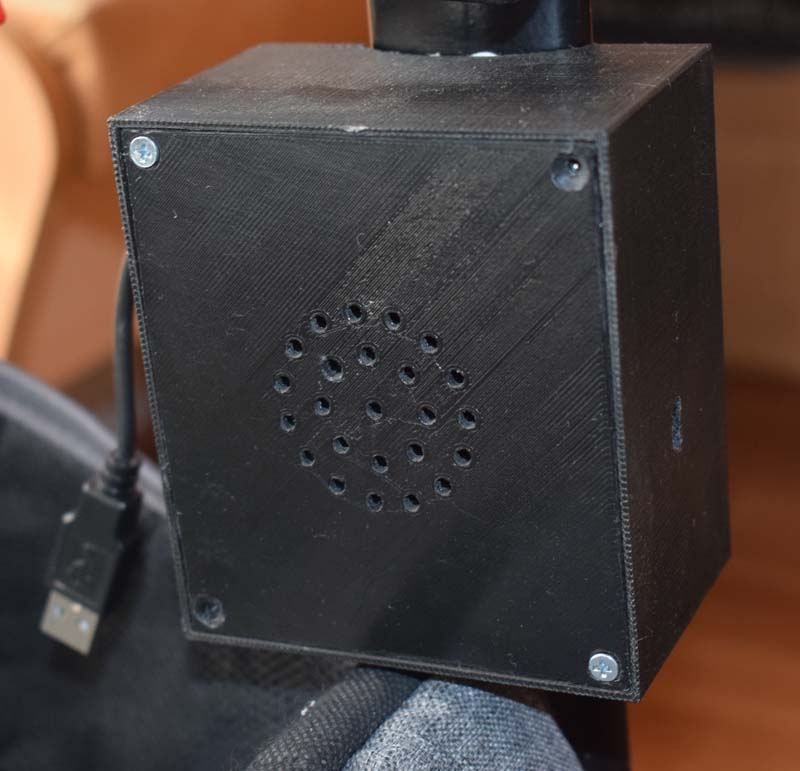
The battery charging screen contains information about the current battery voltage, the operating mode of the charger, and the date of the last charge. The stroller controller can be charged from any 5V voltage source, be it a smartphone charger or, as shown, from an outdoor light equipped with a USB socket.

The stroller has removable cradles: standard, in which the child only lies, and a stroller where he can also sit. Both cradles are equipped with LED lighting of the interior space and temperature sensors outside and inside. A detachable connection between the cradle and the main unit was provided, and the choice fell on a standard USB connector. When removing or replacing the cradle, first disconnect the connector, and then remove the cradle from the stroller frame. After installing the cradle, connect the connector. The controller knows which cradle is currently being used by the unique serial numbers of the thermometers.

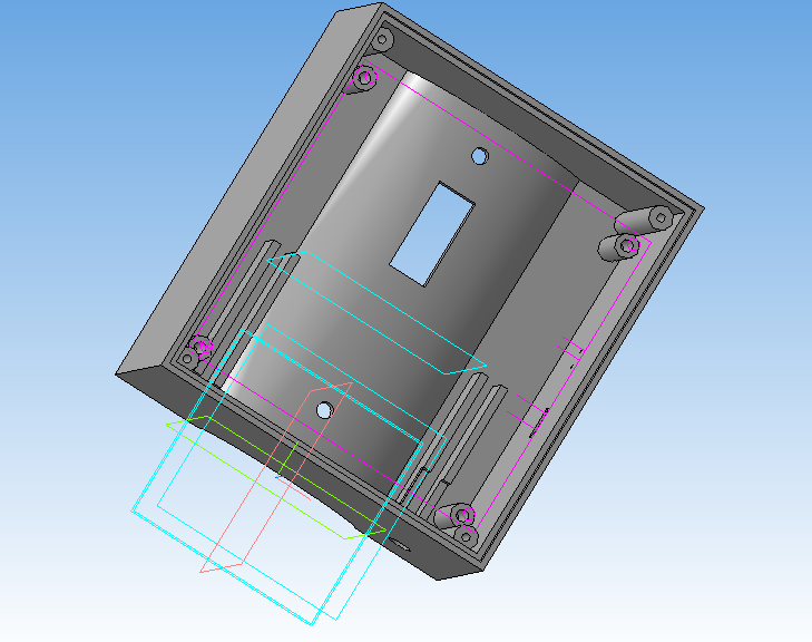
Housing
The bodies are modeled according to the curvature of the stroller frame surfaces and 3D printed.

Development
Can be used on bicycles, children's toy cars with 6..20 Volt on-board power supply.
You can use a different type of display by replacing only the display unit.
Conclusion
Due to a catastrophic lack of time, the implementation of this project took about 8 months.
During the development of the system, a lot was studied and tested on various modules and systems: the operation of the accelerometer, the exchange protocol of the GPS tracker, data transmission via GPRS modem, work with the transceiver, work with various ARM peripherals. It took a month to research only the TPMS system, but it was interesting.
Demonstration of system operation
Acknowledgments
I express my deep gratitude to friends and family who helped me in the implementation of this project.
Thanks to Eugene, Alexey, Natalia, Olga.
Links
1. Study of the protocol of the vehicle tire pressure monitoring system .