The sensors are available internally or externally. The inner ones are installed inside the tubeless tire cover, the outer ones are screwed onto the wheel fitting. A wheel with an internal sensor looks exactly the same as a wheel without a sensor. Such a wheel is easy to pump up. The external sensor is noticeable, it can be stolen and must first be unscrewed when inflating the wheel. It is also influenced by atmospheric phenomena.
To investigate the protocol of the TPMS system, I was prompted by the idea of installing such a system on a stroller to quickly monitor tire pressure.
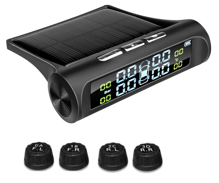
Fig. 1. TPMS system appearance
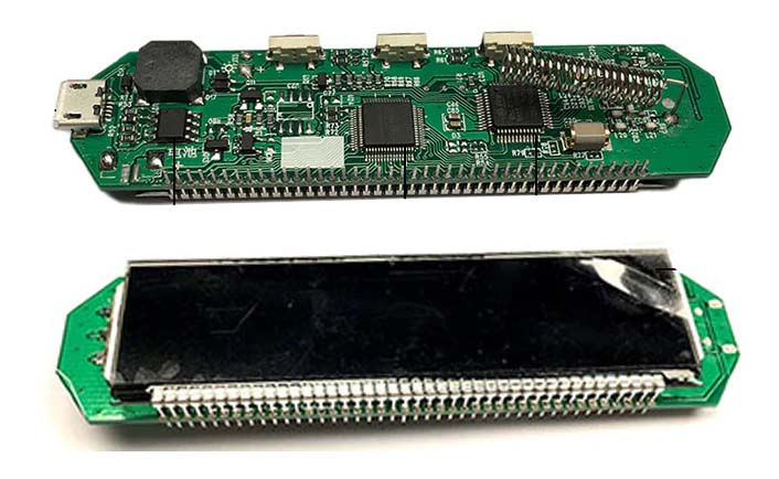
Fig. 2. TPMS system controller board
It was not possible to install the standard receiving unit just like that, since the minimum allowable pressure value is 1.1 Bar, and in a baby stroller it is less. Therefore, the module constantly beeps, informing about low tire pressure. You can read about the development of a controller for the "Smart" baby stroller "Maksimka" , in which the research results are applied, in my article [1].
Collecting information about the operation of TPMS began by searching for articles on the Internet. But, unfortunately, there is little information. And it also applies to the usually standard car systems, which are a little more complicated and much more expensive. And I needed information about a simple Chinese cheap system. I had some minimal understanding, now I had to start experimenting.
So, we arm ourselves with the USB-whistle of the DVB-tuner, launch the RTL-SDR and watch the broadcast. The sensors operate at 433.92 MHz in FSK modulation. Initially, I recorded the broadcast and then manually analyzed the protocol. Here the difficulties began. Previously, only encountered OOK modulation. Everything is simple there. It's a little more complicated here. The information is encoded with two frequencies. Therefore, I studied examples, the theory of modulations. Then I saw how the URH-Universal Radio Hacker program was used [2, 3]. I tried to install it, but it doesn't work on my WinXP 32bit. I had to look for a computer with win8 64bit and then the program was installed. You can read more about her work on the developer's website. URH made the process a little easier for me, because it captures the signal from the air, displays it with an oscillogram and immediately decodes it into a raw digital form in both binary and hex form.
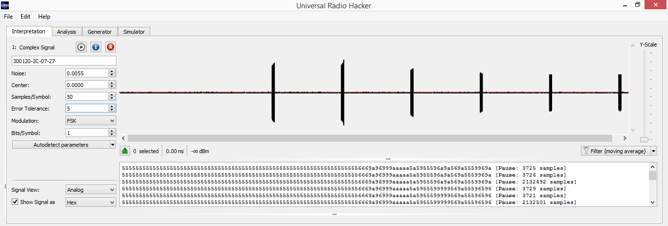
Fig. 3. Screenshot of the program with a captured frame of TPMS sending.
The sensor sends several messages one after another in one session. The period between sessions can be up to a minute or more. If an alarm situation occurs, the sensor immediately starts sending data packets. The sound file of the message from the sensor [8]. An example of one message from the sensor taken from the URH program:
010101010101010101010101010101010101010101010101010101010101010101010101010101010101010101010101010101010101010101010101010101010101010101010101010101010101010101010101010101010101010101010101010101010101010101010101010101010101010101010101010101010101010101010101010101010101011001100110100110101001011001011010011010100110101001100101010101011010010101010101010110101001011001101010010101100101101001010101011001011001100110101001In hexadecimal form, this premise will take the form:
5555555555555555555555555555555555555555555555555555555555555555555556669a965a6a6a6555a5555a966a565a556599a9It was evident that all 4 parcels in one session had the same data, which means that the packet was accepted correctly and you can start analyzing it.
In the example above, you can see the preamble (sequence 01010101….), Followed by the data. After reading the Internet, we understand that we have a package encoded with the Manchester encoding (GE Thomas). Each bit is encoded with two bits 01 or 10. I originally encoded by hand, thus reinforcing the theory of encoding / decoding. But then I decided to turn to the online decoder [4,5,6], which greatly accelerated the process.
So, decoding the original message from the sensor with the Manchester code, we get
000000000000000000000000000000000000000000000000000000000000000000000000000000000000000000000000000000000000000000000000000000000000000000010101101110010011011101110100000011000000001110010111000100110000010010101110The first 136 zeros are a preamble and can be discarded. We are only interested in data.
Translating them into hexadecimal form, we get: 0x15B937740C03971304AE
This already has beautiful initial data, in which the identifier, tire pressure and temperature are hidden somewhere.
For further research it is necessary to collect data statistics. To do this, I wound one sensor to the wheel and captured the air, while recording what the original system board shows. He released the pressure, pumped it up, put the wheel in the freezer for a negative temperature, heated it up. Then he sought the same conditions for another sensor to find out the temperature and pressure bytes.
The whole package takes 10 bytes. If you line up the received decoded data in a column, you can see constant data and changing data.
15B937740C03971304AE
15B937740C03A1FC00A4
15B937740C03A700087B
There are stickers on the sensors on the body. Each sensor is different: 0A, 1B, 2C, 3D.
The stereotypical thinking here did not work well. I thought that this is the ID-sensor.
I doubted why the ID takes only 1 byte, but then I forgot about it and tried to search for these identifiers in the stream. Then, in the menu of the original receiver of the system, I saw that other sensors could be tied to this receiver, and the receiver itself shows the sensor ID on each wheel. And, lo and behold, I found out that the fourth wheel sensor has ID = 3774.
15B937740C03971304AESo the 3rd and 4th bytes of the package are the wheel ID. Compared with other sensors and also the identifiers coincided with those displayed by the standard panel.
I counted the 1st byte as the prefix of the start of the data, and the 2nd byte as the identifier of the TPMS subsystem.
Below is the comparison of parcels from different sensors.
15B9F3FA2300BE1B007BSensor 0A ID = 0xF3FA
15B91AA43201B71B002ASensor 1B ID = 0x1AA4
15B9ABFF32027B1B029BSensor 2C ID = 0xABFF
15B937740C03971304AESensor 3D ID = 0x3774
And I realized that the inscriptions on the sensors (0A, 1B, 2C, 3D) are just wheel numbers in digital form and in alphabetic, not hexadecimal wheel id. But, nevertheless, the 6th byte in the package is very similar to the serial number of the sensor. For myself, I concluded that this is the wheel identifier. So, one more byte is decoded.
The last byte is most likely a checksum, which I don't know how to read yet. This remained a mystery to me until the very end.
The next decoded byte is the wheel temperature. Lucky here. Temperature takes 1 byte and is presented in whole degrees. Negative temperature in two's complement. This means that the temperature of -127 ... 128 degrees Celsius will fit in a byte.
In our package, the temperature is the 8th byte
15B9F3FA2300BE1B007B0x1B corresponds to +27 degrees
15B937740C03A1FC00A40xFC corresponds to -4 degrees
There are three unrecognized bytes 5th, 7th, 9th. Judging by the dynamics of the change, the tire pressure is hidden in 7 bytes, and in the 9th byte, most likely, the status bits of the sensor. According to various sources of information on the Internet, as well as the functionality of my TPMS system, there should be a bit of a discharged battery, a bit of fast pressure loss and a couple more bits that are not clear for what.
So, we will analyze the 7th byte, since we mean that the pressure is hiding in it.
Having typed statistics on different sensors with different pressures, I could not clearly define the formula that recalculates the pressure. And it is not clear in what units the sensor transmits pressure by default (Bar, PSI). As a result, the table built in Excel did not give an exact match with the standard TPMS scoreboard. One could neglect this 0.1 Bar difference, but I wanted the concept of a protocol to the last bit. Excitement prevailed.
If you cannot understand how the pressure byte is formed, then you need to make a pressure sensor emulator and, changing the pressure value, see what the standard panel displays.
It remained to find out the purpose of the 5th and 9th bytes of the packet, but they rarely change, so you can accept their values as in the original packet, changing only the pressure byte. Now the question is only in calculating the checksum. Without it, the standard panel will ignore my package and show nothing.
To emulate the sensor, you had to send a packet. For this I had a SI4432 transceiver connected to a PIC16F88, which was once used for other purposes.
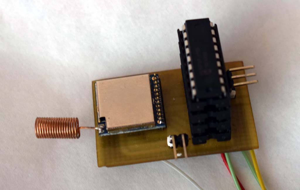
Fig. 4. Photo of the test board
Using old data transfer practices, I sketched a program for the PIC that transmits one of the packets I received with the URH program. Some time after turning on the transmitter, the panel displayed the data that was transferred to it! But this is a ready-made packet with a ready-made CRC, and in order for me to change the pressure byte, I must also recalculate the CRC.
I started reading, looking for information about which CRCs are used, tried different Xor, And and so on, but nothing worked. I already thought that nothing would work out and would have to be content with the pressure that I received according to my table, but slightly different from the original scoreboard. But on the Internet I saw an article about CRC selection. There was a program to which you give several packets, and it tries to find a checksum and, if successful, outputs the polynomial value and the CRC initialization value. [7] We
give the program several packages:
reveng -w 8 -s 15B9ABFF3202AA1B0017 15B9ABFF3202AA1B0249 15B9F3FA2300D01A00D8 15B937740C037B130089 15B937740C03BD18025E 15B9ABFF32028F150834The program issues:
width=8 poly=0x2f init=0x43 refin=false refout=false xorout=0x00 check=0x0c residue=0x00 name=(none)I wrote a program for calculating the CRC taking into account these data and ran it through the packets, what I received earlier - everything came together!
//  CRC
 crc=0x43;    //
 for(j=0;j<9;j++)
 {
  crc ^= tmp[j];
  for(i=0;i<8;i++)
   crc=crc&0x80 ? (crc<<1)^0x2F : crc<<1;  //  0x2F    CRC
 }
Hands itched to transmit pressure data. After completing the test program with a CRC calculation, I transmitted the first packet. The OEM panel received the signal and displayed the pressure and temperature. A small problem was that the standard panel had one decimal place and, while transmitting the value to the air, the screen always displayed the same pressure, because the rest of the discharges were not visible. Passed byte value 0..255. But again it is somehow not clear. It turned out that the pressure 0.00 Bar starts when the 7th byte contains the value 97. It is not clear why this is so. But then everything is clear with a resolution of 0.01 Bar.
Byte P Pressure, Bar
255 1.58
254 1.57
... ...
107 0.10
106 0.09
105 0.08
104 0.07
103 0.06
102 0.05
101 0.04
100 0.03
99 0.02
98 0.01
97 0.00
Judging by the table, the maximum pressure that fits in one byte is only 1.58 Bar, but the system allows you to measure pressure up to 4 Atm. It means that 1 bit of the most significant bit is hidden somewhere else. There was no desire to go through all the bytes and change the bits in them. A wheel from a car was found, a sensor was wound on it, a signal was captured. Curiosity prevailed, and in my mind I was betting on where this beat would appear. And that it will be exactly one bit, and not some other encoding scheme.
After decoding the packet, I saw this bit. It is the 7th bit of the 6th byte. This means that the 6th byte contains not only the wheel number, but also the most significant bit of the tire pressure.
15B937740C833C18025C
The most significant bit from 0x83 and 0x3C gives 0x13C = 219 which corresponds to a pressure of 2.19 Bar
The formula for converting pressure to Bar: P = (ADC-97) / 100,
Where ADC = (B7 >> 7) * 0x100 + B6, where B6 and B7 are the value of byte 6 and byte 7.
With a value of 511 we have a maximum pressure of 4 , 14 Bar. It was also not clear why the bar was 4.14 Bar, but I guess it is equal to 4 Atm - the maximum allowable pressure for the sensor.
It remains to understand what the status bits are responsible for. Bits were obtained by bleeding the pressure, connecting the sensor to a regulated power supply and reducing the voltage. Remained unclear 2 bits. Maybe there is more, but they have never accepted the value of one during the entire experiment.
To simplify the analysis, a program was written [8]
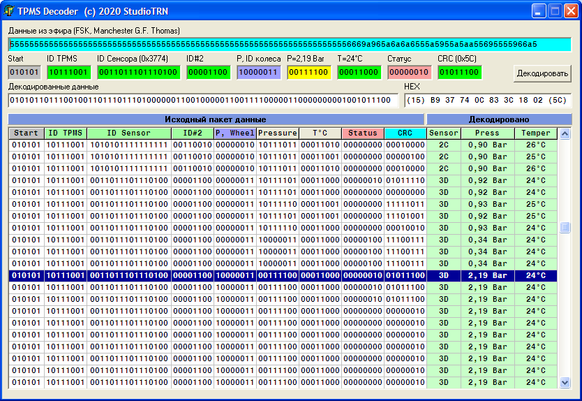
Fig.5. The appearance of the program interface for examining TPMS packages
You can set the raw packet from the URH program into the program in hexadecimal form and the program decodes the packet, reads the checksum and displays the data in normal temperature and pressure units.
Somehow I got back into the menu of the standard panel and saw that the sensor identifier is not two bytes, but four. The panel has large and small indicators and I did not immediately notice that the 2nd and 5th bytes are also included in the sensor ID.
15B937740C833C18025C
Thus, only the 1st byte remains unrecognized, but it is always 0x15 (0b010101), and this looks like a certain preamble of a packet or its beginning identifier.
Also, the status bits are not recognized exactly, but those that are missing.
Curiosity to find out what was inside the sensor took over and I disassembled one of them (Fig . 6) Fig. 6
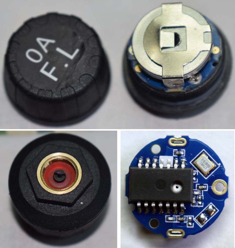
. TPMS sensor
It is based on the Infineon SP372 microcircuit with a small strapping. A search for the documentation of this particular microcircuit yielded nothing. Those that I found are either survey or advertising. So it was not possible to find out about the protocol. But the articles mention that this is a programmable controller, so the program can be anything. Therefore, I did not dare to buy the microcircuit separately.
Protocol
Now about receiving data from the sensor to the SI4432 transceiver. It was originally planned to receive raw data from SI4432 so that the controller decodes Manchester and collects bytes. But this transceiver has a packet processing function. That is, for transmission, you can configure the transmitter to the desired frequency, modulation, deviation, set the preamble length, encoding, sync word, bit rate, data length. Then write the original data packet into the transmitter buffer (for example, our 15B937740C833C18025C) and start the transmission. The transceiver itself will form a packet and broadcast it, observing all the specified parameters, while the controller is free at this time to process other information.
Ideally, I would like to receive batch data processing from the SI4432 when receiving. For the receiver to receive the packet and generate an interrupt that the packet has been received. Then the controller simply reads the receive buffer, which already stores the data in its pure form, thereby freeing up processor time for other functions.
I began to study the setting of registers for the operation of the transceiver for reception. This turned out to be much more difficult than transferring the package. Here you need to know well the theory of radio reception, which I do not have. There are tables for calculating registers in Excel for this transceiver, but they either do not work due to the fact that Excel is Russian, or they are truncated. There is also an application from the developer, but everything is not very transparent there either. After going through many examples and looking at the calculation tables, I manually read the register values according to the documentation.
I connected a logger to the output of the receiver and captured the air, depending on what the receiver gives out. As a result, I managed to configure the receiver filters so that it would let my packet through. He manipulated the flow rate, beat the tambourine. The theory, unfortunately, is still not clear to me.
In order for the receiver to be able to receive a data packet, it must specify the preamble length, the sync word that must be present, and the data length. It is also possible for the receiver to read the checksum itself, but in SI4432 the calculation algorithm does not correspond to the CRC algorithm of the pressure sensors.
The mandatory presence of a two-byte sync word could overshadow the idea of receiving a packet, but here it was lucky that the sending from the sensor starts at 0x15B9 (15B937740C833C18025C) and is the same for all sensors. This means that 0x15B9 was specified for the sync word. Data packet length is 8 bytes, checksum analysis is disabled. We set the generation of an interrupt when receiving a packet and start the reception procedure.
When the receiver receives the preamble, sync word 0x15B9 and 8 bytes of data, it will issue an interrupt to the main controller, which simply reads 8 bytes of data from the receiver's buffer. Next, the main controller will calculate the checksum, compare it and decode the received data. Fortunately, everything worked out as planned!
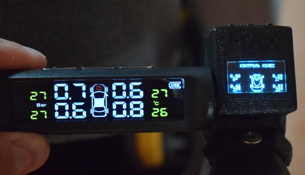
Fig. 7. Photo of the standard TPMS indicator and the display of the "smart" stroller
The following is an example of initializing the SI4432 transceiver to receive:
WriteSI4432(0x06, 0x05);	   // interrupt all disable
   WriteSI4432(0x07, 0x01);	   // to ready mode
   WriteSI4432(0x09, 0x7f);	   // cap = 12.5pf
   WriteSI4432(0x0A, 0x06);	   // uC CLK: 1 MHz

   WriteSI4432(0x73, 0x00);	   // no frequency offset
   WriteSI4432(0x74, 0x00);	   // no frequency offset
   WriteSI4432(0x75, 0x53);	   // 430-440MHz range
   WriteSI4432(0x76, 0x62);	   // 0x621A-433.924
   WriteSI4432(0x77, 0x1A);	   //
   WriteSI4432(0x79, 0x00);	   // no frequency hopping
   WriteSI4432(0x7a, 0x00);	   // no frequency hopping

   //      9090/2
   WriteSI4432(0x1C, 0x81);    // 01 IF Filter Bandwidth
   WriteSI4432(0x1D, 0x44);    // 44 AFC Loop Gearshift Override
   WriteSI4432(0x1E, 0x0A);    // 0A AFC Timing Control
   WriteSI4432(0x1F, 0x05);    // 00 Clock Recovery Gearshift Override
   WriteSI4432(0x20, 0x28);    // 64 Clock Recovery Oversampling Ratio
   WriteSI4432(0x21, 0xA0);    // 01 Clock Recovery Offset 2
   WriteSI4432(0x22, 0x18);    // 47 Clock Recovery Offset 1
   WriteSI4432(0x23, 0xD2);    // AE Clock Recovery Offset 0
   WriteSI4432(0x24, 0x08);    // 12 Clock Recovery Timing Loop Gain 1
   WriteSI4432(0x25, 0x19);    // 8F Clock Recovery Timing Loop Gain 0
   WriteSI4432(0x2A, 0x00);    // 00 AFC Limiter
   WriteSI4432(0x69, 0x60);    // 60 AGC Override 1

   WriteSI4432(0x70, 0x26);     //  Manchester,
   WriteSI4432(0x71, 0x22);	    //  FSK, FIFO
   WriteSI4432(0x72, 31);       //  31*625=19375  (     )
   WriteSI4432(0x34,10);         // 10 -    4-
   WriteSI4432(0x35,0x1A);      // preambula threshold

   WriteSI4432(0x36,0x15);      //  3  0x15
   WriteSI4432(0x37,0xB9);      //  2  0xB9

   WriteSI4432(0x27,0x2C);      // RSSI

   //
   WriteSI4432(0x33, 0x0A);     // fixpklen=1, Synchronization Word 3 and 2
   WriteSI4432(0x32, 0x00);     //
   WriteSI4432(0x30, 0x80);	    // Skip2ph, Enable Packet RX Handling=0 (   Skip2ph...)
   WriteSI4432(0x3E, 0x08);     //    8

   WriteSI4432(0x0B, 0x12);     //  GPIO0     TX
   WriteSI4432(0x0C, 0x15);     //  GPIO1     RX

   //  FIFO TX
   WriteSI4432(0x08, 0x01);// 0x01  Operating Function Control 2
   WriteSI4432(0x08, 0x00);// 0x00  Operating Function Control 2
   //  FIFO RX
   WriteSI4432(0x08, 0x02);// 0x02  Operating Function Control 2
   WriteSI4432(0x08, 0x00);// 0x00  Operating Function Control 2

   //   :  ,  ,
   WriteSI4432(0x05, 0x02);     //
   WriteSI4432(0x06, 0x00);
   //   ,       NIRQ  . 1
   SI4432_stat[0] = ReadSI4432(0x03);
   SI4432_stat[1] = ReadSI4432(0x04);
   WriteSI4432(0x07, 0x05);     //
The data reception itself will look like this:
if (si_int)		//      SI4432
   {
    //
    SI4432_stat[0] = ReadSI4432(0x03);
    SI4432_stat[1] = ReadSI4432(0x04);
    SI4432_RSSI = ReadSI4432(0x26);
    if (SI4432_stat[0]&0x02)
    {
     WriteSI4432(0x07, 0x01);      //  .     .  ,
     SI4432_ReadFIFO();            //   FIFO 8
     TPMS_Parsing();               //  CRC
     //  FIFO
     WriteSI4432(0x08, 0x02);      //  0x02  Operating Function Control 2
     WriteSI4432(0x08, 0x00);      //  0x00  Operating Function Control 2
     //WriteSI4432(0x07, 0x05);      //
    }
    else
    {
     //  FIFO TX
     WriteSI4432(0x08, 0x01);// 0x01  Operating Function Control 2
     WriteSI4432(0x08, 0x00);// 0x00  Operating Function Control 2
     //  FIFO RX
     WriteSI4432(0x08, 0x02);// 0x02  Operating Function Control 2
     WriteSI4432(0x08, 0x00);// 0x00  Operating Function Control 2
    }
    if (SI4432_stat[0]&0x80)
    {
     //  FIFO RX
     WriteSI4432(0x08, 0x02);// 0x02  Operating Function Control 2
     WriteSI4432(0x08, 0x00);// 0x00  Operating Function Control 2
    }
    WriteSI4432(0x07, 0x05);      //
    si_int=0;
   }
The SI4432_ReadFIFO () function simply reads 8 bytes from the receiver buffer, which contains the data from the sensor.
The TPMS_Parsing () function analyzes the checksum and decodes the information into final pressure and temperature units, as well as status information.
Problems
- When reading the information about the sensors, the synchronization of the sensors with each other was mentioned. For some reason it is necessary to pair the sensors, there was something about a speed of more than 20 km / h for 30 minutes. It is not clear why this is necessary. Maybe this is due to the moment of transfer of information, but this is my guess.
- Didn't find out until the end of the function of the status bits of the pressure sensor.
- It is not clear about the setting of the SI4432 transceiver for reception, about the baud rate using the Manchester encoding. It works for me, but there is no understanding of the principle yet.
Results of work
The research covered in this article took about a month of free time.
As a result of the work on the study of the protocol of the tire pressure monitoring system, the issues of transmitting and receiving data over the air were raised, the signal coding was briefly considered, the SI4432 transceiver was tested for transmission and reception. This task allowed the TPMS to be integrated into the main project of the smart baby stroller. Knowing the exchange protocol, you can connect more sensors and integrate them into your development. Moreover, the controlled pressure can be within wide limits, and not as in the standard 1.1-3.2 Bar system, because pressure outside this range is accompanied by an alarming squeak of the standard central unit system. Also, TPMS can now be used to monitor the tire pressure of a motorcycle, bicycle or, for example, an air mattress. All that remains is to physically install the sensor and write a top-level program.
Links
- "Smart" baby carriage "Maksimka"
- github.com/jopohl/urh
- habr.com/ru/company/neuronspace/blog/434634
- www.rapidtables.com/convert/number/hex-to-binary.html
- www.rapidtables.com/convert/number/binary-to-hex.html
- eleif.net/manchester.html
- hackaday.com/2019/06/27/reverse-engineering-cyclic-redundancy-codes
- My utilities, sample package, CRC selection. Archive password "tPmSutiLity" dropmefiles.com/MtS9W "
- i56578-swl.blogspot.com/2017/08/eavesdropping-wheels-close-look-at-tpms.html
- www.rtl-sdr.com/tag/tpms