This time, one article in two series.
Let's try to figure out the parachute system and test fuel combustion under pressure.

Parachute
While the turners were breaking off us, we decided to tackle the rest of the rocket systems, for example, the parachute system.
Here we decided to listen to the advice of viewers and readers and take a well-proven solution, namely the system described on the site . The fabric used for the ornithopter was taken as the material for the parachute . It's lightweight, durable and breathable - pretty good.
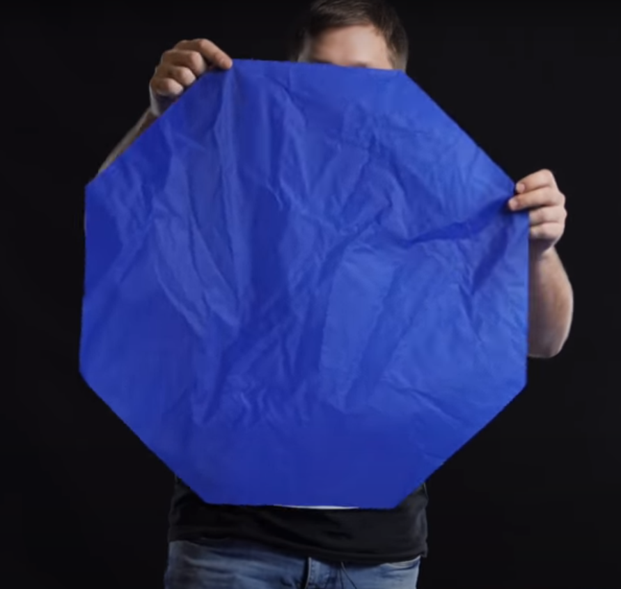
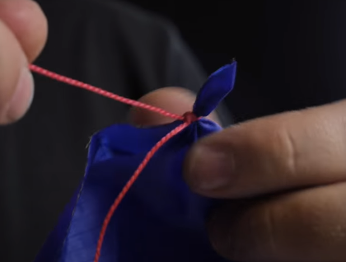
We did everything according to the instructions, tested it by throwing it out of the window.

The problem of twisting lines was discovered, which was easily solved by installing a washer with holes through which the lines were passed.
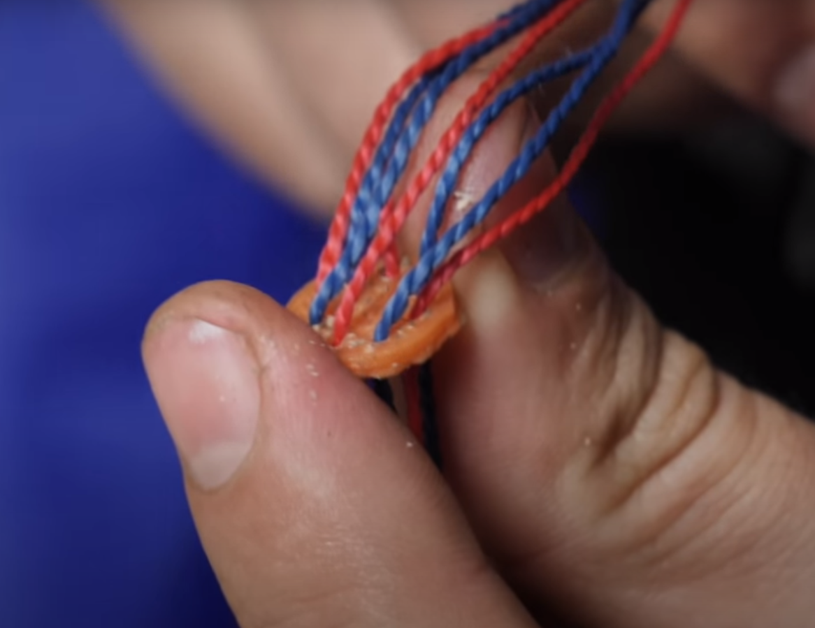
We accepted the design of the parachute and moved on to the next item.
Expelling charge
For the parachute to come out of the rocket body, it is necessary to drop the nose cone and throw the "umbrella" out of the rocket. The solution to this problem is the kick-out system. To begin with, we decided to experiment with pyrotechnic charges, because such a system is the simplest and most compact: they carefully disassembled the firecracker and poured some gunpowder (2g.) into a special cavity of the part, which, according to the idea, should separate the engine from the central part of the rocket. The ignition of the charge was left the same as was used to ignite the checkers - by supplying power to the nichrome thread.
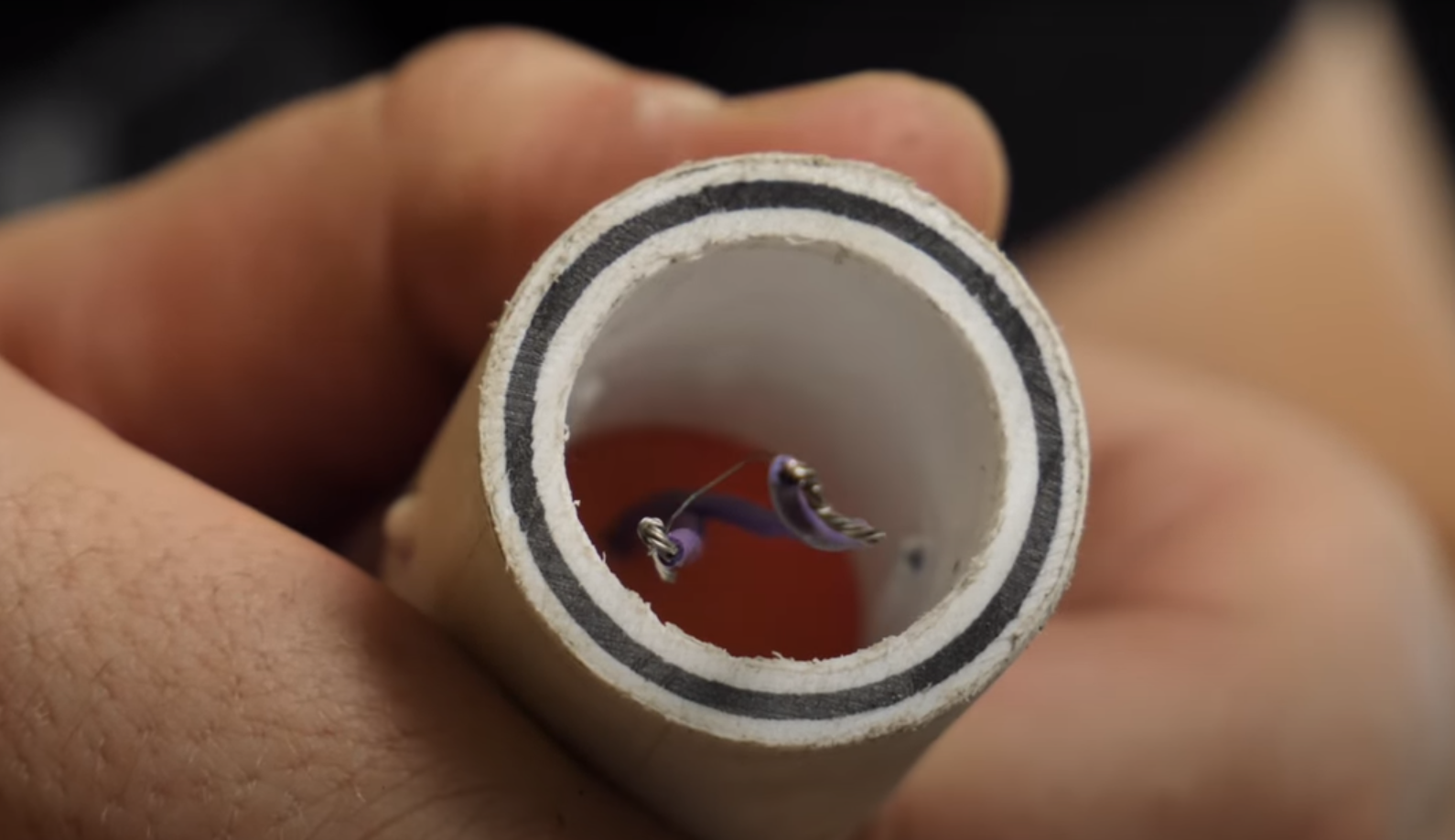
The charge was covered with a metal sponge and a piston was placed on top.

The idea is this (borrowed from the same site): when the charge is ignited, the propellant gases will pass through the fire arrester, on which the burning powder particles will settle and go out, then they will push the piston, which will eject the nose cone along with the parachute. The fairing was attached to the piston with a cable, and the piston movement was limited by screwed in screws. The body of the test model was assembled from glossy paper glued with silicate glue.
Parachute system tests
The gunpowder is loaded, the parachute is laid, a camera is inserted into the fairing and it is installed in its place in the model. For safety reasons, the dummy was mounted on a long polypropylene water pipe, which was used as a mandrel when making the body.
For testing, they chose, as usual, a deserted place, set up a stand on a tower to increase the free flight and launched.
It turned out that 2d. there is too much gunpowder for such a task - the piston, resting on the bolts, broke the body of the model. The fire arrester did not cope with its task - the nose cone and the parachute were well blown off with powder gases and somewhat melted the latter, which, most likely, led to its non-opening of the parachute.
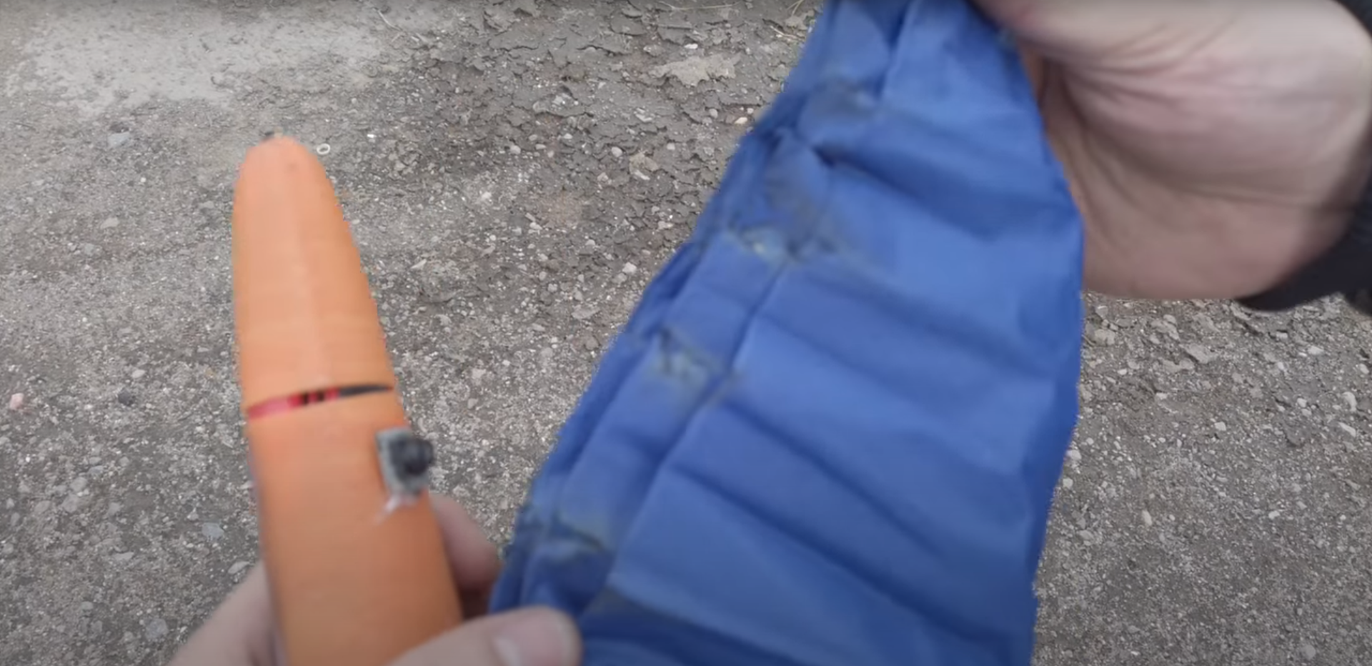
Also, we do not exclude the fact that it was not the burning powder, but the temperature of the gases. In any case, we will experiment with the knockout system.
Making a constant pressure bomb
Now that we have all the adapters, we can go back to making the Crawford bomb.
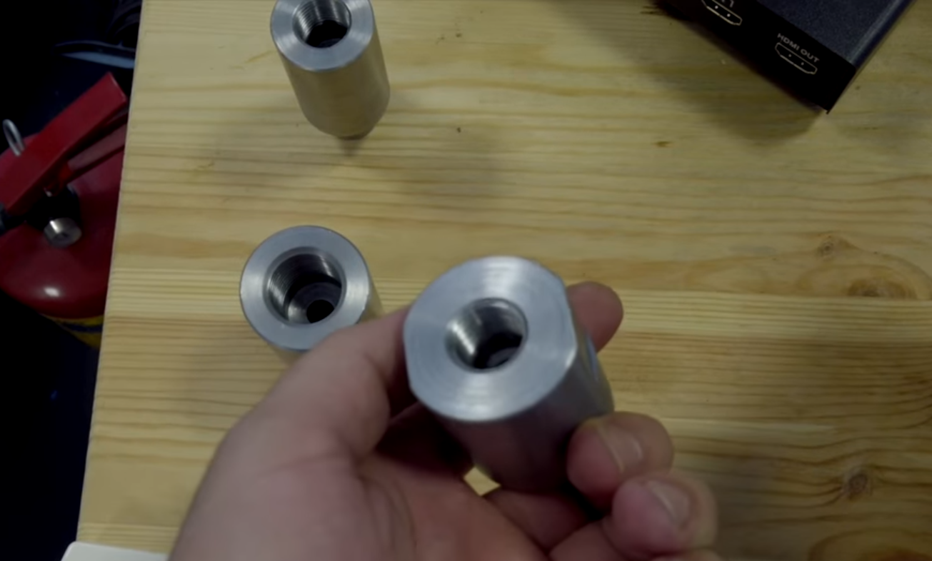
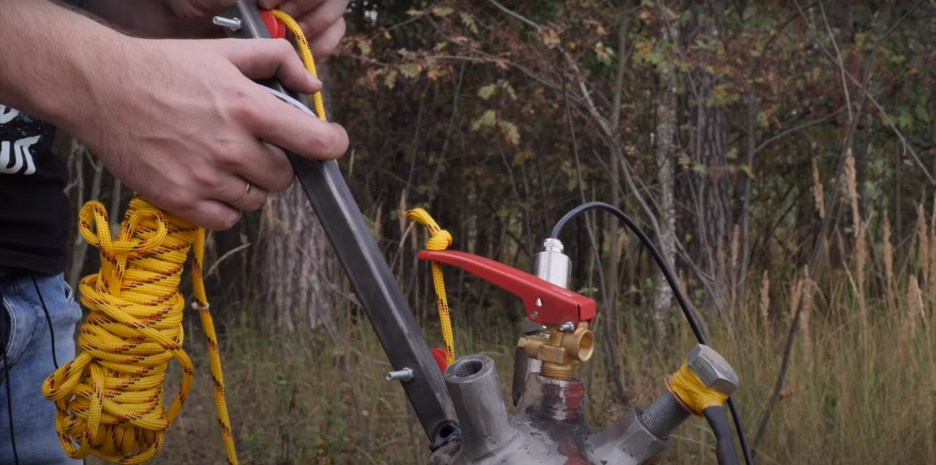
It was decided to leave the original fire extinguisher valve and use it to relieve pressure. This means that three more adapters need to be welded into the cylinder:
- for the inlet hose through which we will inject gas
- for pressure sensor installation
- to load checkers
It turned out that the fire extinguisher is surprisingly easy to drill with conventional drills. We weld the first two adapters with a tapered thread into it, for the third we use an M20 * 1.5 automobile nut. Preliminary calculations of the weld were made - with a margin, so that it turned out to be stronger than the cylinder itself.
To load fuel, we will use the bolt corresponding to the nut. We drill it along, make a branch to the side and pass 8 copper wires through it (+12 volts, ground, two signal wires for each checker and one wire for the fuse). Fill the remaining cavities with epoxy and leave until completely solidified.
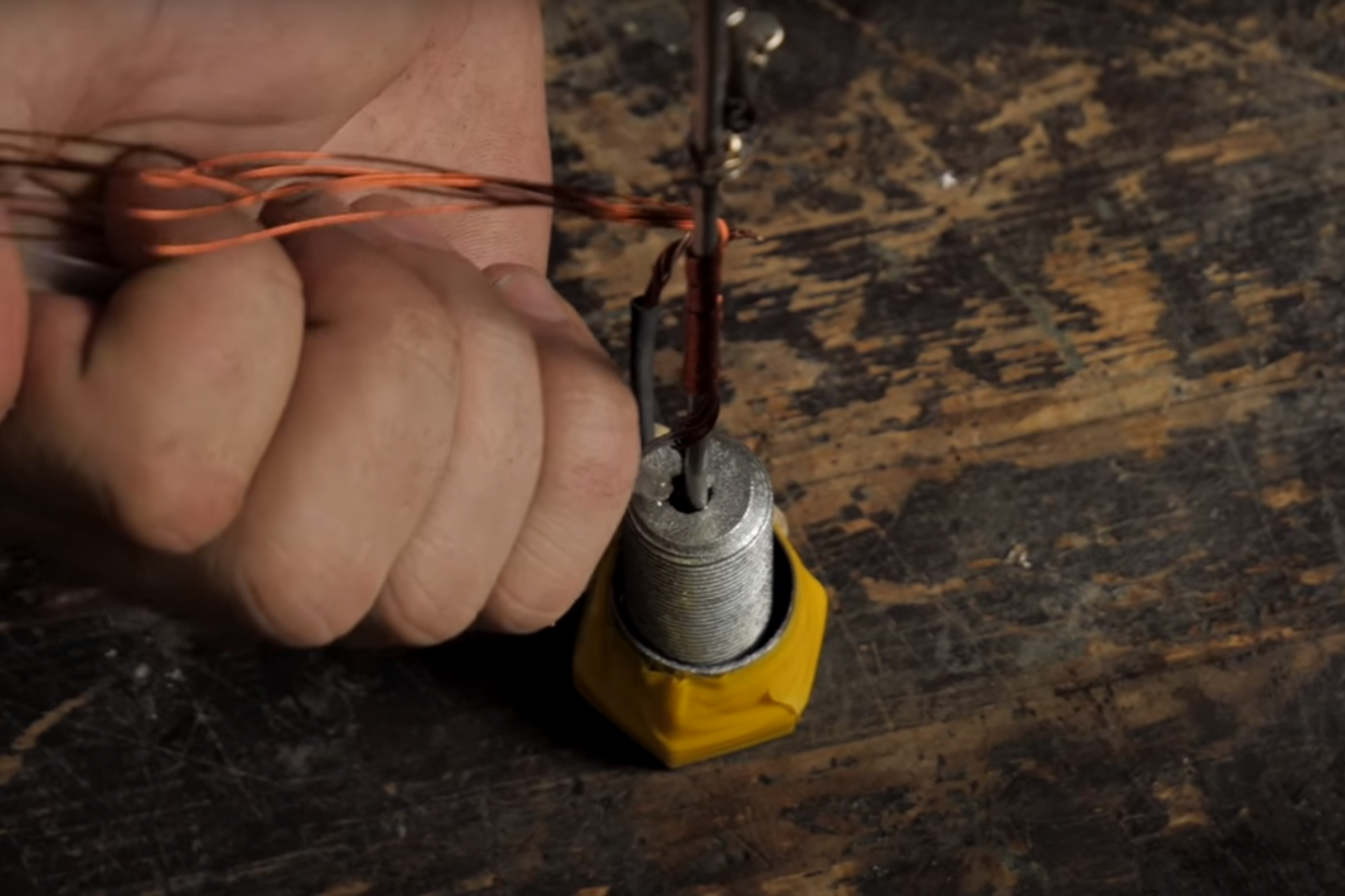
To relieve pressure safely, we tie a rope to the relief valve and pass it through two blocks fixed on an additionally welded profile.
We also improved the sketch for electronics: added a function for displaying pressure and input status in the web interface. A link to the updated sketch will be at the end of the article.
Tests
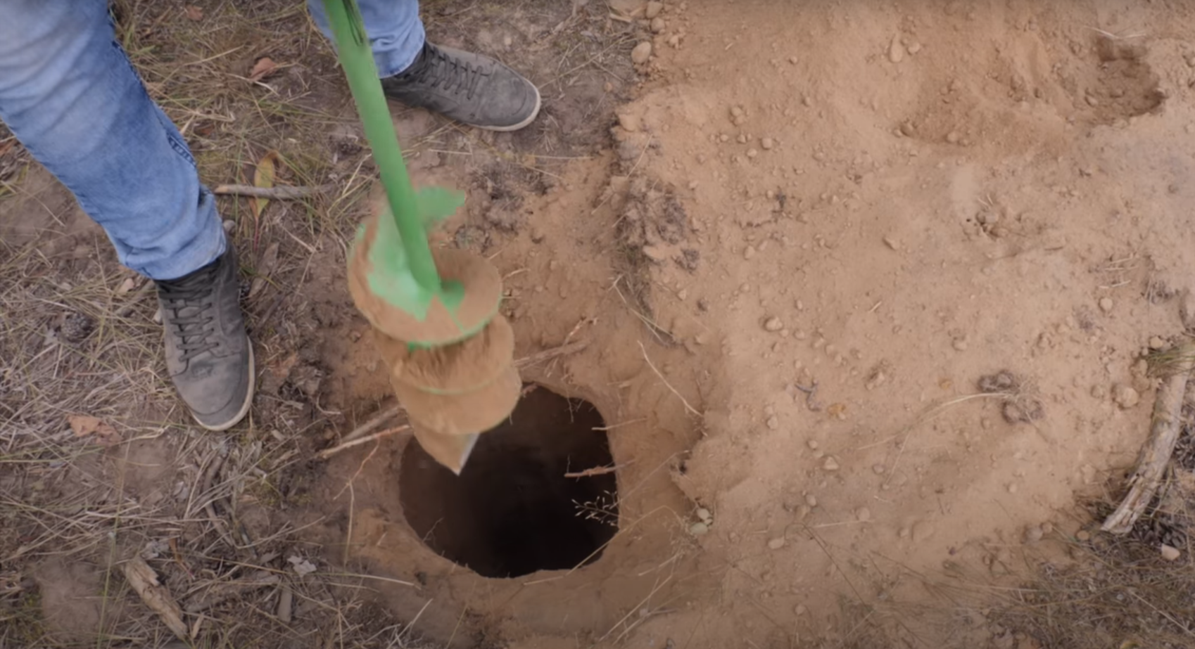
For testing, we went to a deserted place and, with the help of an ice screw, dug a hole in the ground, into which our converted fire extinguisher was submerged more than completely - safety above all.
To limit the pressure, a gas reducer was installed on the nitrogen cylinder.
On the first day, for some reason, the power switches responsible for the ignition refused to work - they had to start manually. They managed to burn only one checker - the fuse fell out of the second. I had to roll up, as it got dark - we arrived late and fiddled with preparations for a long time.
The second day was also unsuccessful. We fixed the problem with the keys, burned one checker. However, when burning the second, we again encountered a problem that befell us during atmospheric tests - a jet of heated gases burned the insulation on the wires, which led to the supply of a voltage to the logical part that was incompatible with the life of the controller.
Summary
The Crawford bomb we made normally holds pressure, but the junction of the adapter from the gearbox to the high pressure hose must be sealed.
The burning of one checker increases the pressure in the chamber by 10 bar. This is solved by bleeding off excess pressure through the relief valve.
The system for monitoring the readings and fixing the checkers must be revised. Most likely, we will use opto-isolator and other wires, plus we will make a stem from insulating materials. It is also worth considering reducing the recharge time.
Video by article:
Firmware for electronics