Miles is an Arduino Nano based spider robot that uses 4 legs for walking and maneuvering. 8 SG90 / MG90 servo motors are used as leg drives. A specially made board allows you to control and power the motors and the Arduino Nano. The board has special slots for IMU modules, Bluetooth and an infrared sensor, which gives the robot autonomy. The body is assembled from 2 mm thick plexiglass cut on a laser cutter, but it can also be printed on a 3D printer. An excellent project for enthusiasts learning about inverse kinematics in robotics.
Inspired by the mePed project (www.meped.io), and uses code based on it.


Materials
Components:
- Fee (1)
- Miles components for body assembly.
- SG90 / MG90 Servo Motors (12)
- Aduino Nano (1)
- LM7805 voltage regulator (6)
- Switch (1)
- 0.33uF electrolytic capacitor (2)
- 0.1uF electrolytic capacitor (1)
- 3.08mm 2 pin Phoenix connector (1)
- Male connectors for servomotors.
Optional:
- 2 pin connector Relimate (1)
- 10 pin connector Relimate (1)
- 4 in connector Relimate (1)
Step 1: schematic and

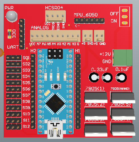

board design I design my boards in Altium . 12 SG90 / MG90 servo motors can draw up to 4-5A when running simultaneously, so the circuit must be able to handle high currents. I used 7805 voltage regulators to power the motors, however each of them can supply a maximum of 1 A. So I connected 6 LM7805s in parallel, increasing the available output current.
Download schemes and Gerber files from the link .
Features of the scheme:
- MPU6050 / 9250 are used to measure angles.
- Output current up to 6 A.
- Isolated power supply for servomotors.
- Output for ultrasonic sensor HCsr04.
- There are peripherals for Bluetooth and I2C /
- Relimate has all the analog contacts for sensors and actuators.
- Outputs from 12 servomotors.
- Indicator LED.
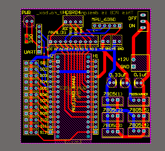
Features of the board:
- 77 × 94 mm.
- 2 layers FR4.
- 1.6 mm.
Step 2: soldering the components and loading the code

Solder components as they grow and start with surface mount devices.
In my circuit there is only one TMP resistor. Add female pins to the Arduino and LM7805 so they can be changed as needed. Solder the male pins to the motor connectors.
The circuit uses a 5V supply, separate for the motors and the Arduino. Check for a ground short on all power rails - Arduino 5V output, VCC motor output, and 12V Phoenix input.
After checking the board, you can program the Arduino. I posted the test code on Github . Fill it up and assemble the robot.
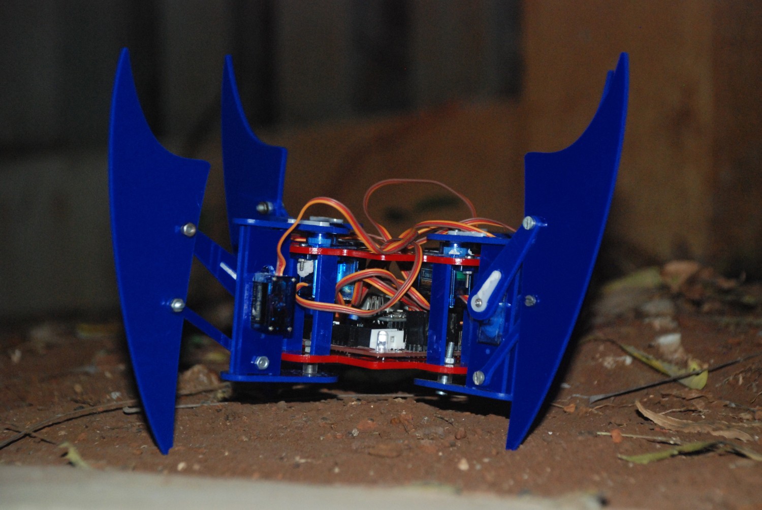
Step 3: assembling the case

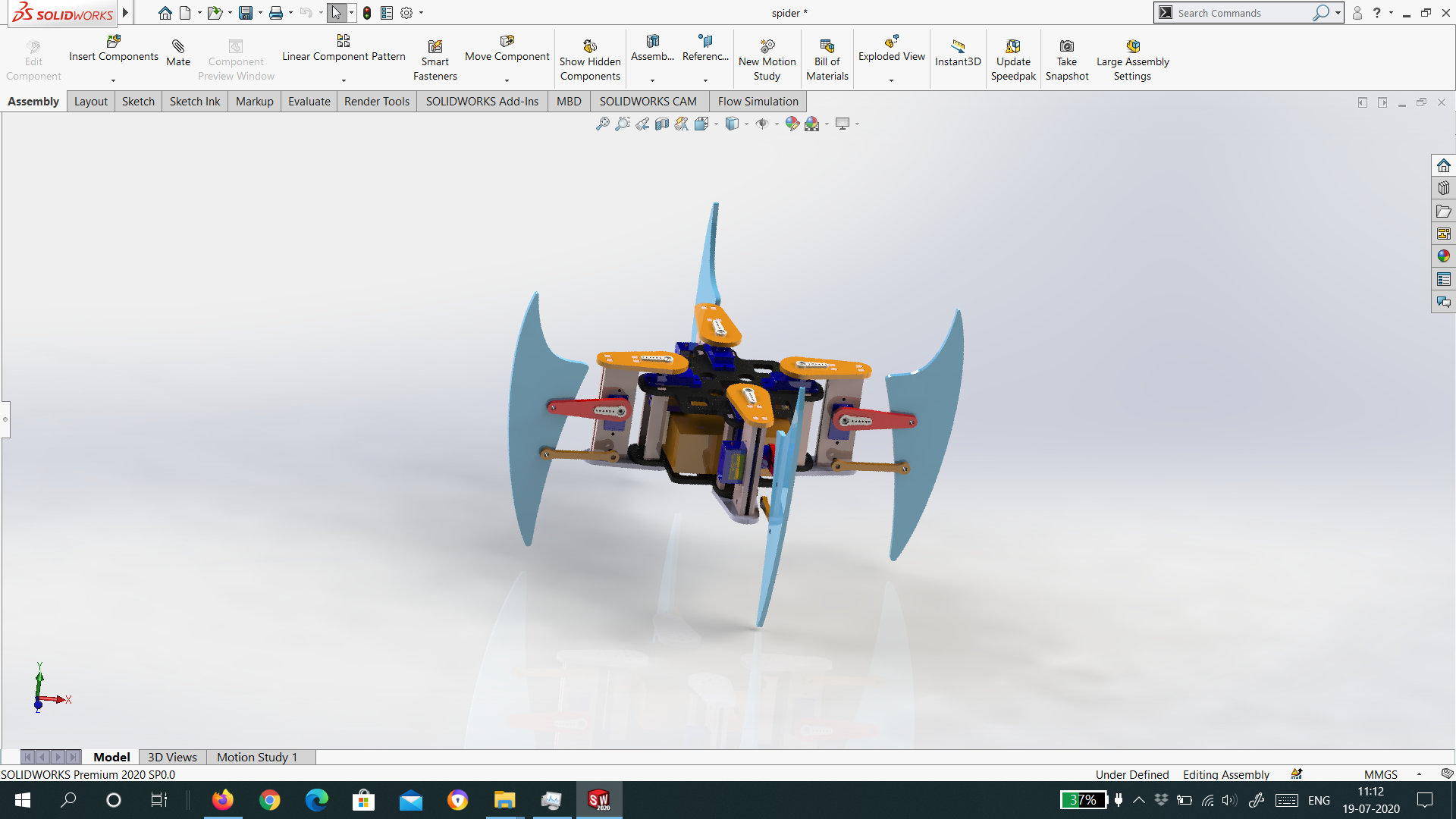
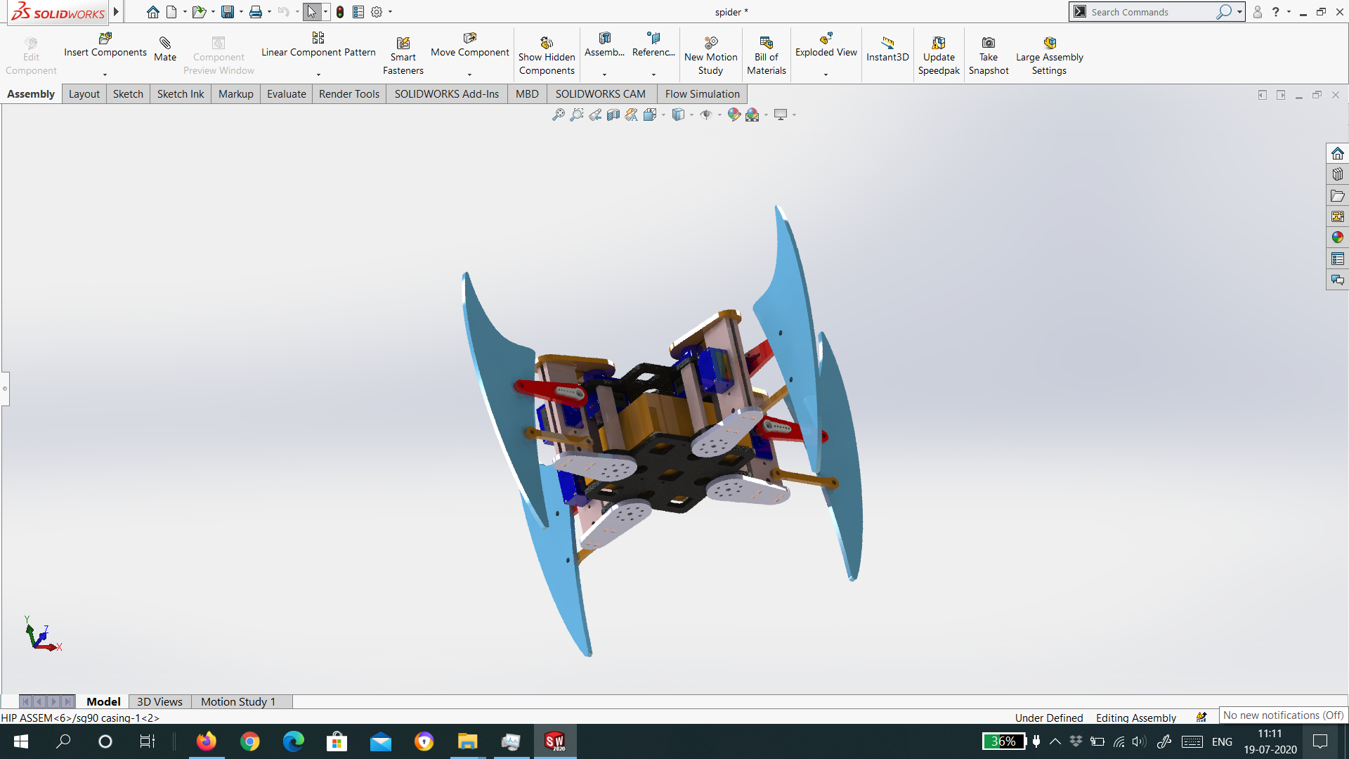
In total, the robot consists of 26 parts, which can be printed on a 3D printer or cut from 2 mm plexiglass. I used 2mm red and blue plexiglass sheets to make the robot look like Spiderman.
There are several connections in the body that can be secured using bolts and nuts M2 and M3. The servomotors are fixed with M2 bolts. Install batteries and board before screwing on the cover.
I uploaded the necessary files to Github .
Step 4: connect and test
Connect in the following order:
- Front left rotary motor.
- Front left lift motor.
- Rear left swing motor.
- Rear left lift motor.
- Rear right swivel motor.
- Rear right lift motor.
- Front right swing motor.
- Front right lift motor.
Start the robot by sliding the switch.
Step 5: future improvements
Inverse kinematics
The current code uses a positional approach - we set the angles that the motors must turn to perform a certain movement. Inverse kinematics will allow the robot to walk more sophisticated.
Bluetooth control
The UART connector on the board allows you to connect a Bluetooth module, for example, HC-05, to control the robot wirelessly from a smartphone.