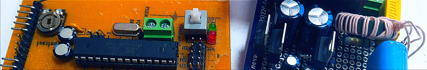
Before working on this device, I had little understanding of digital signal processing and how computer networks work at the physical level. It was necessary to quickly dive into the question and build a plan to create a working prototype.
In the process of studying, I found a lot of specialized literature on electronics, microcontrollers and digital signal processing, which helped me a lot with this. But at the very beginning of the journey, review articles like this would be useful to me to choose areas of study.
Further material is an extract from professional experience in the form in which I would like to tell it to myself from the past. Many facts have been greatly simplified for better readability.
Communication
Let's start with abstractions. Imagine that you need to transfer a piece of information from one person to another. In the image: the red man is the transmitter, and the blue is the receiver.
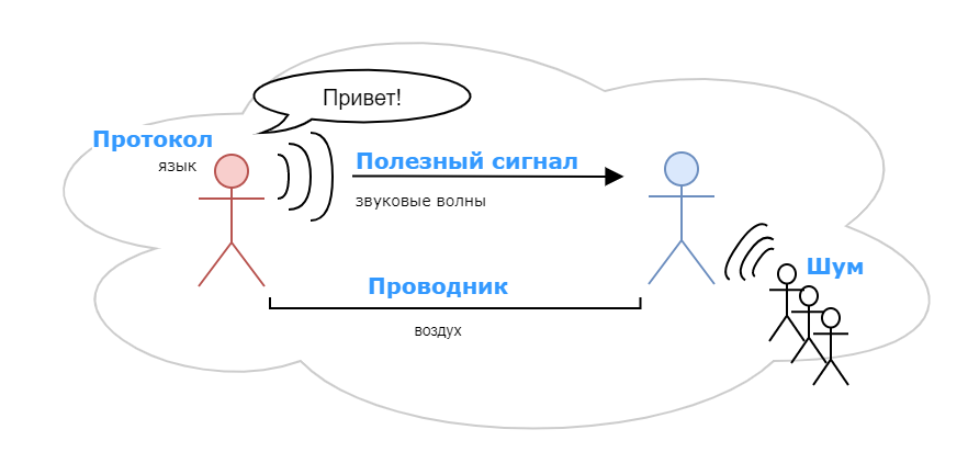
We will use voice to transmit information. Information is some kind of text in our head. The text can be divided into letters and each letter can be represented as a sound signal. In this way, each letter can be encoded with some appropriate sound signal.

Conductor
Sound, as you know, propagates in the form of waves - fluctuations in the density of air or other medium. In our case, the medium for signal propagation is air. From the red man, sound waves spread through the air in all directions.
Useful signal

Fortunately, we cannot mentally transmit information from our head directly to the head of the interlocutor. Therefore, the letters from our head at the “hardware level” we transform (encode) into sound signals (sets of sound waves). We will call this a “useful signal”.
Important: each letter is encoded by a stable set of sound waves. From these waves we can recognize a certain letter (if we know it, of course). There is a conversion from letter to sound and back from sound to letter.
Noise

Noise is the same signal, but it does not carry useful information. Noise distorts the desired signal and reduces the range of reliable reception. It can be a crowd of people loudly talking about something of their own, or maybe even an echo or other extraneous sounds that are mixed with a useful signal. Noise usually interferes with the passage of the wanted signal to the receiver.
Protocol

In this form, the signal reaches the receiver. The receiver recognizes (decodes) letters from a set of sound waves and collects words from them. If it seems to him that this is a meaningless set of sounds, then he discards them or tries to restore the original signal using a complex algorithm. Partly, because of this, we sometimes first ask “What?”, And only then we realize that we have heard everything.
A protocol is, in fact, a set of rules and algorithms by which we can extract information from a useful signal. In this example, this is our language in which we communicate with the interlocutor. From it we learn the meaning of the transmitted sounds. All this happens unconsciously, we can say “at the hardware level”.
Everything described above in a very simplified form shows how data transfer works not only between people, but also between electronic devices. They will only have a physical effect, for example, an electric voltage, and a copper cable as a conductor. The information stored in the device can be transmitted using various physical transmission media and protocols, but the essence is approximately the same: conductor, physical impact, protocol.
Power lines as a communication channel

Next, we will figure out step by step how to transfer data over power lines, and along the way, we will come up with a protocol for our
To use power lines as a communication channel, you need to understand how they work, and what physical processes occur in them.
Let's take a look at the scheme for delivering electricity from a substation to residential buildings. The electrical networks are three-phase, and there are three “phases” (A, B and C) from the substation, which are electrically isolated from each other.

For simplicity, let's agree that each phase is a separate communication channel. Devices connected to different phases cannot hear each other.
Now there are devices on the market that can communicate between phases, for them the entire substation is one communication channel. But so far this does not play a special role for understanding.
Further, in the diagrams, we will consider only phase "A" (in others, everything is similar).

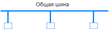
When several transceivers are connected to one phase, a network topology of the “common bus” type is formed. A signal sent by one of the devices will be received by all other devices within the signal propagation range.
Conductor
Let's study the signal transmission medium in more detail. To do this, consider the form in which electrical energy is transmitted, and find out how through this flow we can transmit our useful signal.
Electricity is transmitted in the form of alternating current. The conductors are usually aluminum or copper cables. The voltage in the electrical network has the form of a sinusoid with a period of 20 milliseconds (frequency 50 Hz).

Since the current is alternating, it periodically changes the direction of the "flow", and at the time of the change in direction, power is practically not transmitted (if you do not take into account the shift due to a strong capacitive or inductive load). There are moments of calm. This is called "zero cross" (hereinafter ZC ) - the moment at which the voltage is zero.

At this point, the network also has the lowest noise level. This is the most favorable moment for generating a useful signal.
In an electrical network with a frequency of 50 Hz (as in Russia), the ZC moment occurs 100 times per second. And if you transmit one character at a time through one zero crossing, then the connection speed will be 100 baud. The transmission rate in bytes already depends on the frame format, on how many service bits, in addition to the data itself, will be in the frame (about the frame format below in the text).
Synchronization
Another important point is the synchronization of the moment of transmission and reception between devices.
For our new protocol we will use “synchronous data transfer” as it is easier to implement.
The transmitter needs to know at what specific moment the DAC needs to be turned on to generate the signal. The receiver needs to understand at what specific moment it is necessary to turn on the ADC to measure and digitize the incoming signal. To do this, someone has to signal the processor.
This will be done by a separate part of the Zero Cross Detector circuitry. He just waits for the line voltage to be 0 volts, and gives a signal about it. In networks with a frequency of 50 Hz, the signal will arrive every 10 milliseconds.

Electric voltage propagates at the speed of light, and therefore we can conditionally assume that the moment ZC occurs at all points of the network simultaneously.
On the Internet you can find examples of detector circuits called "Zero Cross Detector" or "Zero Cross Detector".
Useful signal
There are various options for coding information for transmission over power lines . We will use narrowband frequency-shift keying because it is easier to understand and more reliable. The downside is the low data transfer rate, but for us this does not play a special role yet.
The wanted signal is an ordinary sine wave of fixed amplitude. Only the frequency of the signal changes. Let's pick a pair of frequencies and say that a signal with one frequency is “0” and a signal with a different frequency is “1”.

Alternatively, as in the "X10" standard, the presence of a signal means "1", and its absence means "0".
Note. The frequencies of the useful signal are of the order of 35-91 kHz. All the lower signal component (50 Hz and harmonics) is cut off at the input to the device. All that remains is the high frequency noise mixed with the useful signal.
Physically, this signal can be generated using a DAC module , which is found in almost any modern microcontroller. At the input, the DAC takes the numbers (signal level) by software, and outputs the voltage level corresponding to this figure at the output. In such a simple way, you can supply an array of numbers to the DAC module by timer , and at the output you can get a sinusoid with the frequency we need.

More on how to efficiently generate a sine waveform in the next article.
Noise
A rather powerful signal is initially present in the power transmission line - this is the transmitted electrical energy from the substation to residential buildings. And under load, there is a lot of noise over a wide bandwidth. Household appliances, computer power supply, chargers - they emit a wide range of frequencies into the electrical network.
For understanding, let's compare a dedicated data line with a power transmission line .
A dedicated line is a separate wire through which a number of devices communicate. It can be compared to an empty room in which you can comfortably communicate.
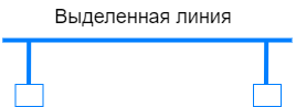
A power transmission line can be compared to a corridor in which work is carried out with a perforator, and a train is traveling in the middle (very noisy). In these conditions, it is difficult to convey information, but it is real.

Protocol
The coding is very simple - we select several symbols and assign a certain signal frequency to each one. Let's make three symbols for simplicity:
- “Start” - by this symbol the device will understand that frame transmission has started;
- “0” is the character for bit 0;
- “1” is the character for bit 1.

Based on the signal from the ZC detector, the transmitter generates a sinusoid of the desired frequency for a short time. And thus, one character ("S", "0" or "1") is transmitted for one transition of the mains voltage through zero (every 10 milliseconds). Receivers measure this signal, find out its frequency and write the symbol corresponding to this frequency ("S", "0" or "1") in the buffer.

Now we are able to report the beginning of the frame and transmit a set of ones and zeros. Further, we will add words or "frames" from them. Integral portions of information.
Frame format
We also need to come up with a frame format that we will transmit using these symbols. There are several important points that will affect the data format: frame length, addressing, integrity check.
Frame length
The larger the data portion, the lower the data transfer overhead, since in addition to the data itself, the frame contains overhead information such as a checksum and destination address. But the smaller the piece of data, the more likely a successful transfer is. It is important to find a middle ground here. This is usually determined empirically. To take an example from computer networks, the Ethernet frame was limited to 1500 bytes of data (despite the fact that this figure is quickly outdated, it is still used today).

With a strong increase in the frame length, the probability of transmitting at least some data tends to zero.
Addressing
We must not forget that we have a "common bus" network topology. All devices will receive information sent to this bus. And in order for their communication to somehow work out, they must have addresses.
We will add the address to the very beginning of the frame so that the receiving side, for which this data is not intended, does not waste time listening and waiting for the entire frame, so we will free the processor a little from useless work.

The address length is selected based on the maximum number of devices that can be simultaneously in the same scope. For example, 8 bits is a maximum of 255 devices (if you leave 0 as broadcast).
Integrity check
When transmitting information over power lines, there is a very high probability of losing part of the data. Therefore, there must be an integrity check. For these purposes, a "limit switch" is added to the frame. This is some redundant information with which the receiver will be able to make sure that the data is not corrupted.
Let's come up with the final look. Let the address length be 8 bits (255 devices on the channel + 1 broadcast address). Then comes the data 8 bits (1 byte).
We will have a trailer just the result of adding an address and a byte. But there is one caveat: the device can stably catch strong noise at the frequency of our symbols "0" or "1" and think that this is a useful signal. And there is a high probability of false readings of extreme values like "0x00" or "0xFF". To protect against this, when calculating the limit switch, we will simply add the number "42".
Something like this will look like one data frame: we send the number "110" to the device with the address "17", the limit switch "169" (110 + 17 + 42).

The whole frame will be assembled piece by piece from the incoming symbols "0" and "1" after the symbol "Start".
Let's describe the algorithm for receiving a frame.
Initially, the device is waiting for the "Start" symbol. The buffer is disabled, we do not write anything to it.
When the "Start" symbol comes, for convenience we clear the receive buffer and start the bit counter (we will determine the whole frame by the bit counter).

Each next character ("0" or "1") is sequentially written to the receive buffer and the bit counter is incremented.

When the required number of bits is collected (full frame), we check the integrity. Select from the frame "Address" and "Data". We count it using the "Limit" algorithm and compare it with what is in the frame.

If the values agree, we extract the data from the frame and send it to the higher protocol.

If the values do not agree, we continue to wait for the "Start" symbol. And all over again.
This is how we can slowly but surely transfer byte by byte from one device to another. The receiver will add these bytes to the receive buffer of the protocol at a level higher than the physical one, and there it will already decide what to do: execute the incoming command or return some data in response.
Outcome
In this article, I tried to introduce the reader to the topic of data transmission over power lines in a general and understandable language. I hope someone will find this information useful, perhaps not only in the field of PLC .
In the next part I would like to talk about the fast sine generation algorithm that I used. And how to find out its frequency ( DFT ) from the array of numbers of the digitized signal . I'll tell you a little about the glands for all this.
Perhaps someone in the comments will throw more ideas. I would be glad to receive feedback!
Links and materials on the topic:
- About network noise
- More about network noise
- One of the variants of the "Zero detector"
- Wiki: Power Line Communication
- Wiki: Three Phase Power System
- 51317.3.8-99 ( 61000-3-8-97) . .