He took out the board, soldered the conductors to an impromptu stand and tried to reverse the circuit. Unfortunately, I can solder and mount the elements much better than I understand the processes taking place in the circuit. I think experienced electronics engineers will not refuse courtesy and explain the principle of work.
There are three parts on the board: a three-legged one with the inscription E16D2 (I think this is a bipolar transistor), a ceramic capacitor and a dumbbell choke with a "100" print.


Soldered some conductors by mistake in the same places, but that's okay. Let's take a look at the oscillograms at the control points:
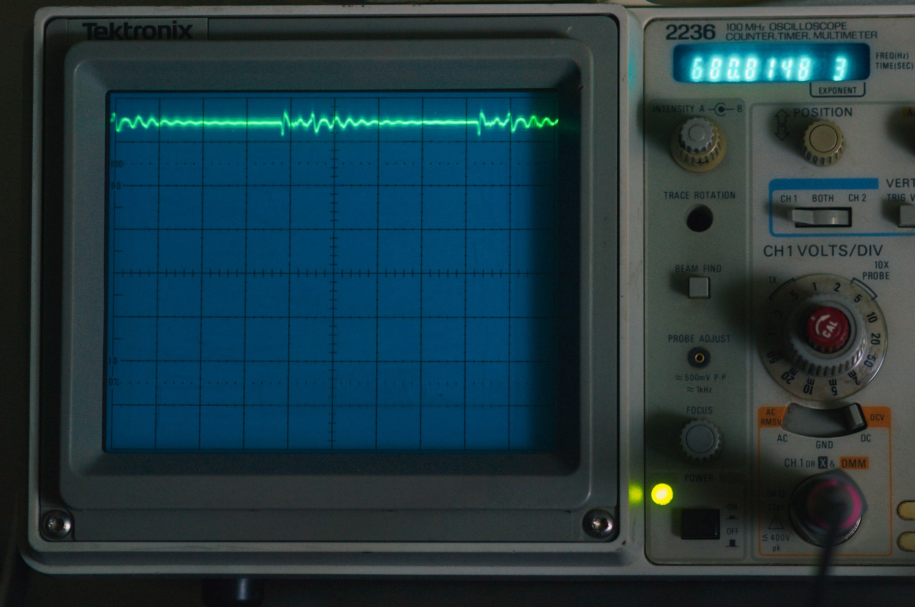
Earth. One division = 0.5 V

Point number 1, VCC. The instrument displays the frequency captured by the 685 kHz trigger.

Dot number 2.

Dot number 3. 2.7 volts per LED, expected.

This is how the circuit behaves in dynamics, the graphs show some complex oscillations and resonances about the reasons for which I can only guess.
I would be glad if someone explained what was going on. In general terms, the essence is clear, this is a primitive DC-DC booster, but how exactly it works is not clear. How is the transistor turned on and is it a transistor at all?
Thanks!