My homemade
Before making my keyboard, I set the following goals:
- Highest possible tactile comfort.
- , , , . .
- — , . . RGB – , . .
- . .
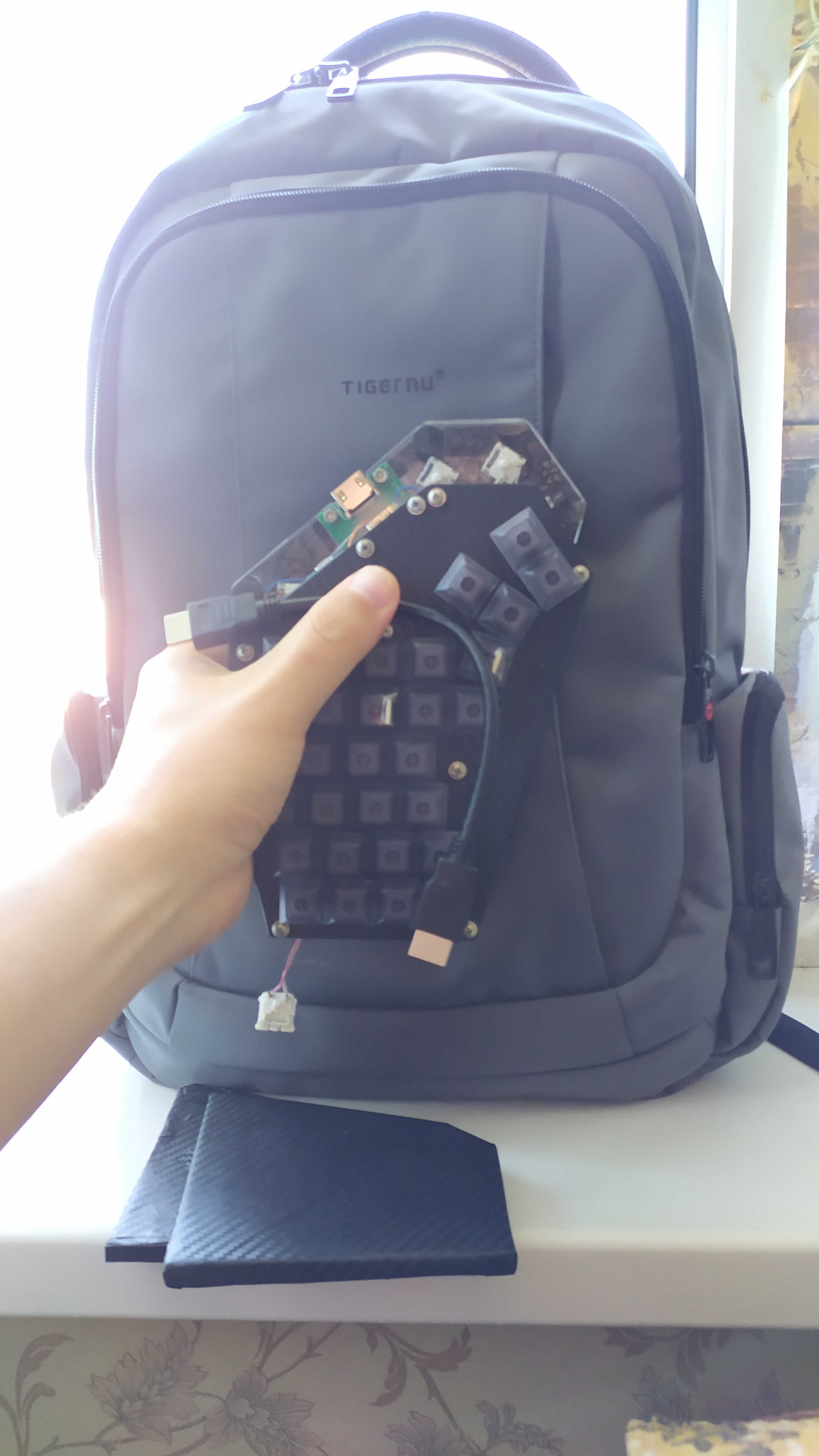
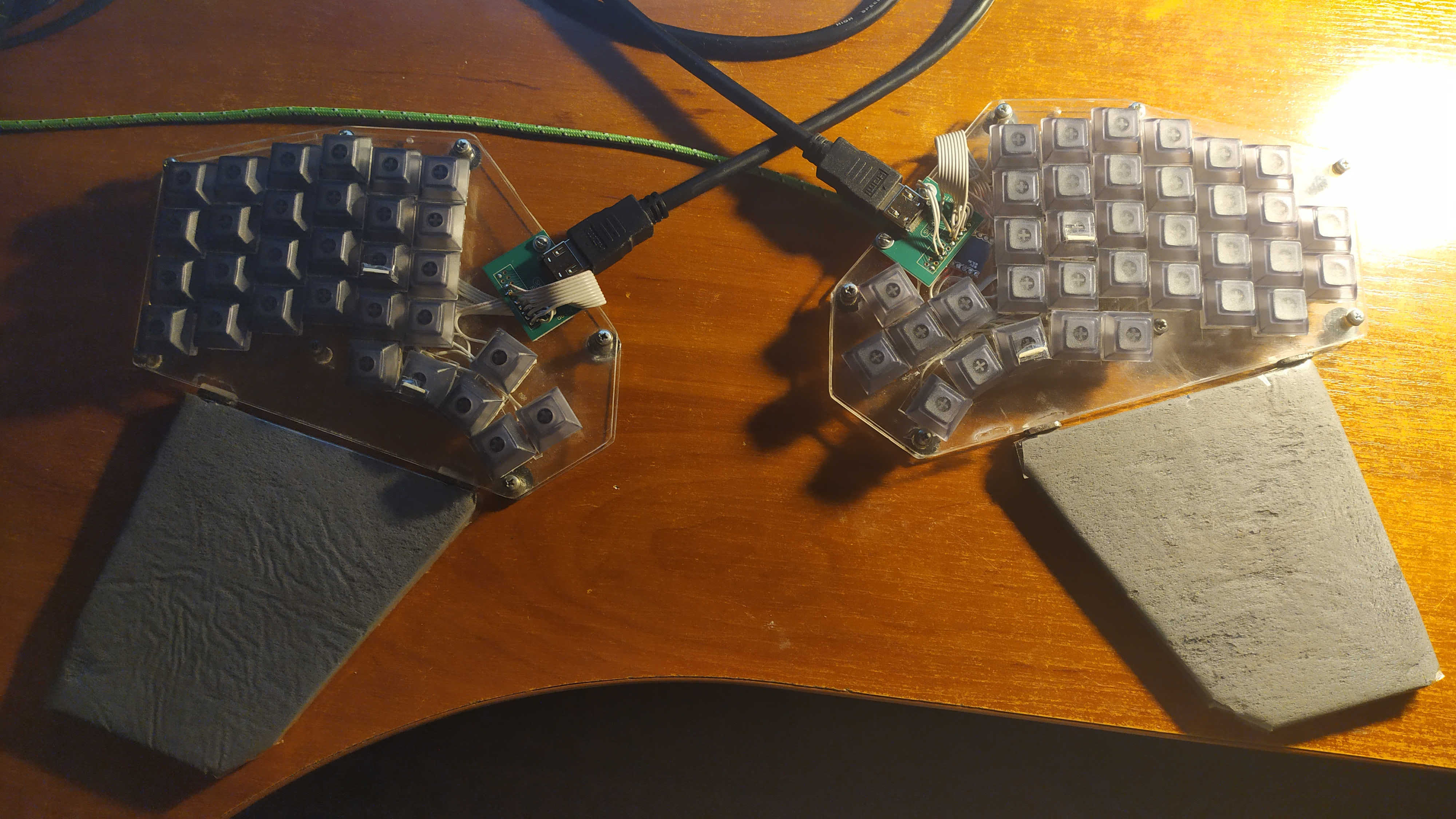
Did I manage to achieve this? Look, it fits into my backpack without any problems:
Warning - 90 compressed pictures: I tried to write an article as “chewed up” as possible - understandable to the widest possible circle of people, including those who are not technically savvy and who do not understand programming at all. Therefore, I apologize in advance if someone gets the impression that the article has a lot of water or too many pictures.
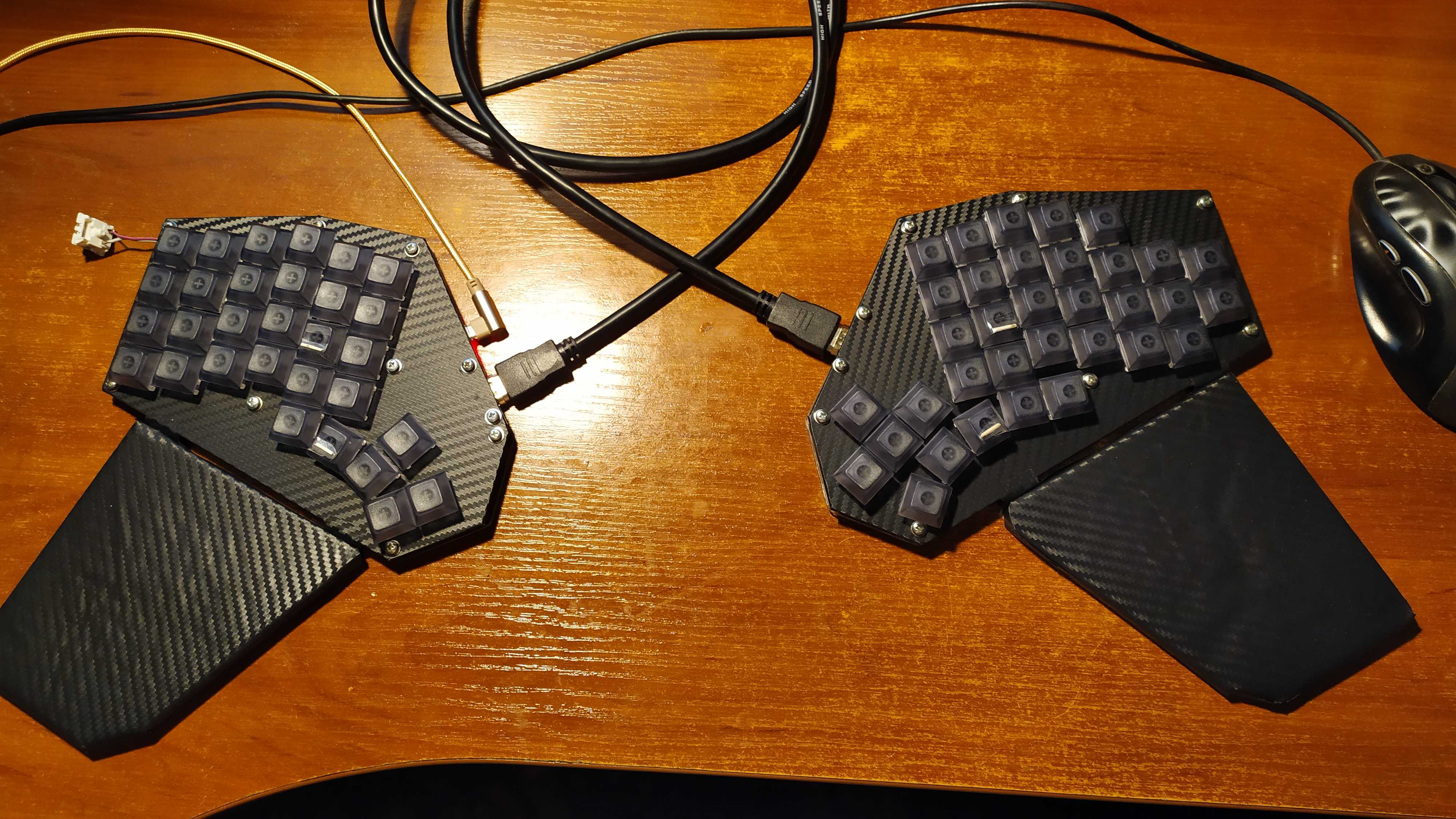
Keyboard with a short HDMI cable:
Let's learn terms for understanding further text. Below in the photo is a button, switch, switch. Switch - Englishism, a borrowed word from a foreign language.

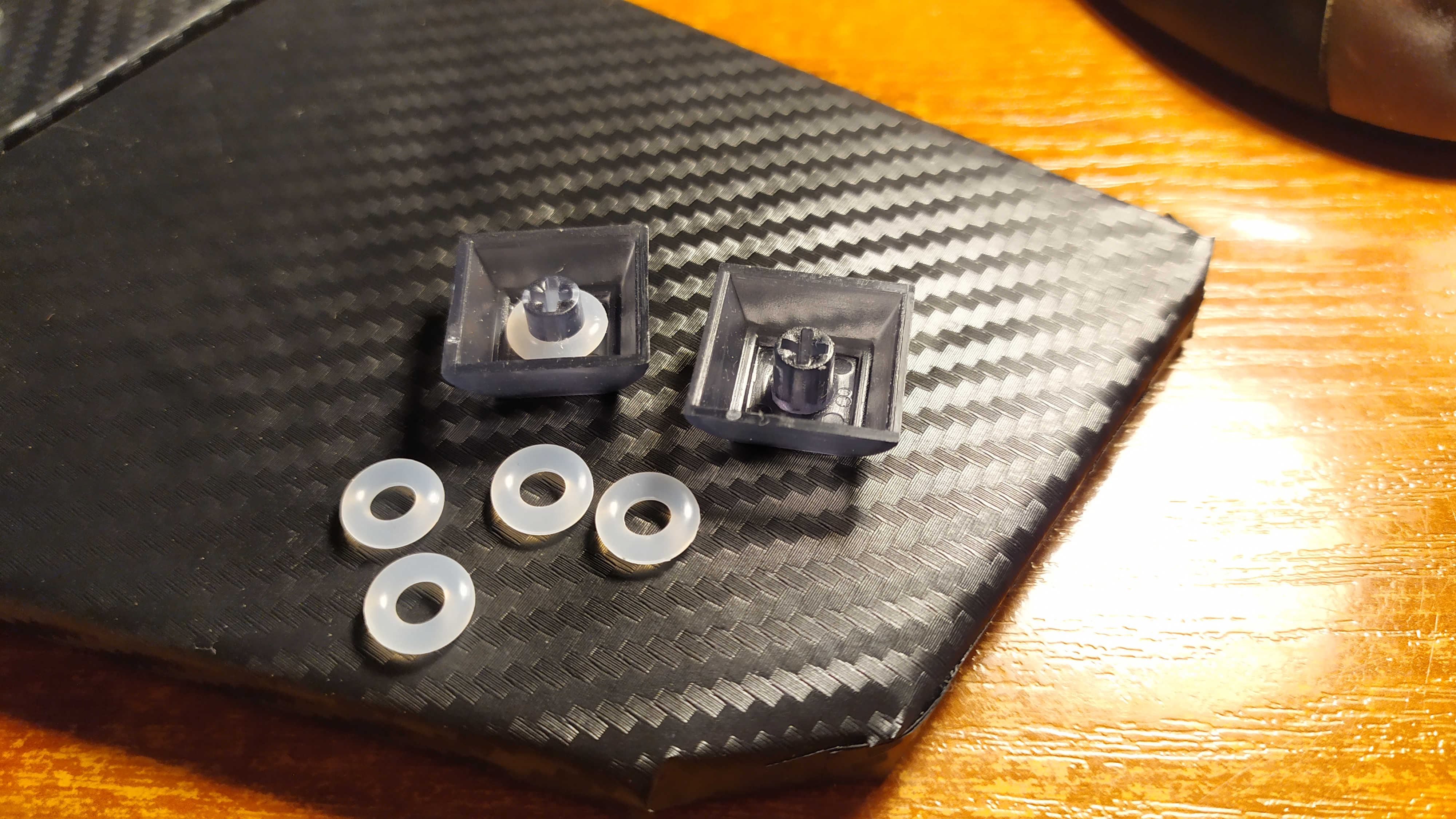
In the photo below - a cap (keycap) and rubber rings for them:
Who needs a historical digression and why I chose this particular keyboard shape, take a look here:
The agony of choosing a layout
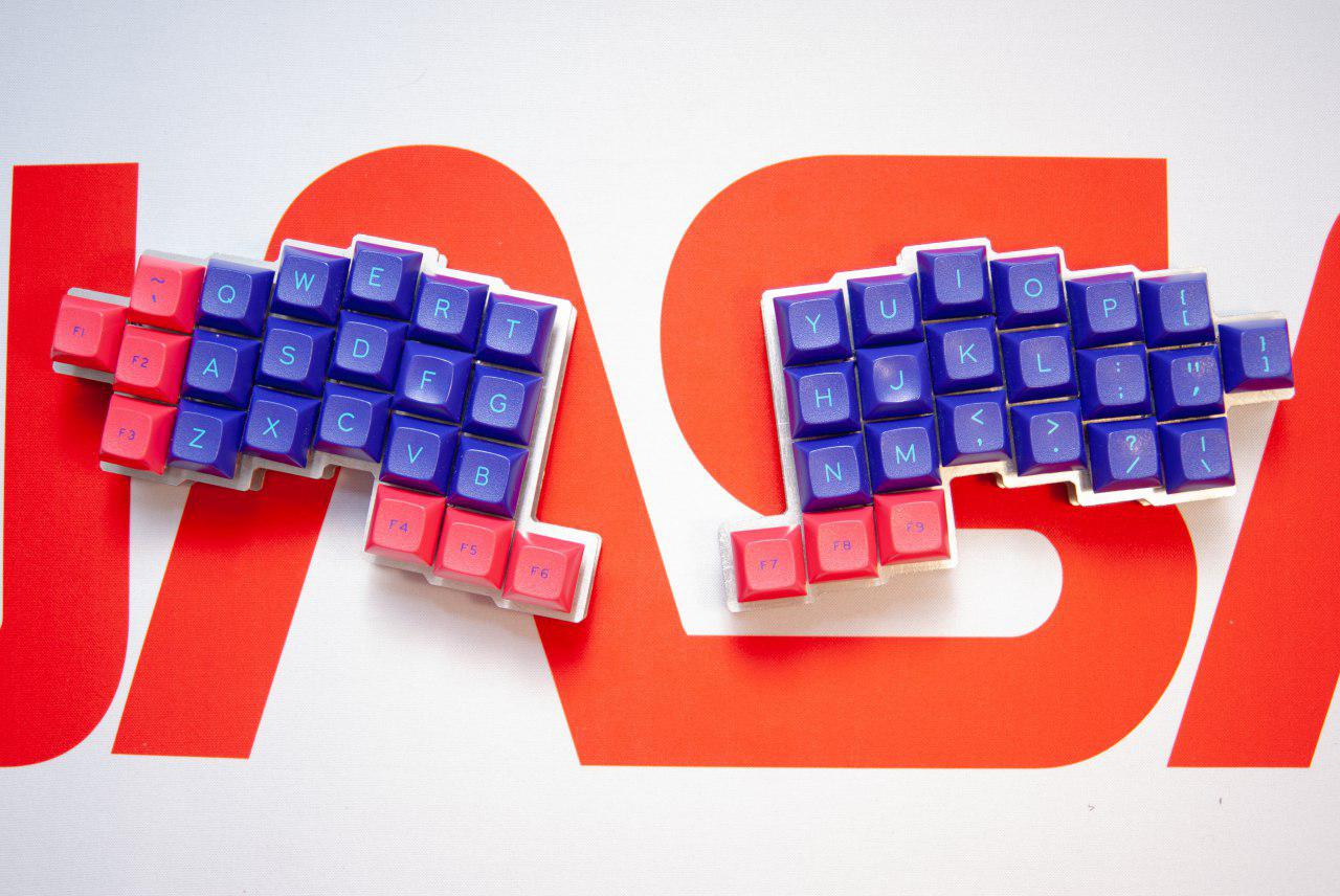
So let's go. We want to make a split keyboard, google "Iris keyboard", it looks something like this:
One could buy one, but there are no "X" and "b" buttons on it, and I have no desire to retrain to their new arrangement. So the keyboard is not bad, but it doesn't suit us. Our compatriot came up with a convenient option - "jian keyboard", look:
But it is not convenient either, the result is a concept that is suitable only for working in text editors. In my opinion, he overdid it here, eliminating the top row of number keys. There is a modified version - "jiran keyboard":
It will be more comfortable to work for this, in contrast to the previous one. When working in Word, the cursor keys, F1-F12, the "Delete, PgDown, etc." it is quite comfortable to press the Fn key. The right hand has much less to reach for the mouse - this is a huge plus, which you begin to understand only by feeling it. On this basis, you can start developing your own version. My first prototype looked like this:
I can tell right away that five thumb keys are a lot. The finger hardly reaches the fourth button, and the fifth has to be reached. I was the one who was greedy then. And, looking ahead, I will say that there were very few cursor keys. In the current layout, I have 4 buttons under my thumbs, located in an arc. It's convenient for me:
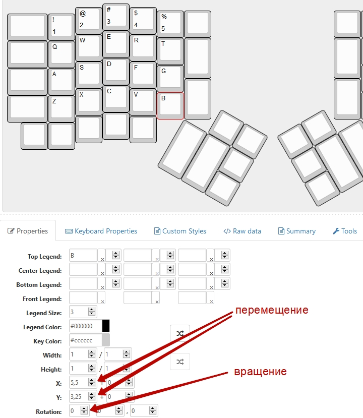
Follow the link: keyboard-layout-editorand select Ergodox in the Presets tab. Buttons can be removed, added, rotated and moved as you see fit. Practice it, there is nothing difficult there.
When you get comfortable, follow this link to my project: ErgoRU
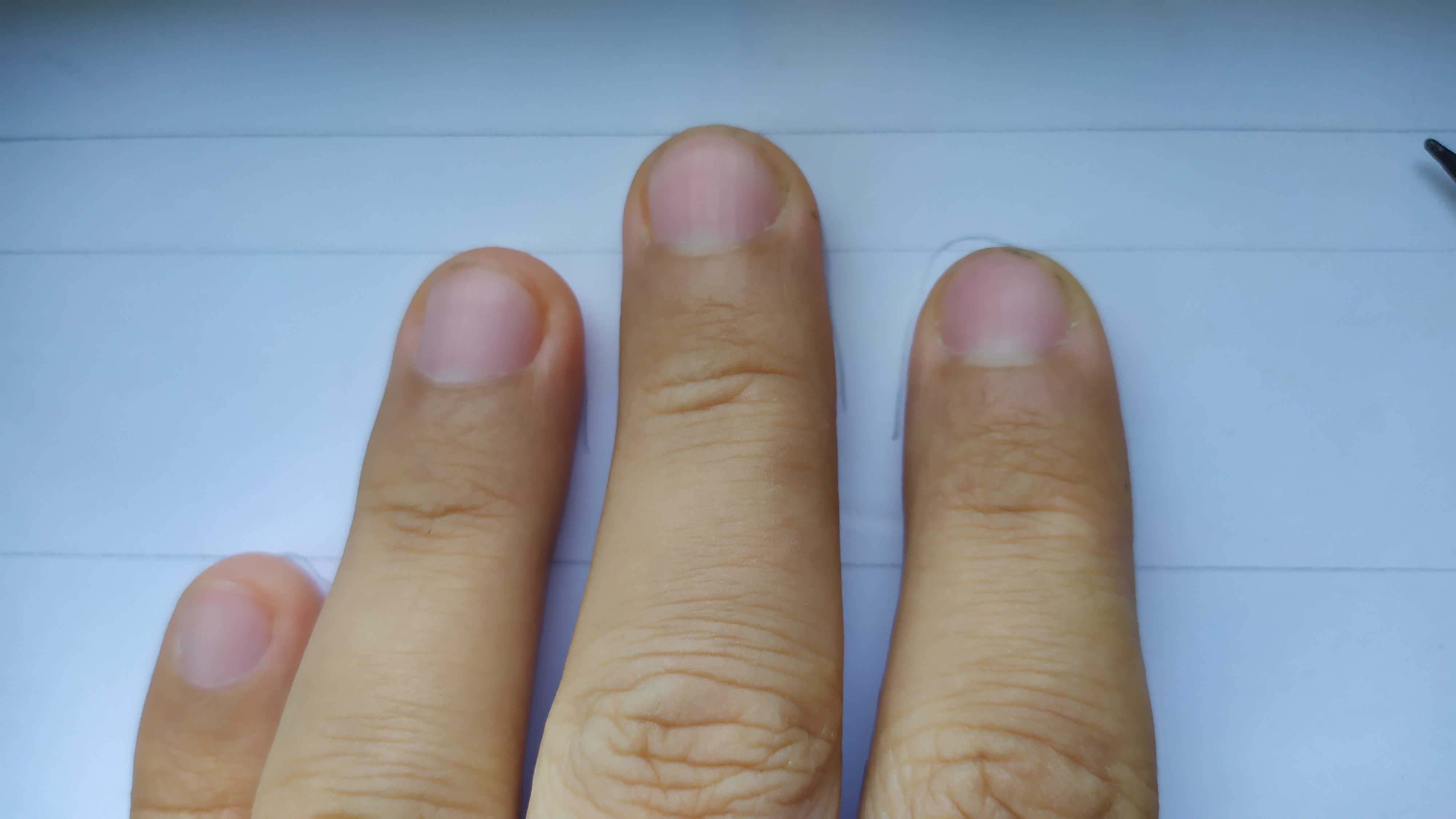
Here you need the coordinates of the buttons along the Y axis, or rather the difference between the vertical rows relative to each other. But there is a nuance that is perhaps important for you - in most men, the ring finger is longer than the index finger, and in women it is a little different.
Wikipedia: Finger Index
What Does It Matter? You may need to adjust the arrangement of the vertical rows to suit your individual needs. It was easier for me, there was no need for adjustment:
This may seem like an insignificant nuance to you, but such small details make up the constructor called "My Ideal Keyboard".
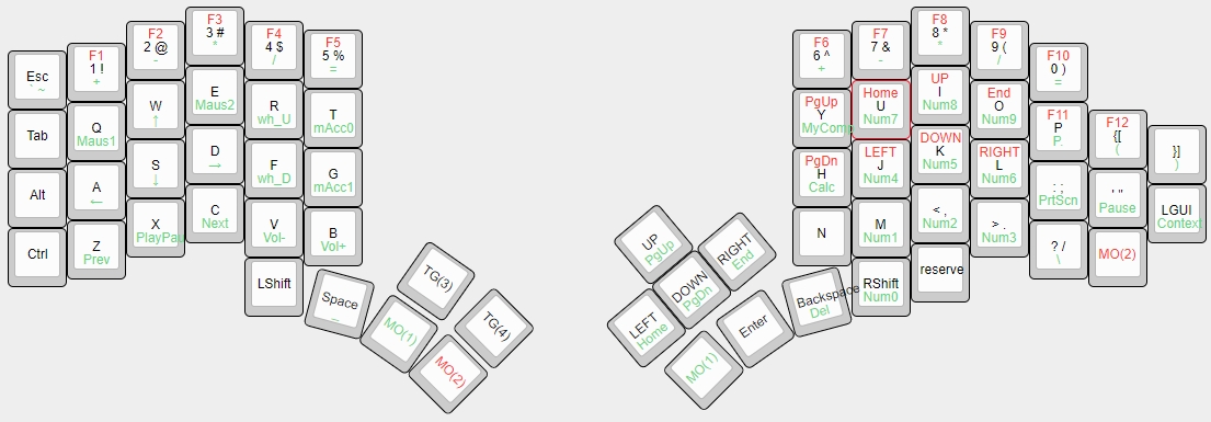
After numerous adjustments, I got it like this:
You have far from immediately, but gradually, your own version of a convenient layout will be developed. I'm just convinced that keyboard ergonomics cannot be universal when everyone's fingers and the type of work they do at the keyboard are very different.
Perhaps I will give an example that is not the most successful, but it is indicative. For Formula 1 pilots, seats and backs are fitted with bodies made from their casts, and not the so-called "sports" ones produced on the factory assembly line. Indeed, why?
Why did I implement a separate block of cursor keys besides those pressed through the MO (2) modifier? I designed the keyboard to be versatile and playable. Try to play "X3 terran conflict" / "X3 albion prelude" with cursors through the modifier and you will howl. You can reassign the buttons, I even made the fourth layer just for the game, but it turned out not very convenient. In this game, almost the entire keyboard is involved, whoever played knows.
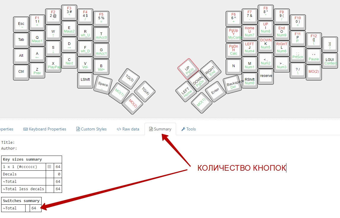
We can find out the resulting number of buttons:
Let's start shopping
And now, knowing the number of buttons you need, it's time to choose and buy components. Mechanical buttons differ in the required pressing force, volume and tactile sensations. Here is an article about them:
MECHANICAL SWITCHES
And after reading it, I strongly recommend that you rush through the shops that sell keyboards with mechanical switches and your own fingers to feel the difference between blue, brown and other switches. I was completely satisfied with the brown Gaterons, and I bought them. But not our hucksters with a margin of 300% -500% and even higher. Aliexpress has everything, you just need to try hard to search.
I do not urge to buy the components we need where I took it - you can take it wherever it is more convenient for you. But I will share the links.
Gateron switches on Ali, which I bought:
Gateron
There are the following types of button caps:
Everything you need to know when choosing a keycap profile
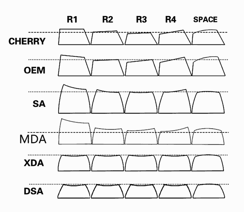
I tried different, but settled on the lowest DSA, they are the most convenient for me! Remember, you can and most likely will be different. Remember? We go to the store and try, try. This is an important building block of your keyboard's usability. I took it here, the quality is good:
PBT DSA
The next thing we need is ATmega32U4 5V 16 MHz. There are many modifications of them:
Atmega32U4
It will be enough for me with my head:
Pro Micro ATmega32U4 5V 16 MHz
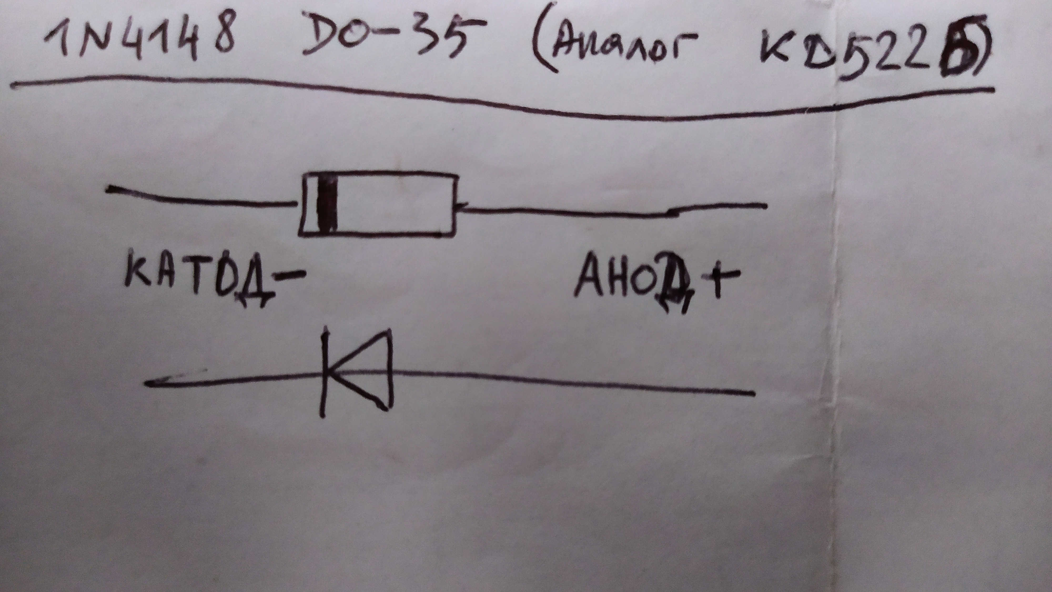
Diodes. I didn't bother with running around radio stores, I also ordered on Ali:
100 pcs 1N4148 DO-35
Next are inexpensive and optional, but very important nuances of our future keyboard.
Switch Grease - Reduces noise and improves typing feel for the better. Briefly about how to lubricate switches:
I bought this grease on a tip, I didn't have to regret: Grease .
Rubber rings for caps.
Needed to reduce noise from printing, I took white 9x4x2.5, no complaints:
Rubber rings
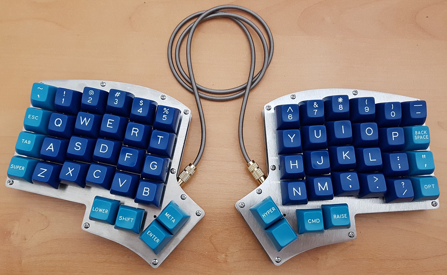
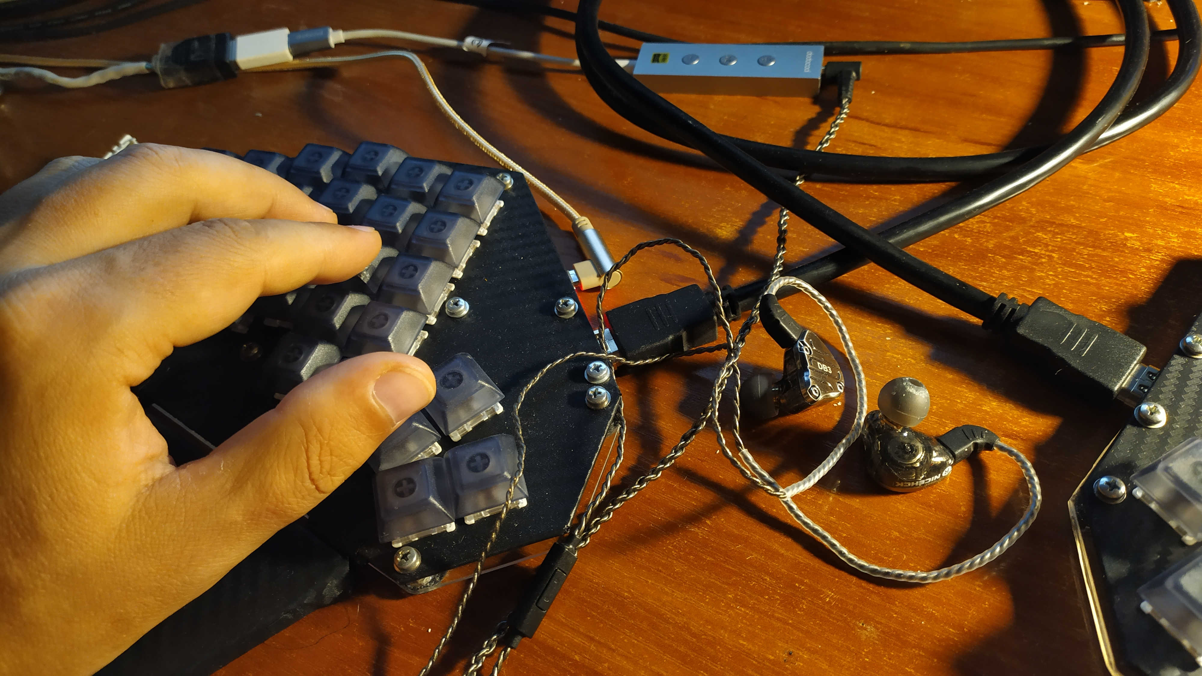
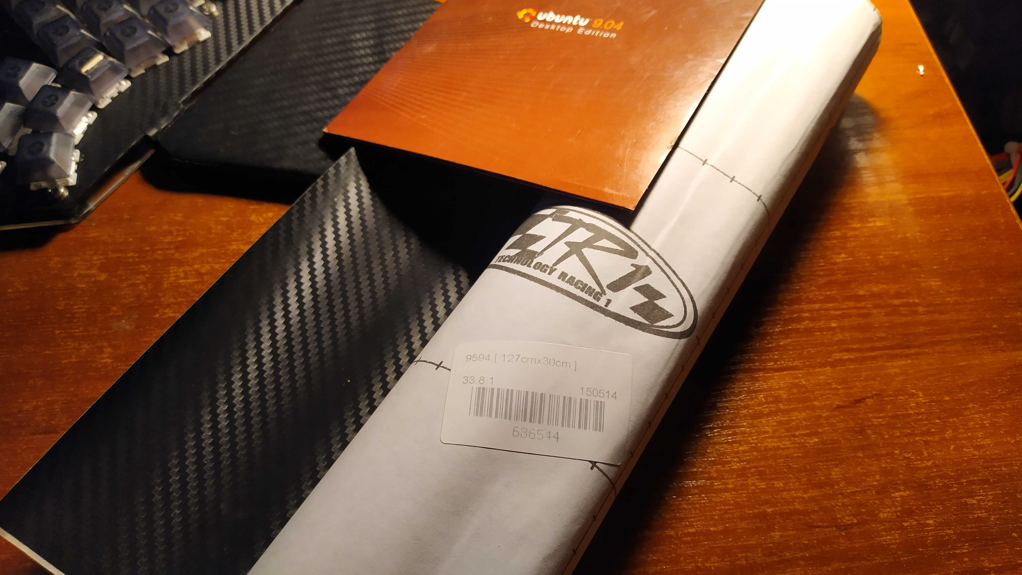
Micro USB cable for connecting the board to a computer. So I have a lot of them, but I needed a corner one, it is much more convenient with it (see the photo at the beginning of the article):
Micro USB cable
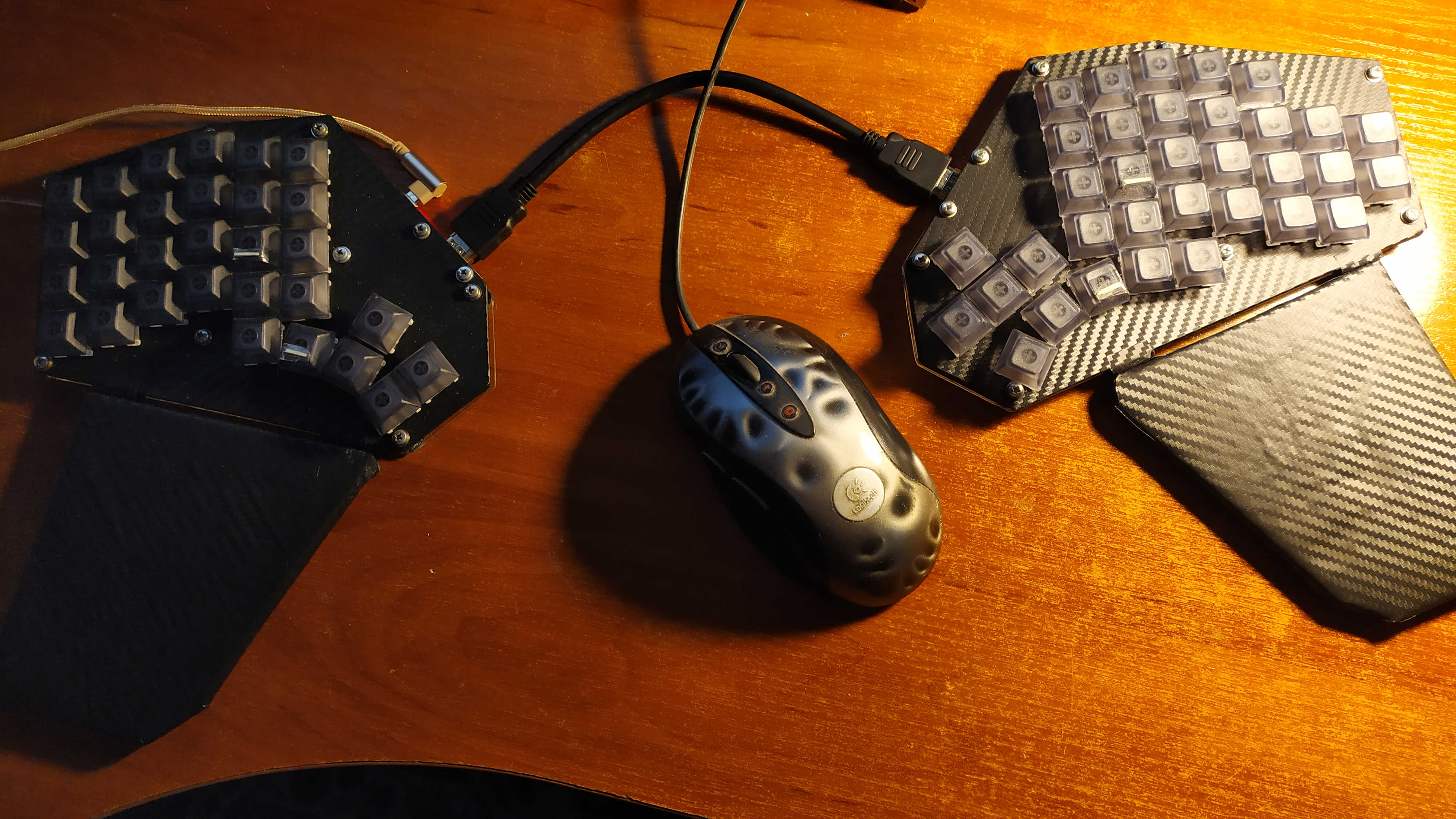
I made the keyboard divided into two blocks. These blocks needed to be connected with wires. At first I connected the blocks with a daisy-chain from a computer CD drive.

A temporary solution, I do not recommend it for permanent use. It is better to make a detachable connecting cable, it will be easier in the future. The HDMI cable came up well, it had 19 cores with the required 12 (5 rows + 7 columns). I really didn't want to cut the cable, and I purchased connectors for it:
HDMI 19 Pin connector
Question: can I use a long HDMI cable? It is possible and even necessary! Just look at the photo: The
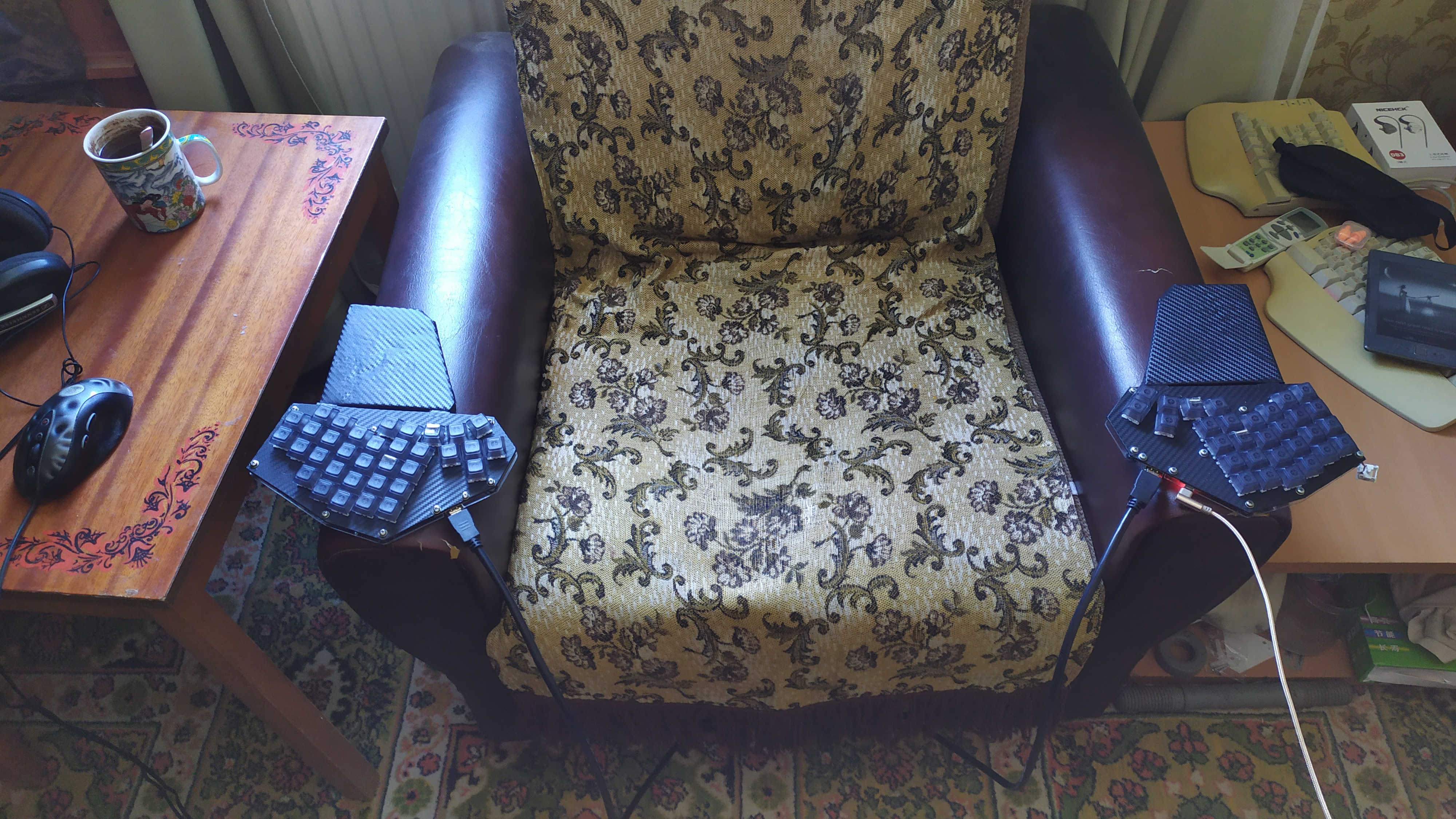
keyboard does not slide off the armrests. The wrists are resting on the palm rests. Each stand holds its own keyboard unit with two magnets. The HDMI cable does not interfere with your legs at all. Nothing crawls away, it turned out just cool.
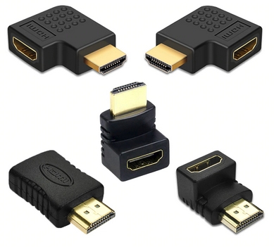
You may need such adapters:
HDMI cable-adapter 270 180 90 degrees
You can choose any other connection method that suits you best. See how one of the Reddit users got out, just keep in mind that there are only 10 cores in this cable:
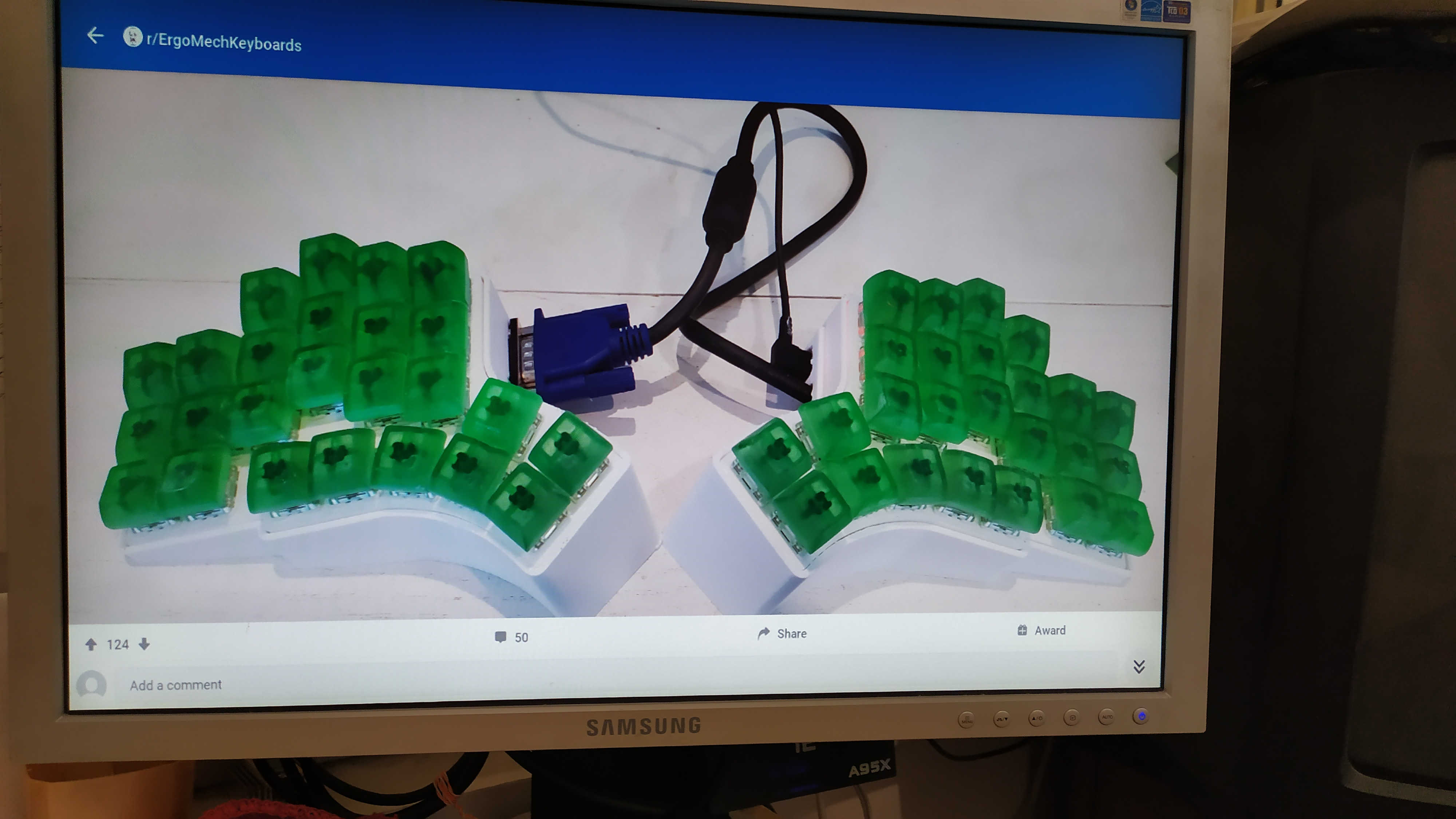
I took a picture a long time ago. That post hardly exists anymore, so only in that capacity.
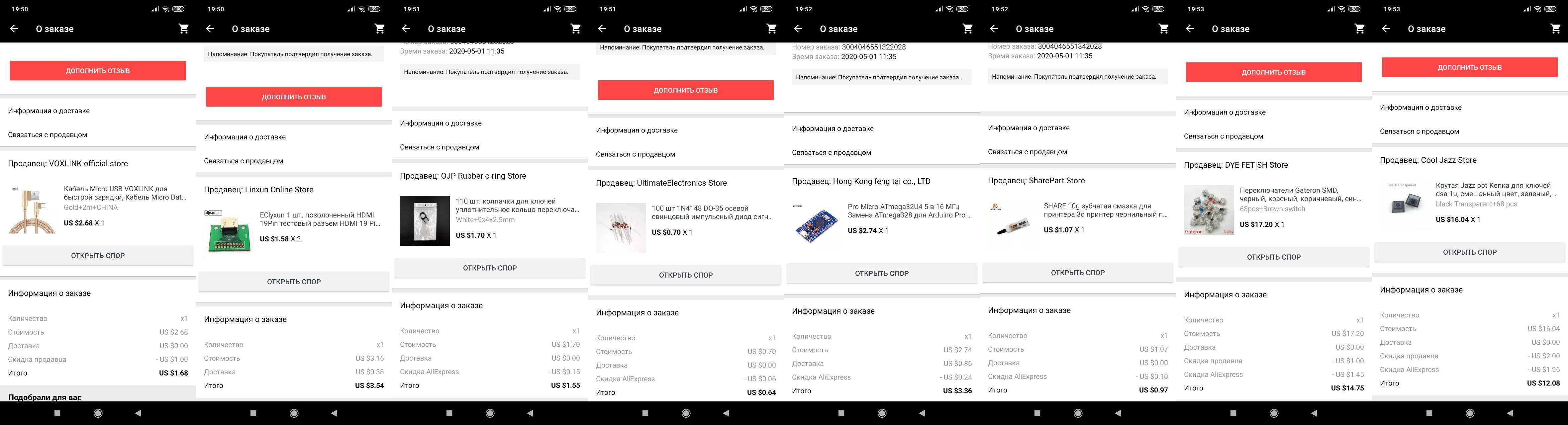
Let's add up my expenses, it turned out ~ $ 38.5:
Purchases will creep from China for about a month. And we have plenty of time to make our keyboard case.
Making the top panel and keyboard case
Back to our online builder. We need to enter the data, what type of switch we are using:
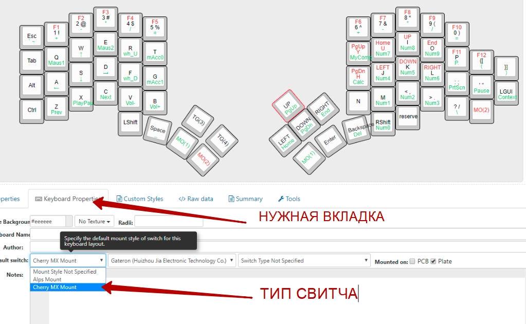
And the following picture:

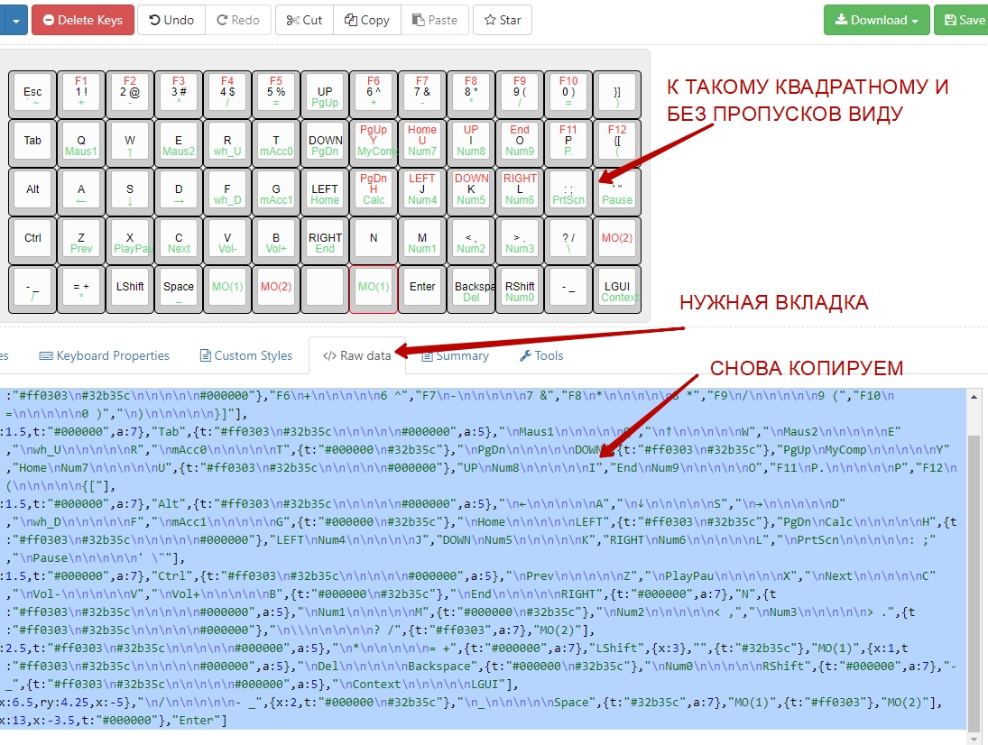
Now we need this tab:
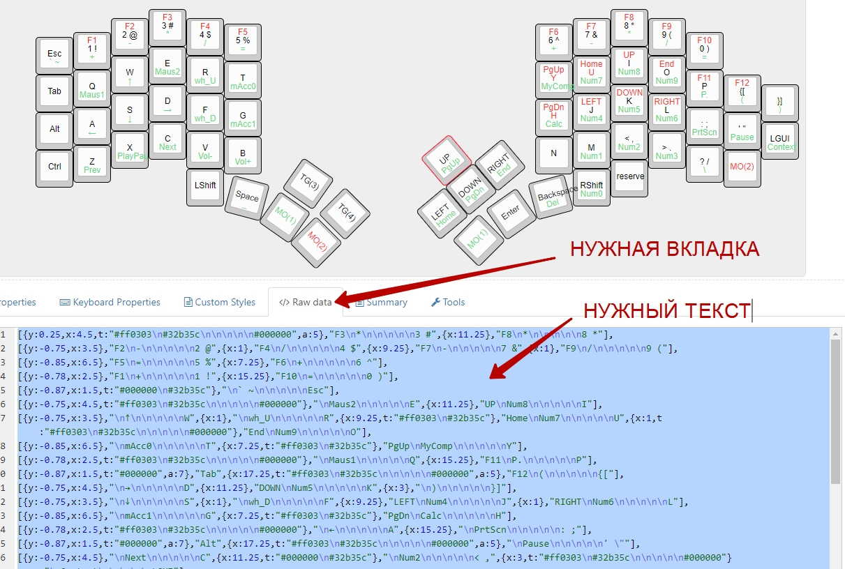
With the combination Ctrl + A, select all the text and copy it to the clipboard Ctrl + C. Open the link:
Plate & Case Builder
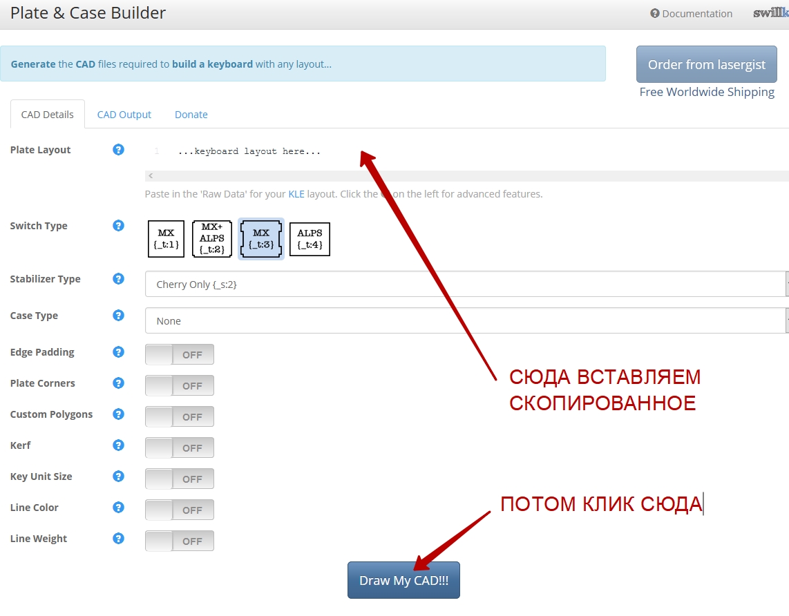
And we get this:
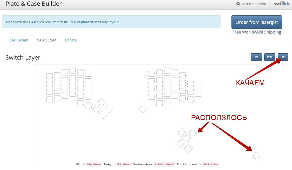
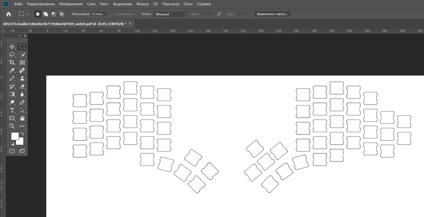
No luck, the image has crawled. It doesn't matter, we'll fix it in Photoshop:
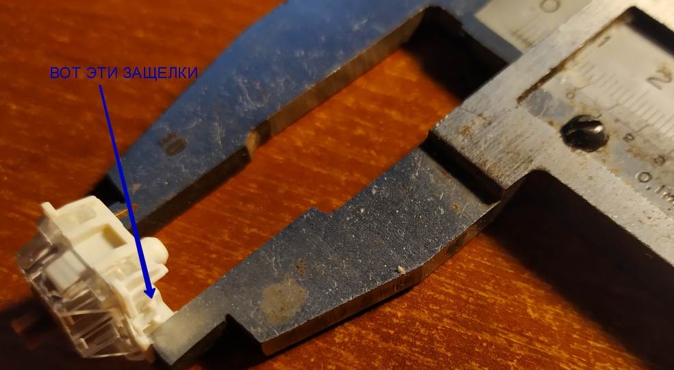
Send it to print. We measure the size of the squares on paper with a ruler - everywhere should be 14 mm. And the distance between the square holes must be at least 5 mm, otherwise the caps will touch each other. I still have printouts of intermediate results:
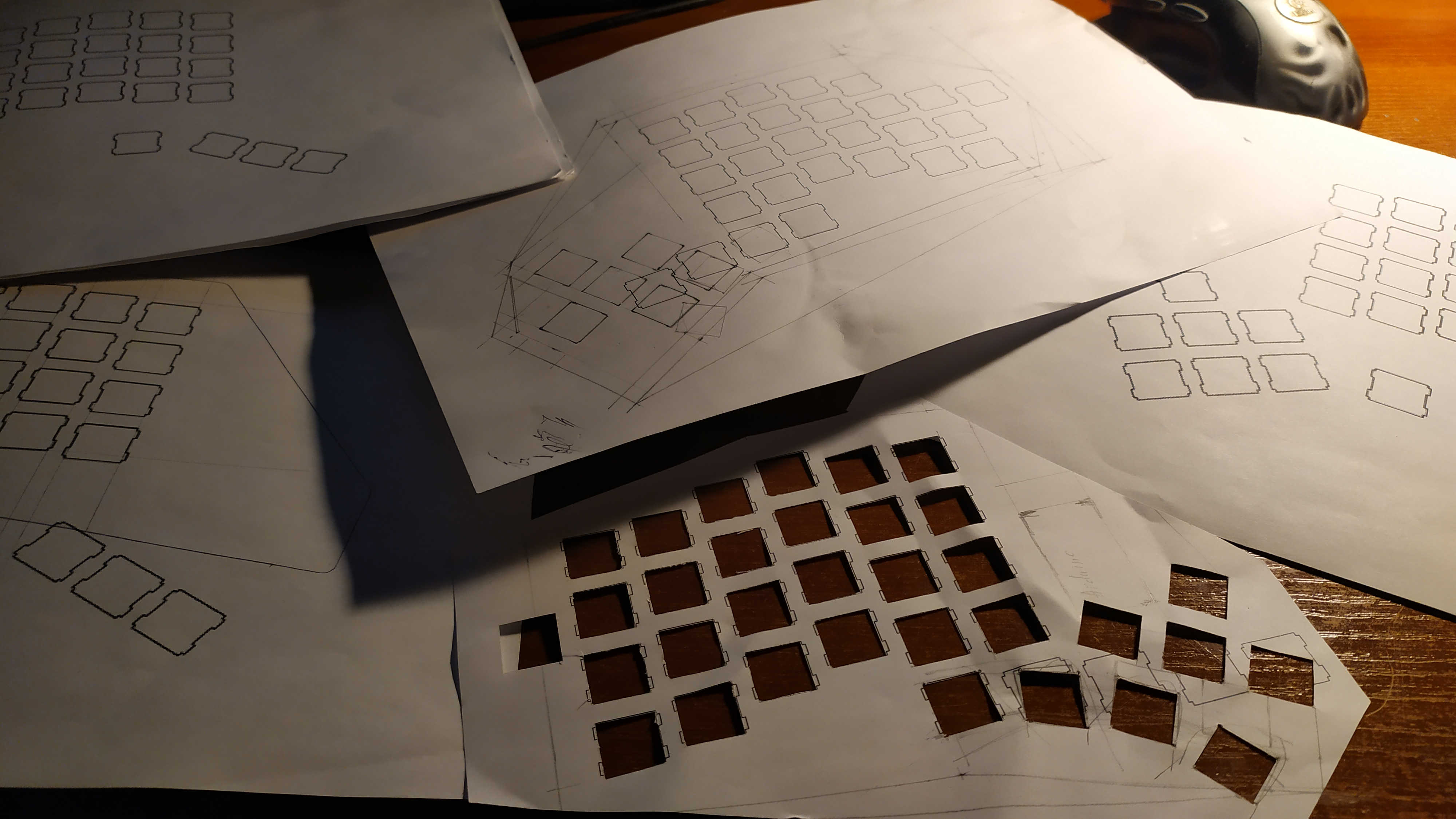
We have just printed a stencil with which it will be convenient to make a marking for the holes for the keys. Next, you must select the material for the top panel of your future keyboard: aluminum, fiberglass, plexiglass, acrylic, polycarbonate ... There are a lot of different materials, but I chose plexiglass. Use material no more than 2 mm thick, otherwise the buttons will not stick to the plate - the latches will not be able to catch.
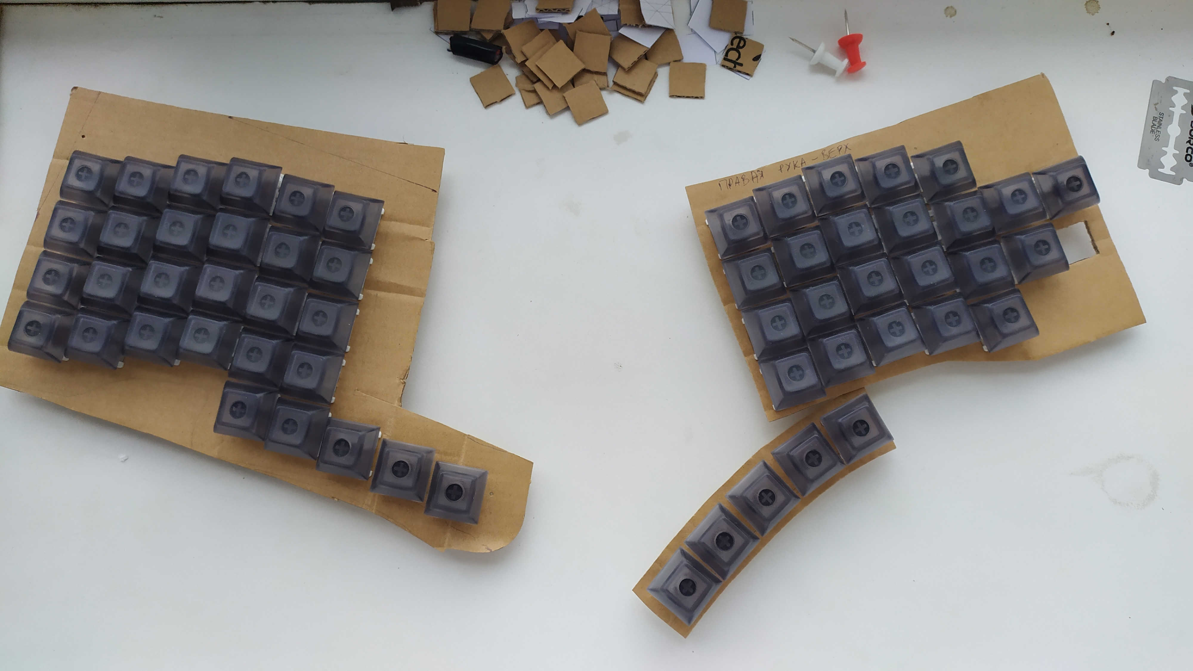
But before you start working with your future panel, I strongly advise you to try on buttons on a piece of cardboard. So you will get a rough idea of the convenience of the location of the buttons of your future keyboard.
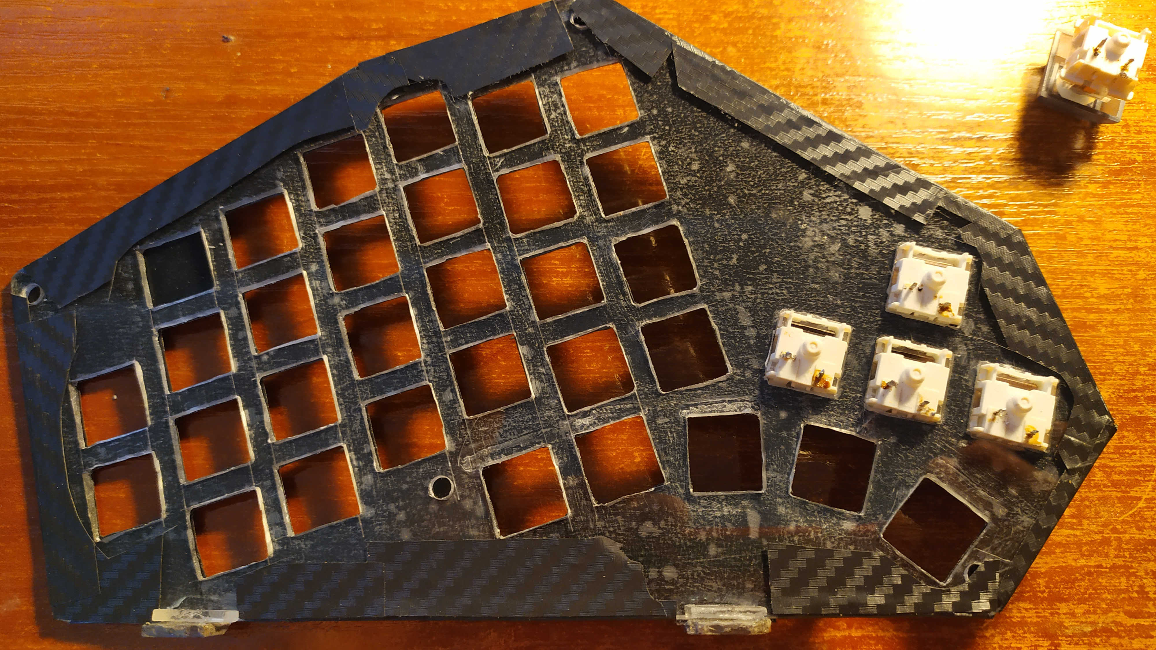
When you finally decide that you have chosen the option that suits you completely, you can start making the keyboard top plate. I had it like this:
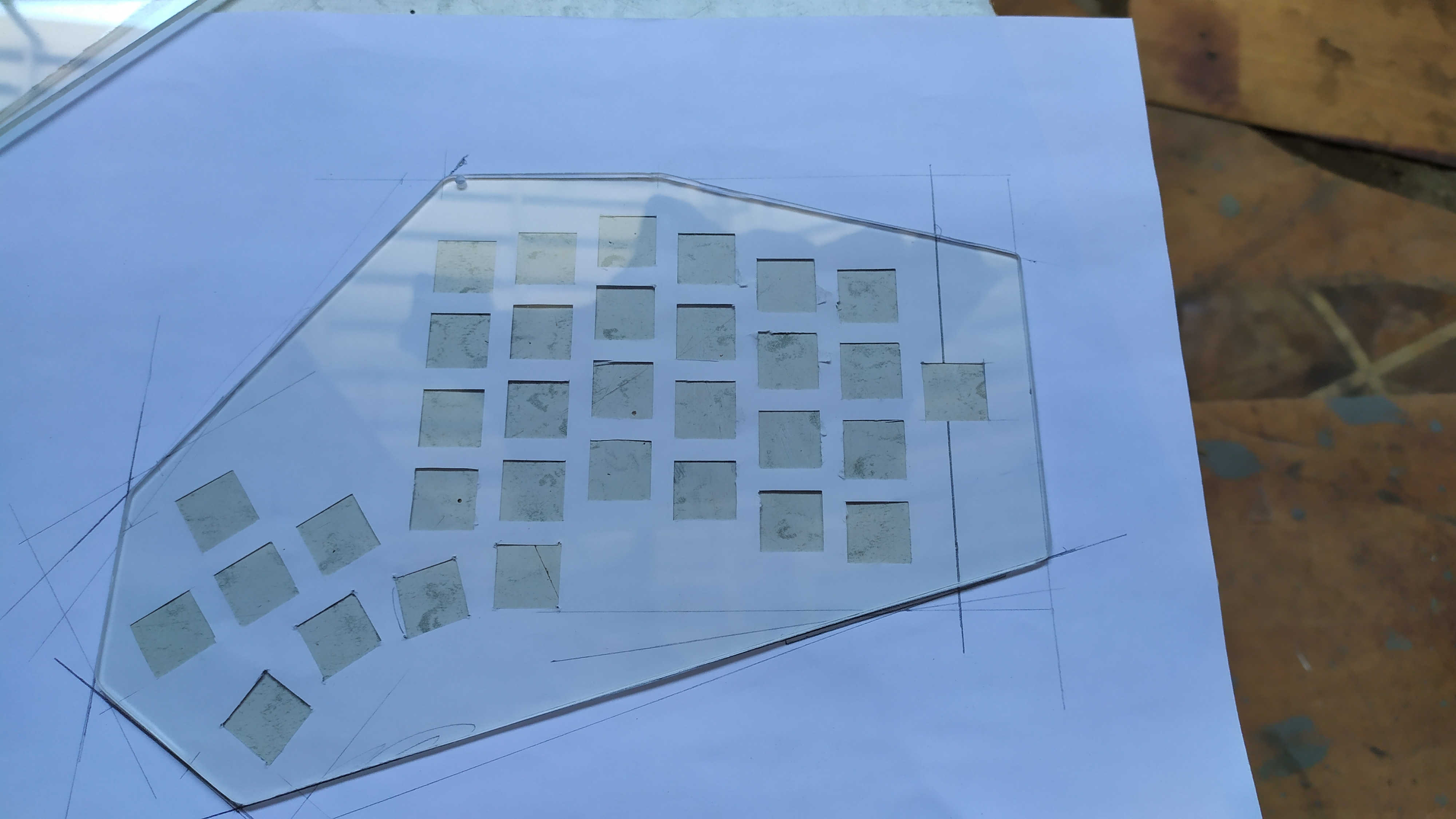
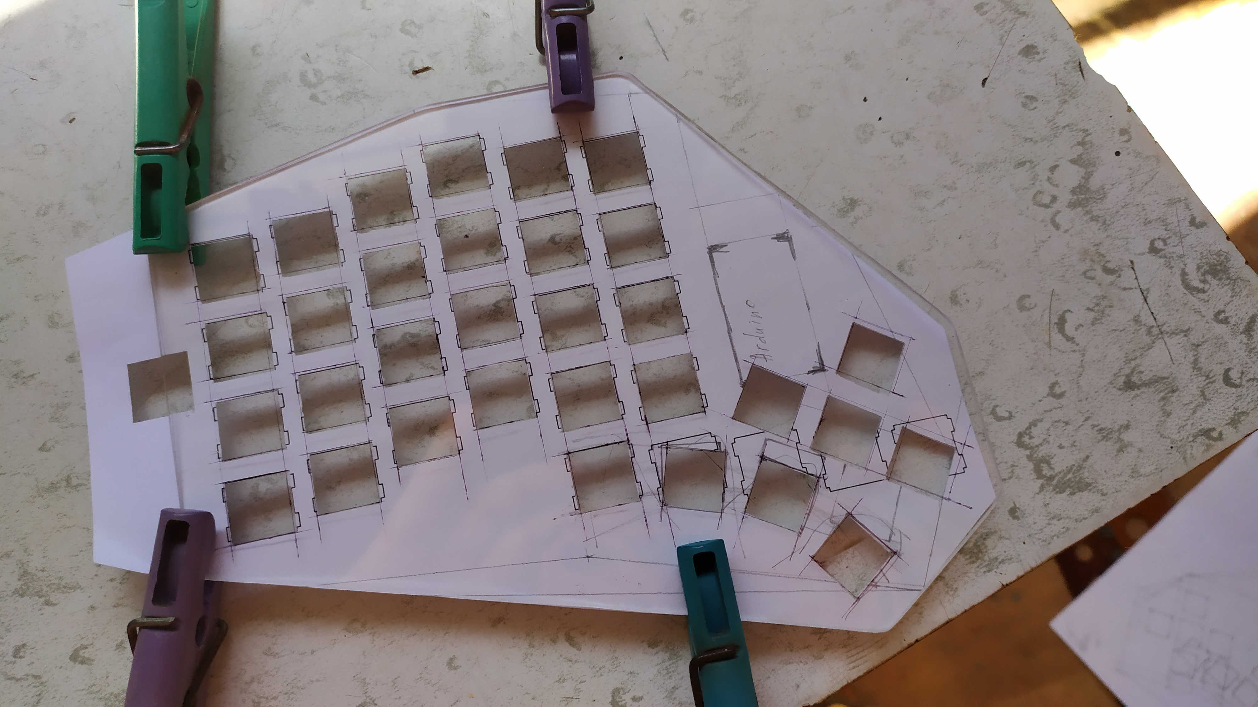
You can apply markings on plexiglass either by scratching with a scribe or simply by drawing with a pen - that's enough. Then I melted the holes with a soldering iron, and brought them to size with a file. You can also work as a dremel. Do not forget, it takes a month for parcels to travel from China. There is nowhere to rush, so I did not rush in search of laser cutting.
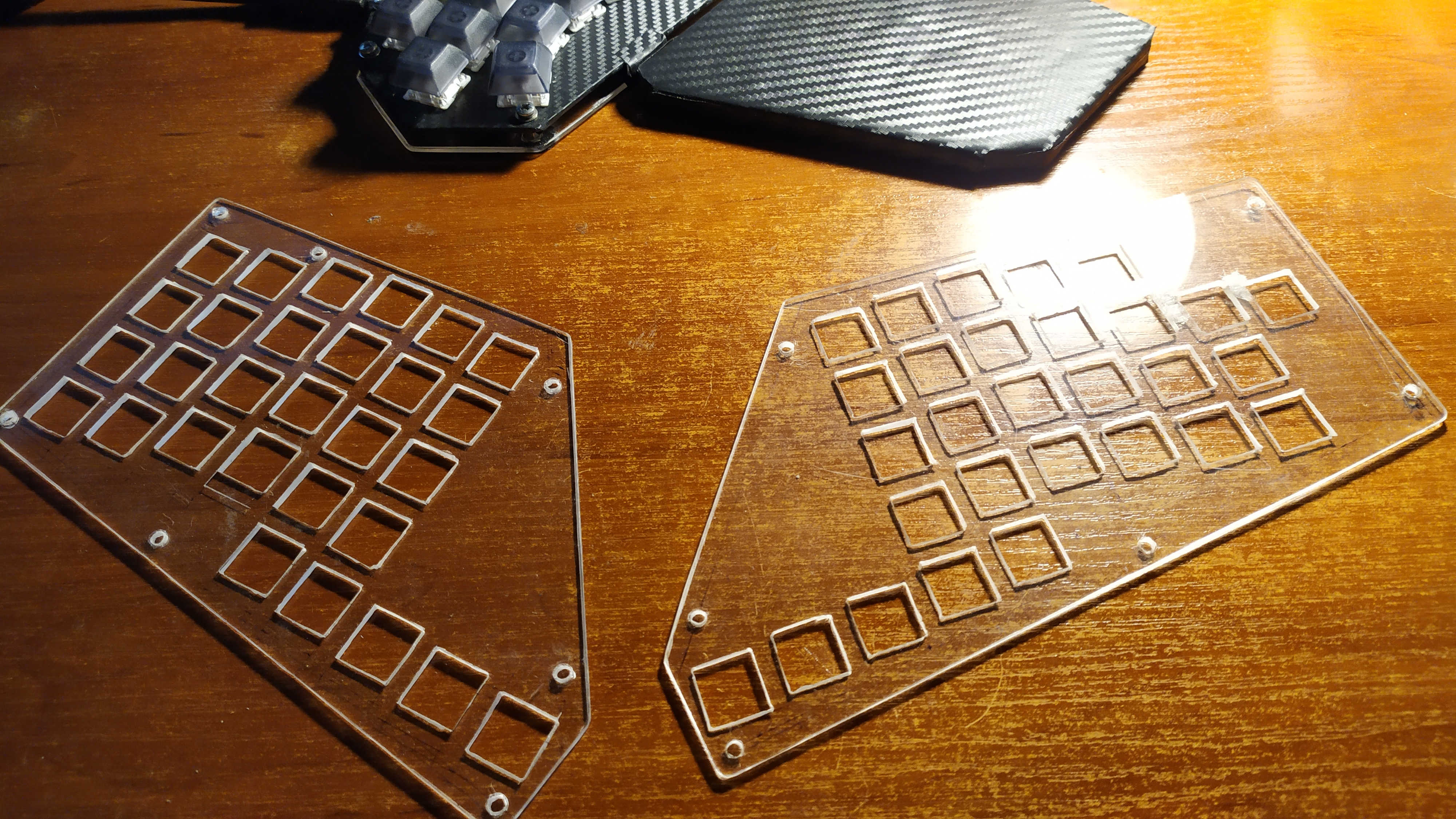
These are the top plates of the first option, into which the buttons are inserted. The bottom plates are exactly the same in size, only without the holes for the switches. It remains only to come up with a way to attach the upper plates to the lower ones. I have implemented rack mounts like motherboards in computer cases. I drilled holes in the lower plates of such a diameter that an M3 nut was placed in the holes.
And we glue our nuts into these holes using superglue.

We screw the racks into the nuts.
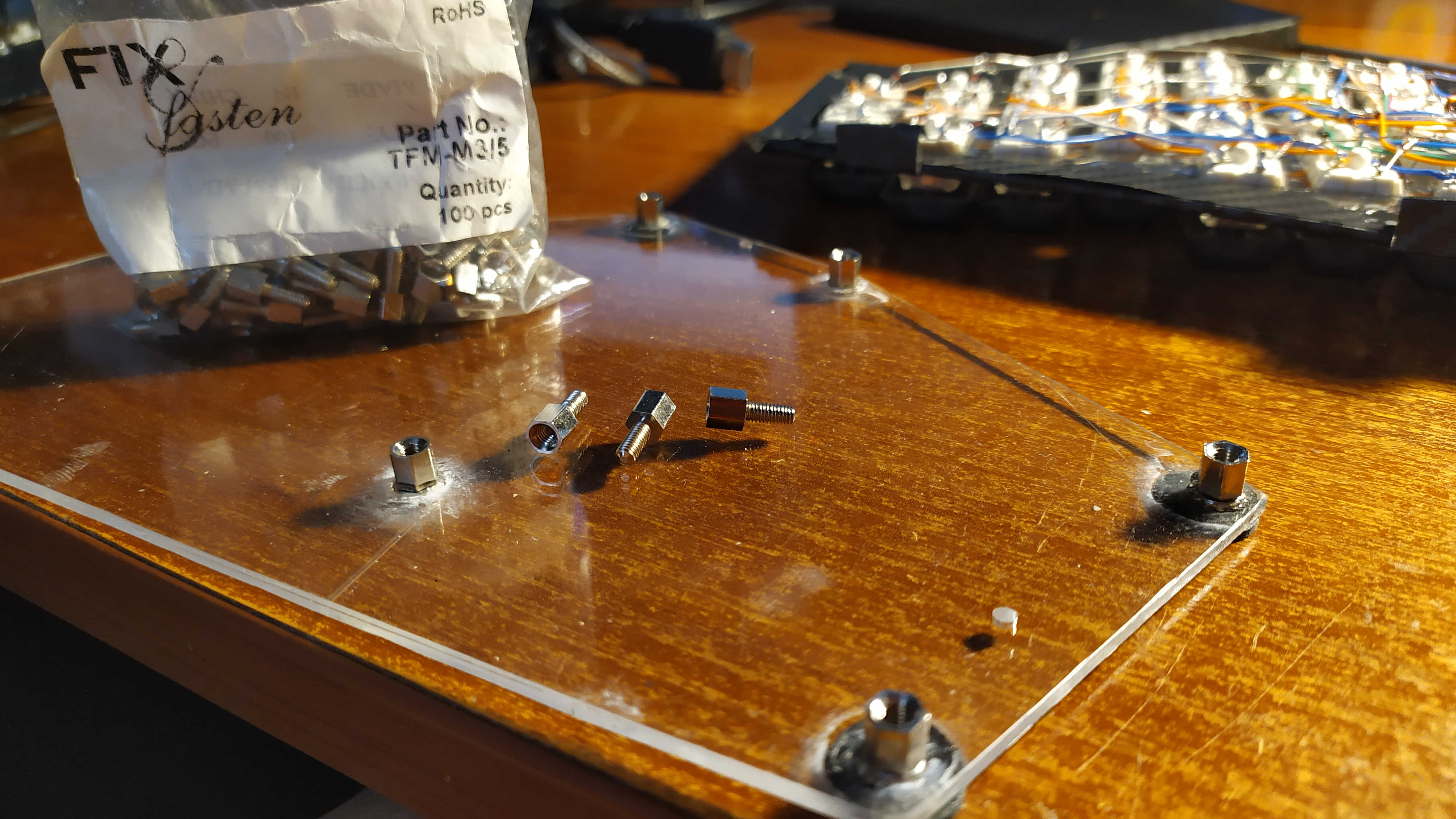
I chose the racks in height so that there would be enough height for the switches hanging from the top plate.
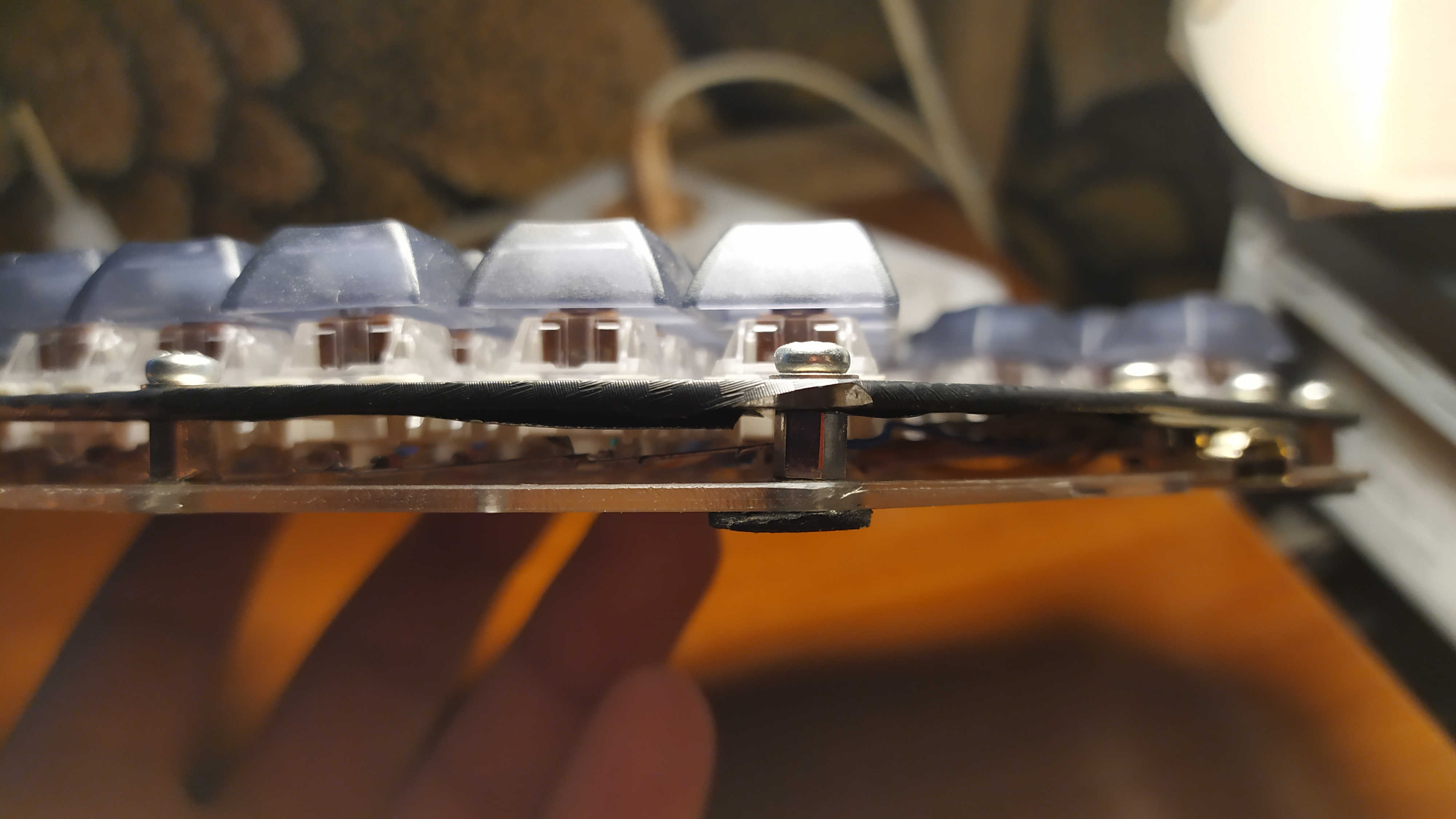
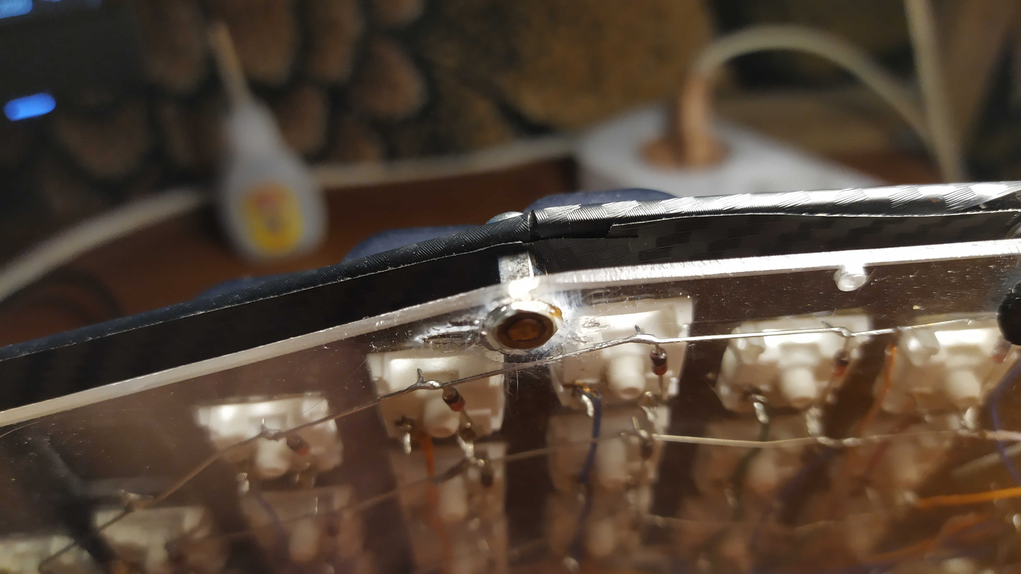
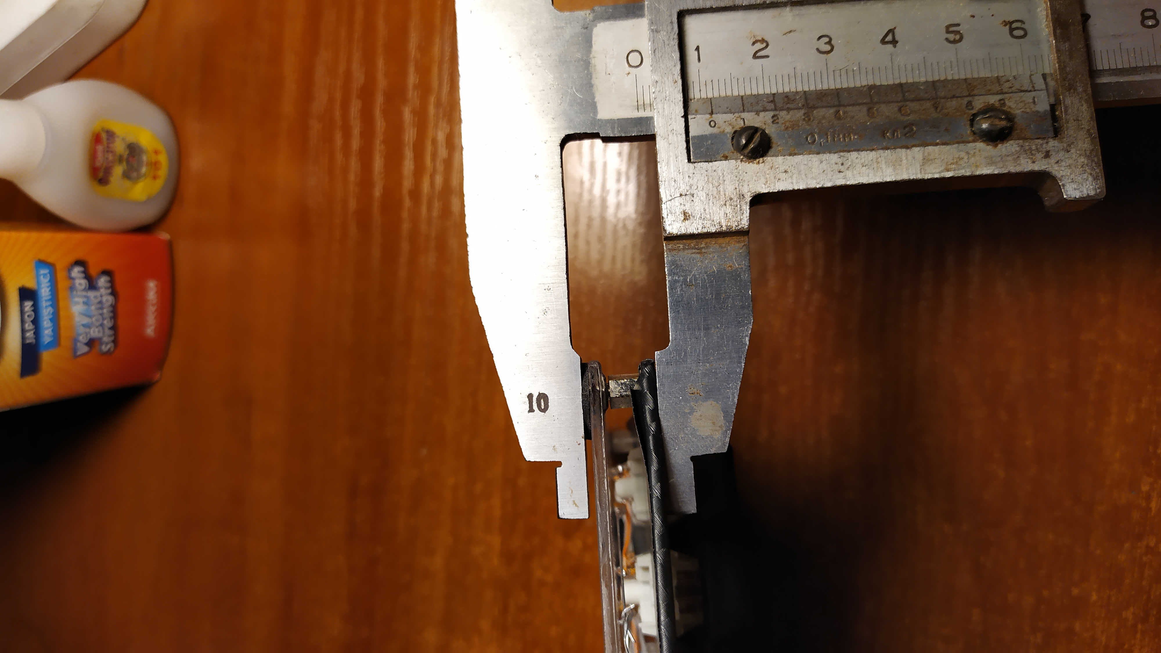
The lower the height of our keyboard, the better for our hands! The body height of my keyboard with rubber feet is less than 12mm:
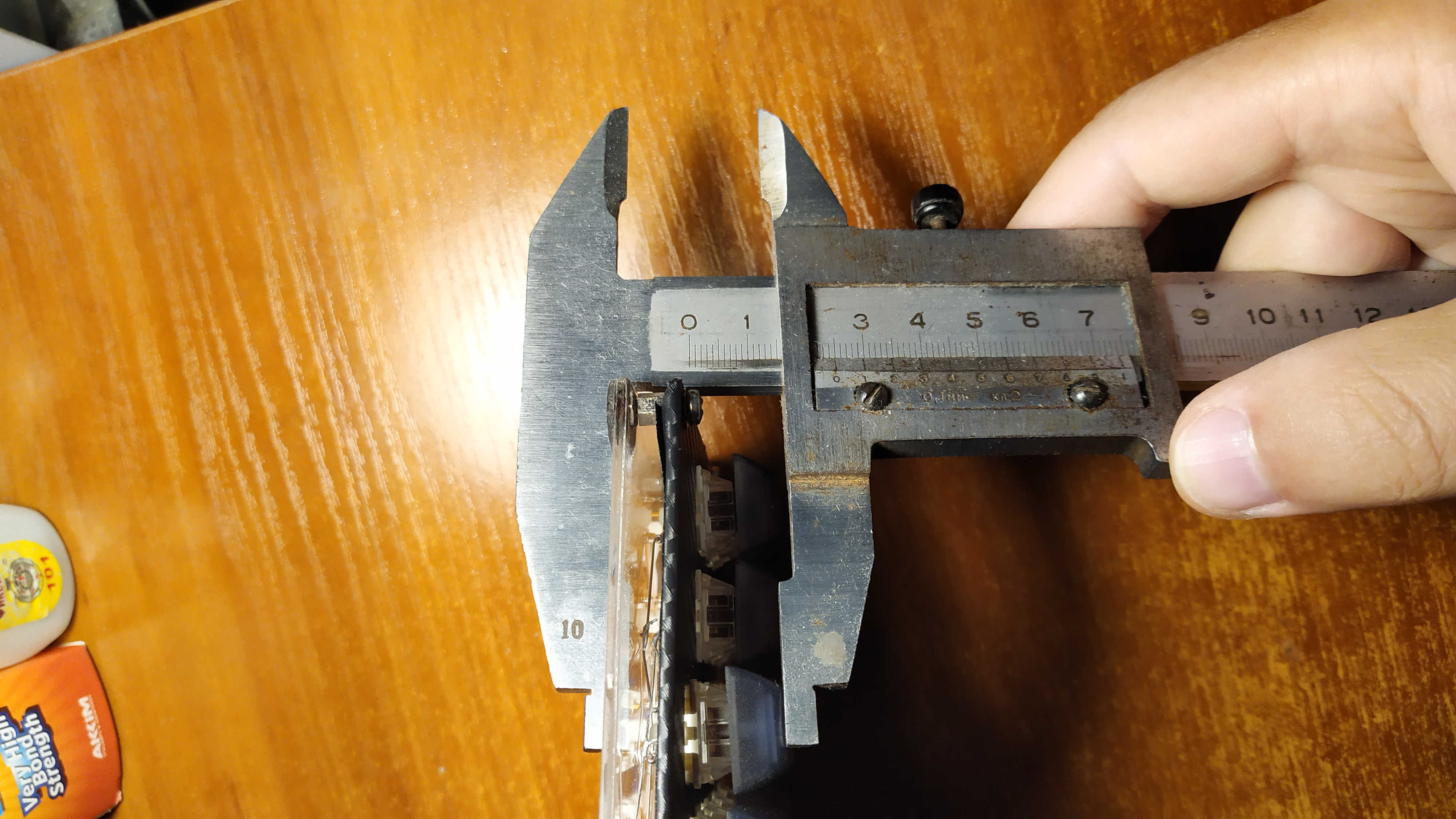
Total height is 25mm:
In the future, I plan to find somewhere a rubber / rubber seal with a square section and glue it around the perimeter of the bottom plate, thus making the wall of the keyboard case. I just didn't have time yet.
Option 2 before covering with a film:
Next, a completely optional thing - I covered the top panel of the keyboard with film. But in a couple of little things, she still helped: there is no more glare from the table lamp and now you can not see the red LED glowing on the working arduino.
I don't see the need to explain how to glue the film. All that was required of this tape was not to distract attention while working. And she performs this task perfectly. It was bought on Ali four years ago.
The material that went to the palm rests. What is the name, I have not the slightest idea. Foamed something there. Wrapped it with tape, and glued the film on top.

I put small metal washers under the scotch tape in two places, and in front of them I glued neodymium magnets broken from an ancient hard disk to the keyboard case.
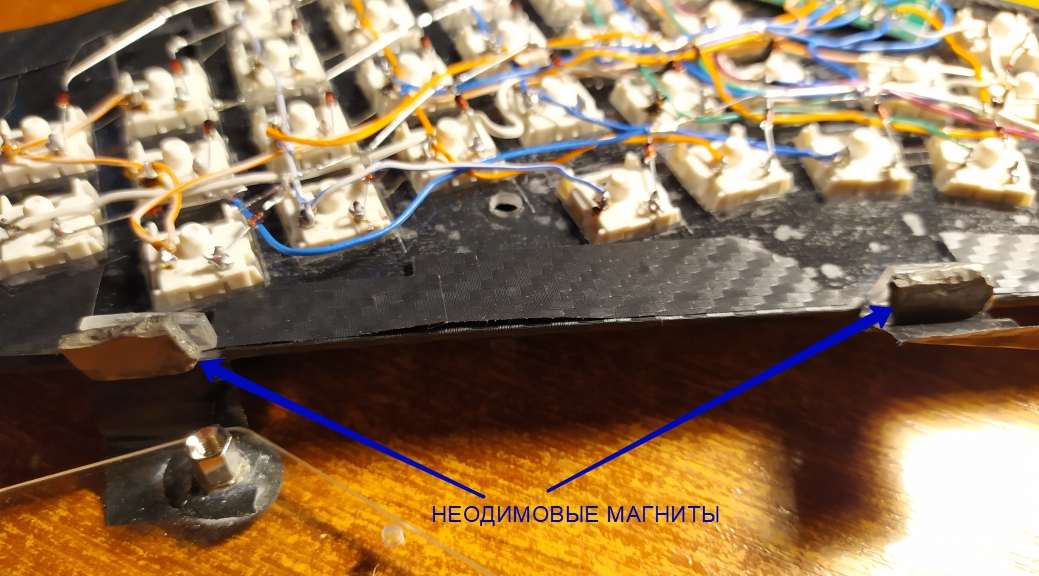
Now palm rests will not go anywhere from the keyboard - magnets hold very well. And if necessary, it is not at all difficult to remove the stands - you can definitely overcome the attraction of magnets. I strongly advise you to do it with magnets as well, you will not regret it.
Moving on to making the firmware
Returning to the online editor, we need this tab here:
Using the Ctrl + A combination, select all the text and copy it to the clipboard Ctrl + C. With the help of the copied text, we can see how our future keyboard will look approximately. Follow the link:
Keyboard Layout 3D Viewer
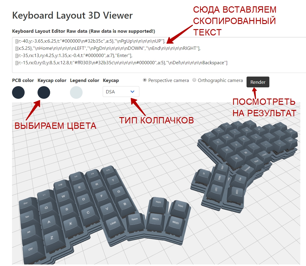
You can rotate the camera with the mouse and play with the zoom. In general, you will figure it out.
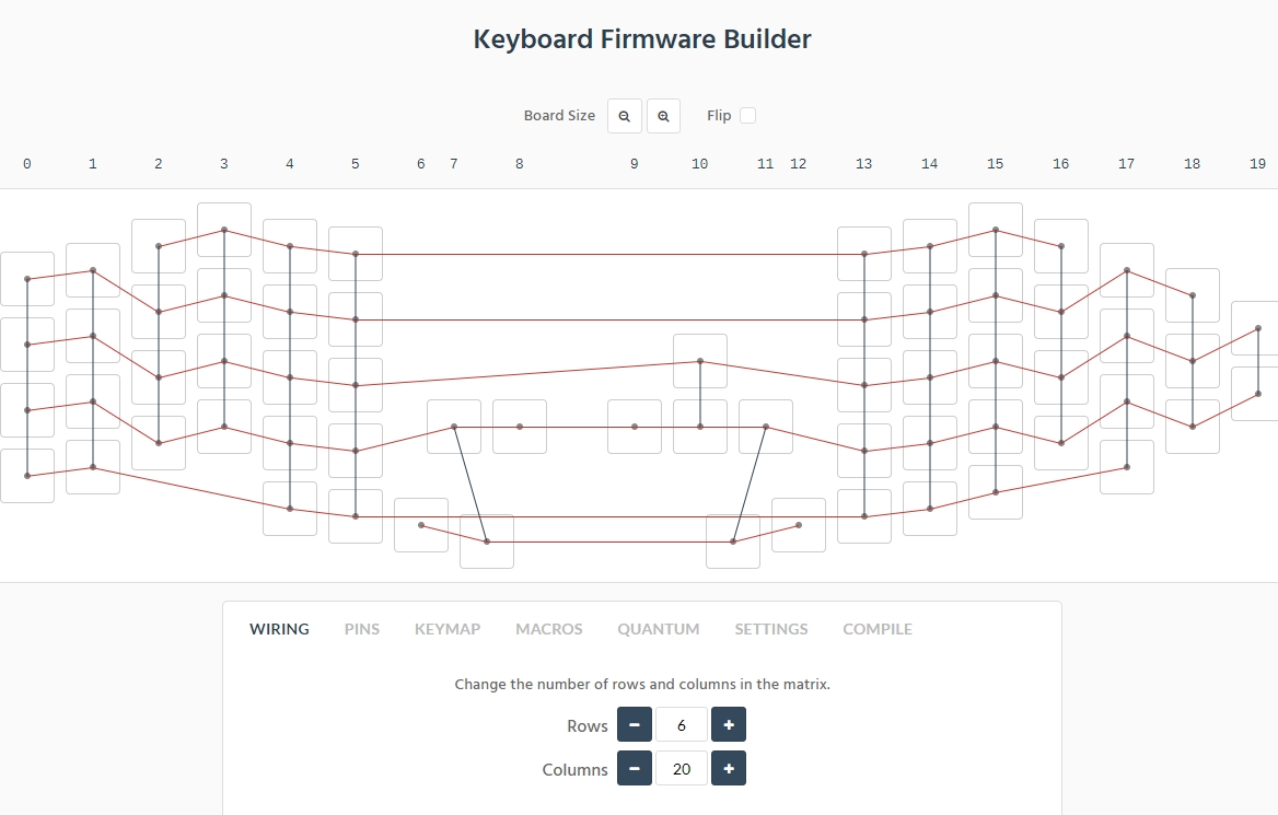
The next step, open in a new browser tab the link of the online designer of our firmware for arduina:
Keyboard Firmware Builder
Paste the copied one, as in the screenshot:

Automatically, such a clumsy and unsuitable for further use electrical wiring will turn out.
It is necessary to help the algorithm to work correctly, he himself is not able to cope. To do this, we return to the online designer and bring our keyboard to the form:
Reopen the Keyboard Firmware Builder tab and paste the copied one:
The result is excellent:
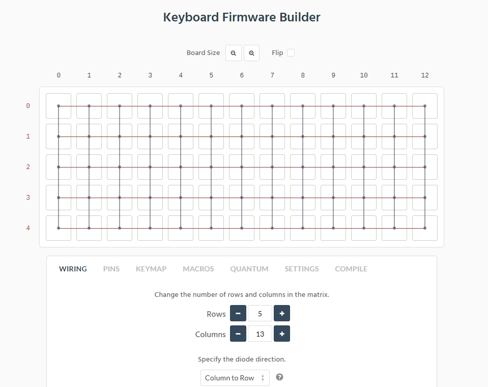
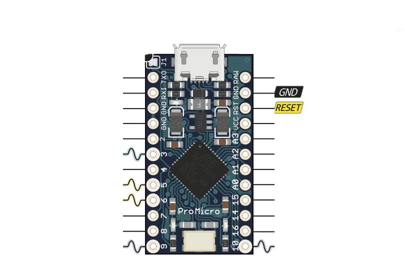
What you need. You must achieve a similar layout for yourself. Next, go to the PINS tab, in it we will indicate which contacts the arduins will use. Look carefully, if you bought the same board as mine, then you will have only such contacts as in the figure below:
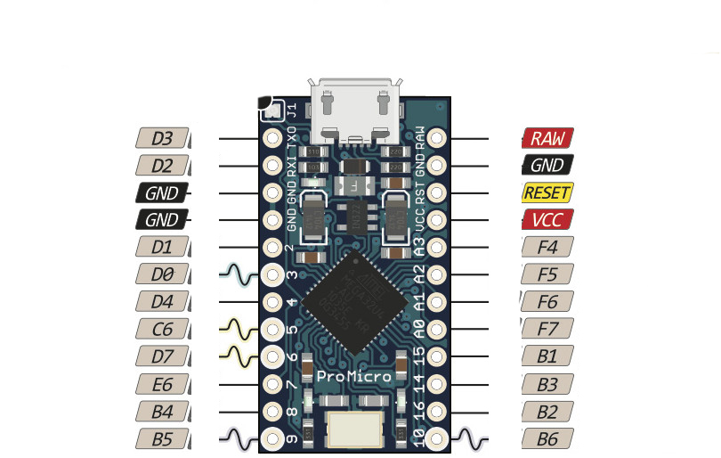
Based on what we have, we put the pins that are available in the ROWS and COLUMNS columns. Below is an example of an arrangement in the screenshot:
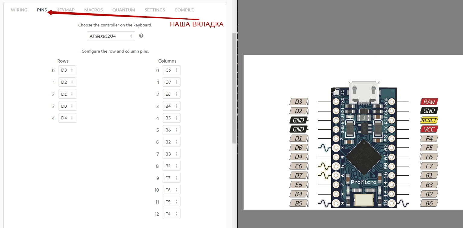
It is not necessary to arrange the pins in the same order as in the picture above. Do it in the order that suits you. The main thing is, do not make a mistake and do not indicate the pins that are missing on the arduino board.
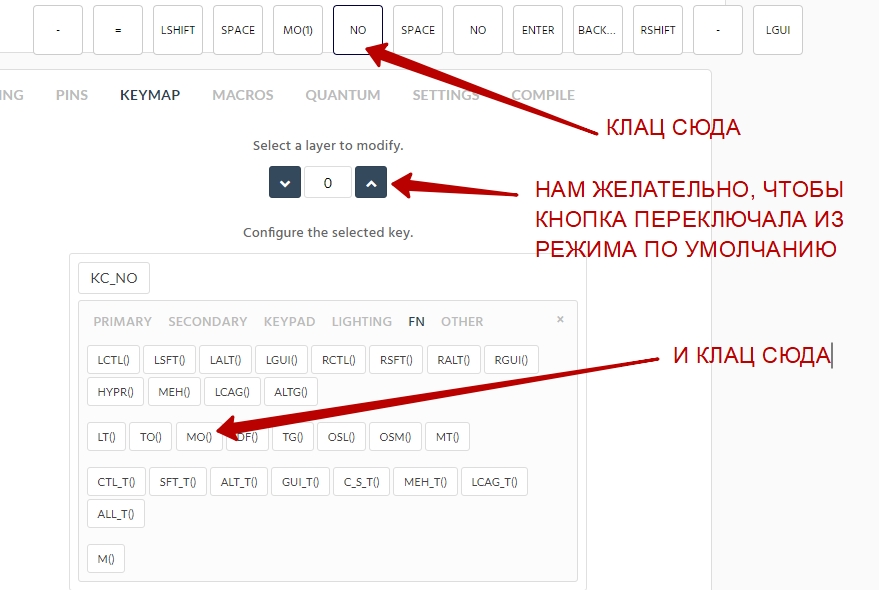
Go to the KEYMAP tab, in it we will set the behavior of the buttons:
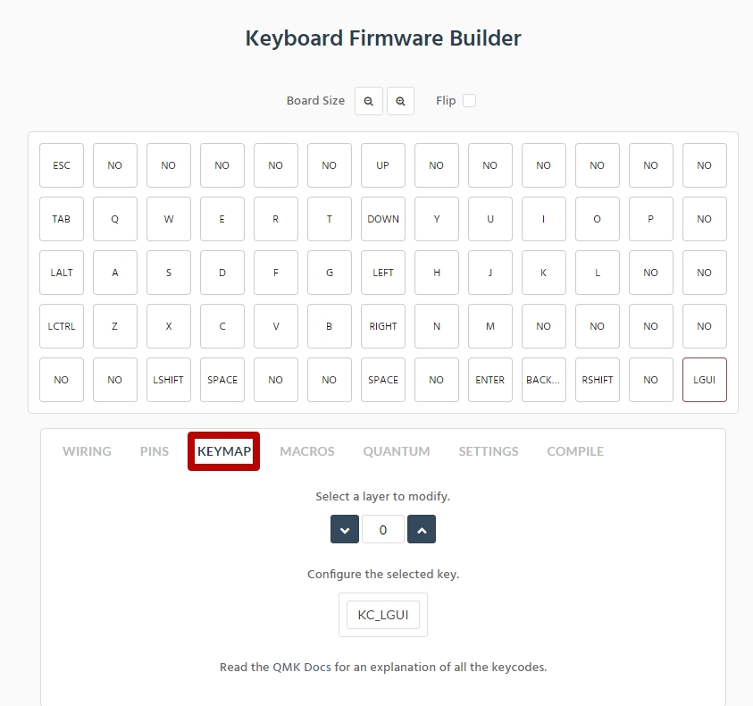
Partially, the constructor assigned the values to the buttons for us, we will finish the rest. It is very interesting here, you can think of so many things! Let's start with the elementary:
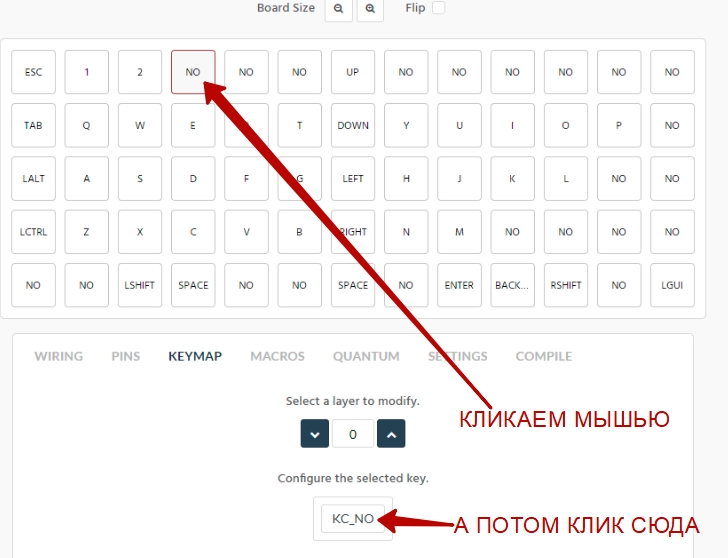
And then click:

And the button is assigned the value "3". Then, in the same way, we assign values to the rest of the buttons. Here's an example of how to make the right or left Windows keys:

This is all we had the main layout (layer zero) by default, let's now make the second layer.
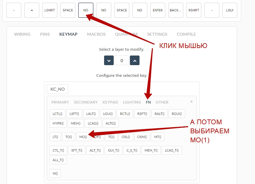
How to use this MO (1)? It works in the same way as the SHIFT key. Only the keyboard will give out what we program on layer 1. Start filling layer 1:

Make the DELETE key:
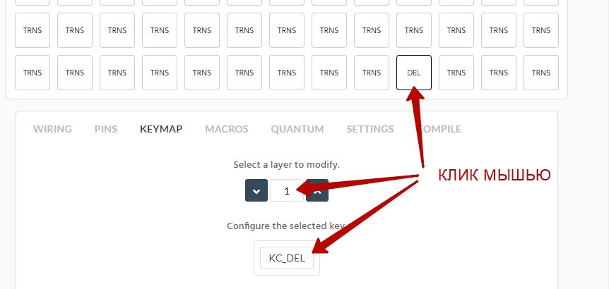
By default, this button works like BACKSPACE. But now, if we press it while holding down MO (1), the button will work as DELETE. It's that simple. Similarly, we assign values to the rest of the buttons. And not necessarily all. If we did not assign a value to the button on layer 1, then it will give a layer value of zero (which is the default). Let's make multimedia volume keys.
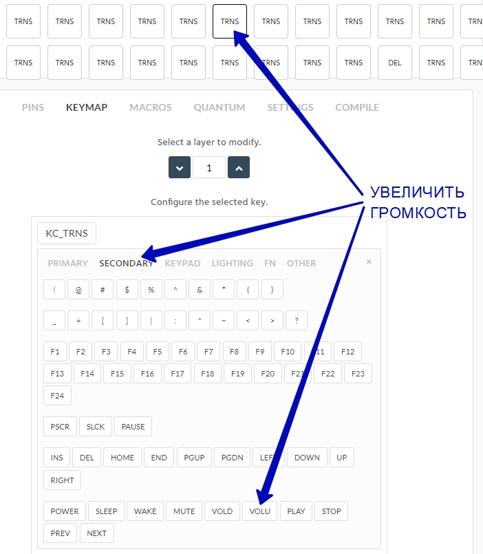
VOLD, VOLU is the volume control. Player control, for example Foobar2000: PLAY, STOP, PREV, NEXT. And that's all - global keys that will control the player even if you are working in WORD or playing a game.
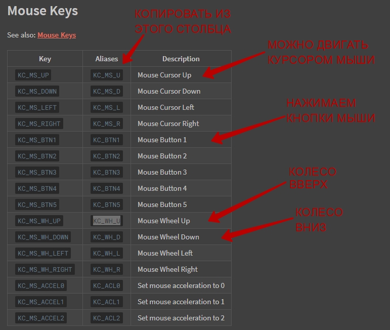
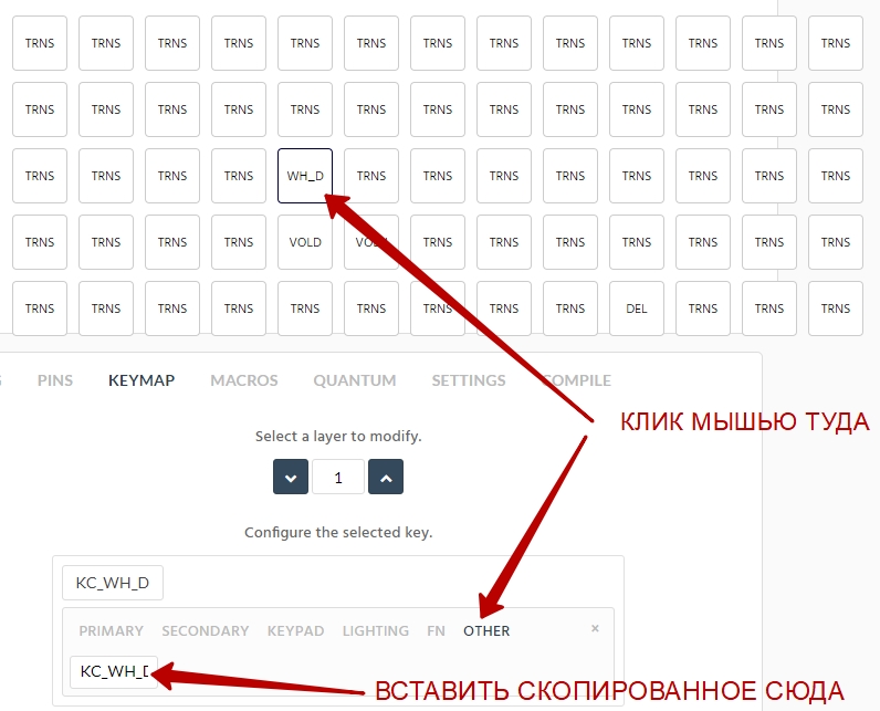
Further, there will be magic, inaccessible to conventional keyboards. Remember how often you had to remove your hand from the keyboard to the mouse to scroll (scroll) with the mouse wheel a document in WORD or a page in a browser. Often, probably? Open the link:
Mouse Keys
Now we will teach the keyboard to behave like a computer mouse.
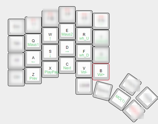
See what I can do with one left hand! I can move the mouse cursor (to be honest, I hardly use it), I can press the left and right mouse buttons (I periodically click the right one), I spin the mouse wheel (I use it all the time, I didn't even have to get used to it!) And control the Foobar2000 player and volume. At the same time, the palm does not move to the side by a millimeter.
With this, I think, everyone should be clear. Let's make the Ctrl + Alt + Del combination be pressed with one button! Not that it is very necessary, but knowing how to do it is useful.
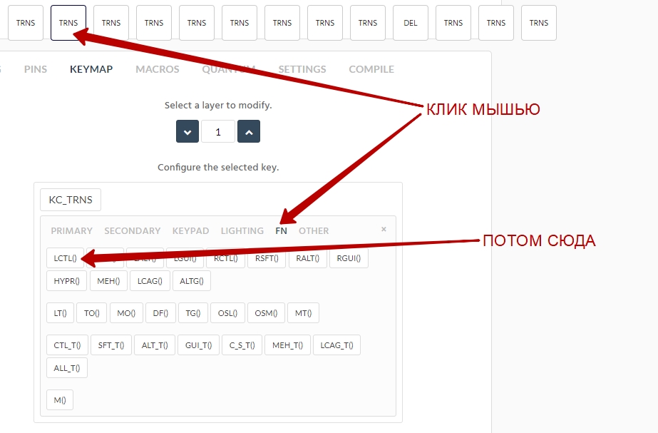
Next operation:

Modifier again:
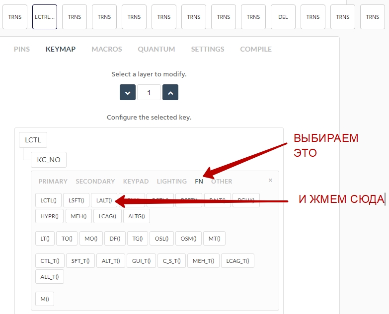
Next operation:
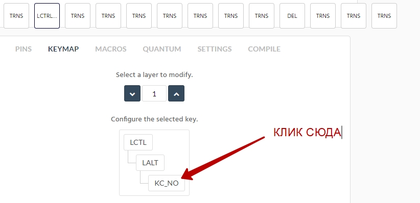
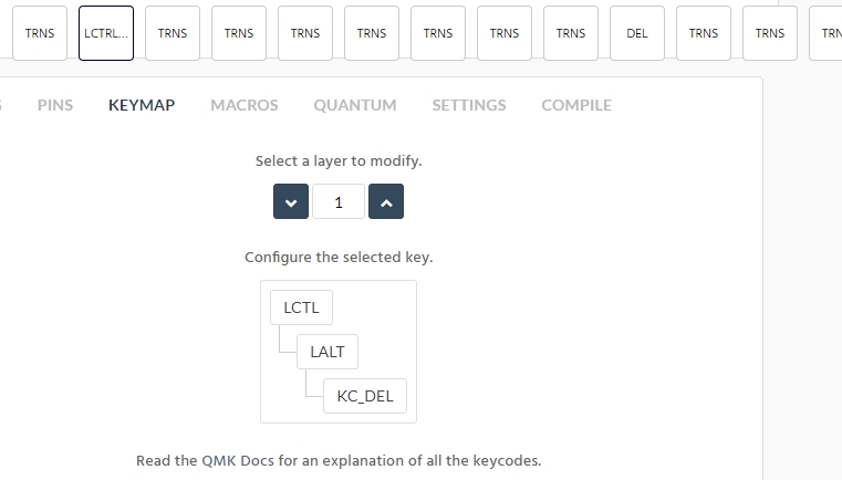
Finally, the button itself:

It should look like this:
And you can think of many such combinations.
Let's make the MO layer (2):
In the MO layer (2), I placed the F1 - F12 keys, the cursor keys and PgDn / PgUp / Home / End. Insert, like Caps Lock, I considered an unnecessary key and did not enter it myself.
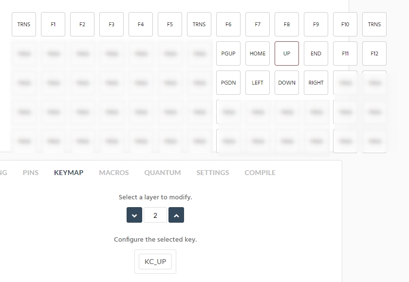
Thus, with the help of this layer, without moving my right palm at all, I can use the cursor keys and the PgDn / PgUp / Home / End block. Believe me, it's convenient! After that, you don't even want to look at ordinary standard keyboards.
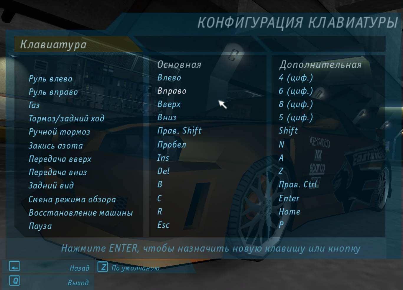
We all play computer games, one of my favorites is NFS Underground. Let's create a button layer just for this game! Naturally, holding the MO button (3) all the time during the game to steer with the cursor keys will be very inconvenient. Instead, we use the TG (3) modifier - it is similar to the principle of the Caps Lock key. Press the TG (3) key and release - the keyboard remains in the TG layer (3) mode. Press and release this key again - the keyboard will return to the default layer mode. It's that simple. For example, let's imagine that the game does not allow changing the keys, but we want to customize it for ourselves more conveniently.
I made myself like this:
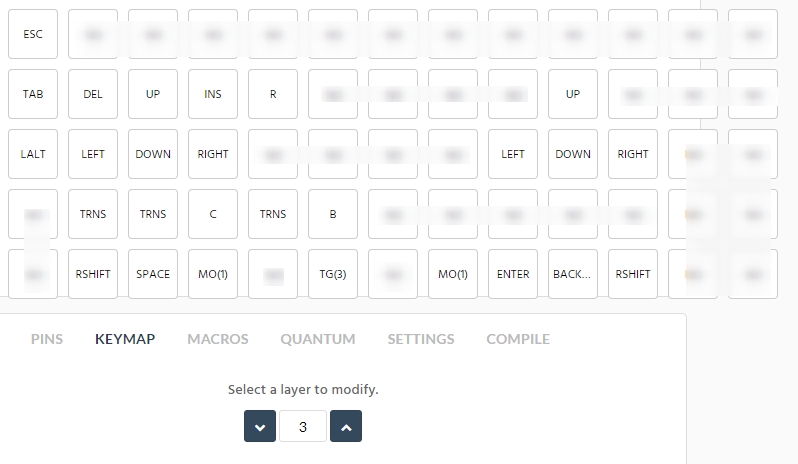
For convenience, I blurred the unused buttons on the screenshot. On both halves of the keyboard I made cursor keys - in case the hand gets numb and wants to give it a rest. I did not forget to implement the TG key (3) in this layer - so that you can return from this layer to the default layer. I also made the MO key (1) in layer 3 - to control the multimedia buttons. Well, the rest, in principle, is clear. Obviously, with such a layer of buttons it will definitely be more comfortable to play.
Let's go further. A total of 15 layers can be made. It's hard for me to imagine how all of them can be used. It's even harder to imagine how to remember them all. I currently only use 4 layers and so far they are enough.
I told you only about a small part of the ways to customize the firmware. But what I told you is already enough for you to start working more effectively with the keyboard. If you want to "stuff" your keyboard more - look there:
Key codes
How to save your work so that next time you don't start all over again:
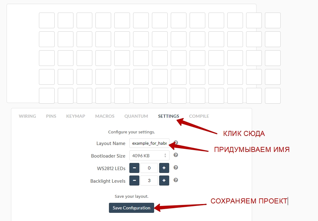
And now we can pick up the finished firmware from this tab:
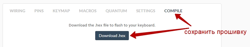
Now we need to upload the firmware to our arduino. It couldn't be easier.
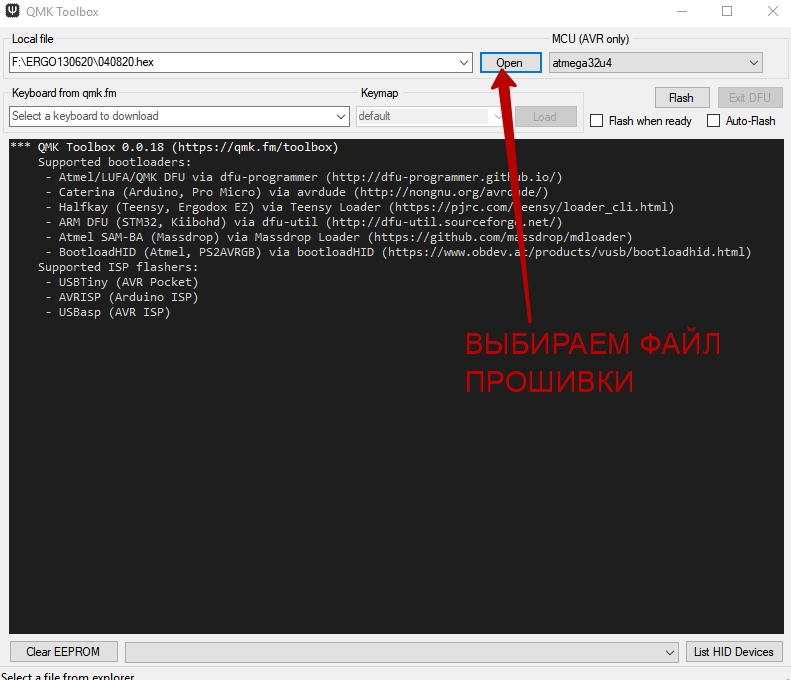
Follow the link: QMK Toolbox
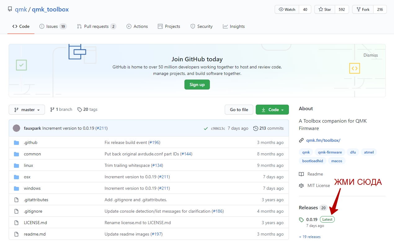
And now download the latest version of the program:
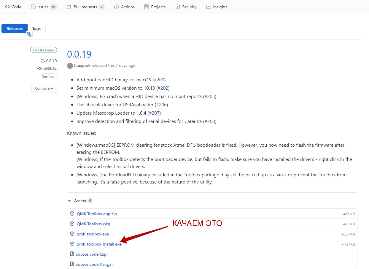
Install the program, just in case, reboot the computer
Now you will need to pick up a soldering iron and solder the button to the arduino with two wires to the GND and RESET contacts.
We connect our board with a micro usb cable to the computer - the LED on it should light up. We launch the QMK Toolbox program. We select the firmware file * .hex, which we recently downloaded.
Click on the button that we previously soldered to the arduino, and wait for the yellow line to appear on the dark background of the program. As soon as it appears, do not slow down and quickly press the FLASH button:
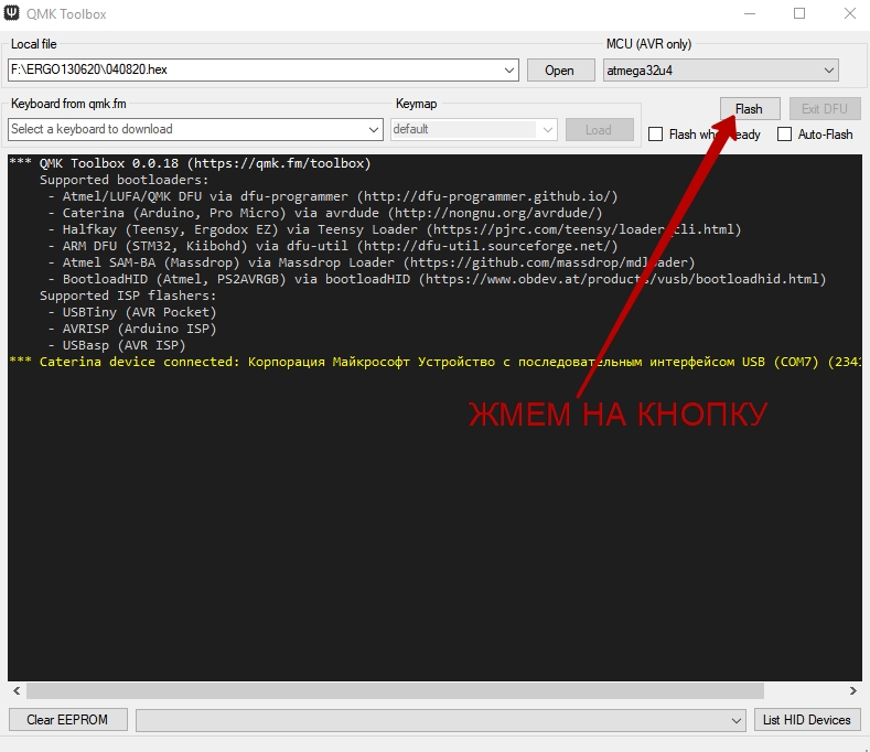
If you do slow down and the second yellow line appears, the FLASH button will not start flashing the board. Start over: press the soldered button, etc.
Moving on to soldering parts
It's time to tell you how to properly solder electronic components.
First you need to unsolder the diodes on the buttons. You will need to learn how to mark the diodes. Everything is simple here: the side of the diode, marked with a painted black ring, is the cathode, the other is the anode. What it is and why you need it you should have learned at school.
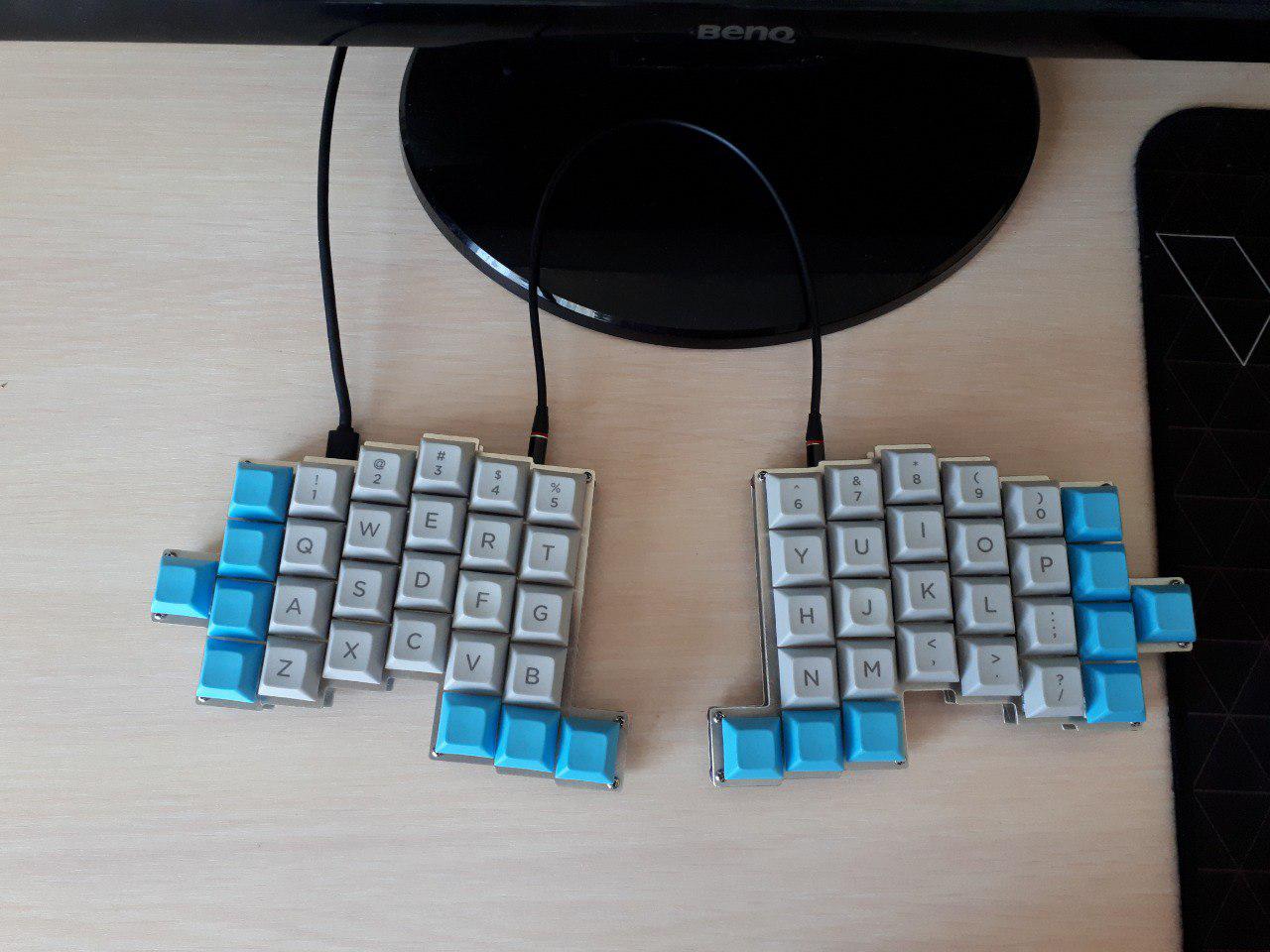
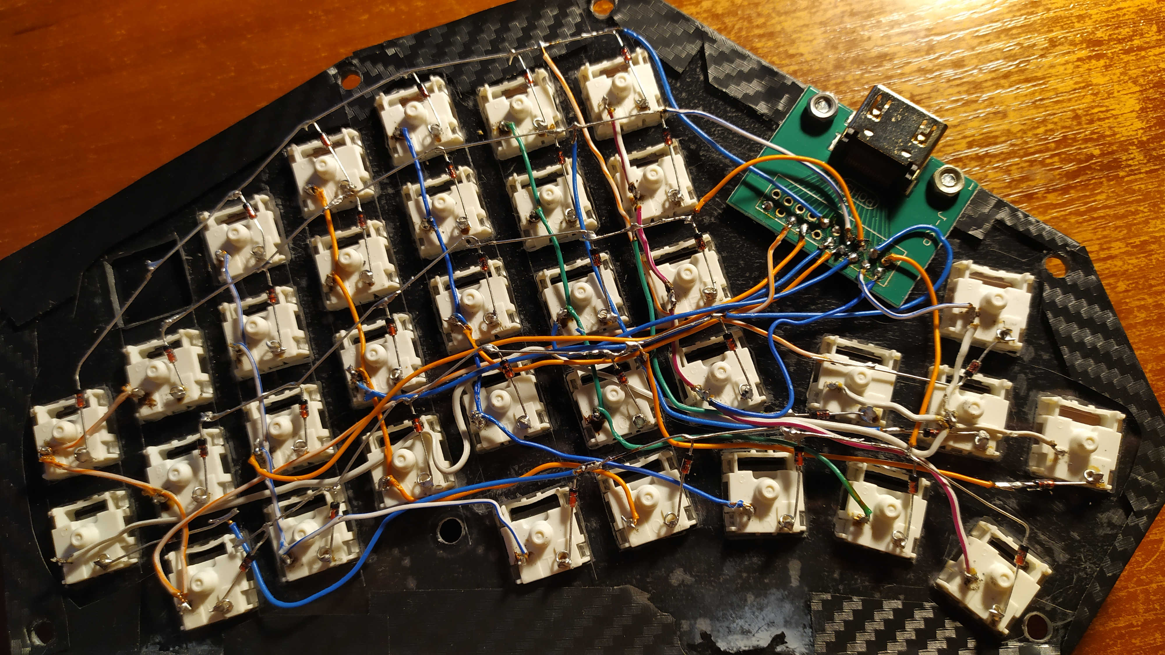
See what the left side of the keyboard
looks like : Now look at the photo below:

The upper row of ESCAPE keys, 1,2,3,4,5 we connected with diodes. We soldered the diodes to each other with cathodes, and the diodes themselves were soldered to the contacts of the buttons with anodes. We do the same with the row of buttons TAB, Q, W, E, R, T. This is the second row of buttons from the top. We solder the diodes together with cathodes, in general, in the same way as the upper row of buttons. We solder the remaining rows with diodes in the same way. Next, we solder the wires as in the photo below.

I specially soldered with multi-colored wires from the twisted pair cable so that you can easily figure it out. Take a close look at the right edge of the photo. I connected the free contacts of the VERTICAL ROW of keys with a blue wire: ESCAPE, TAB, ALT, CTRL, TG (3). We do exactly the same with the rest of the vertical rows.
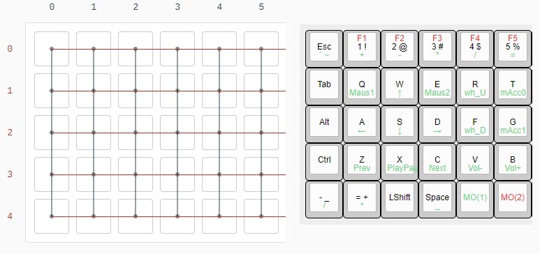
When you solder all this, you can proceed to connecting the arduina. Let's remember this picture:
And compare it with this picture:
We connect the wire connecting the vertical row of ESCAPE, TAB, ALT, CTRL, TG keys (3) with a wire to the arduino C6 contact. The wire connecting the vertical row of keys 1, Q, A, Z, TG (4) is connected with a wire to the arduino D7 contact. We connect the wire connecting the vertical row of keys 2, W, S, X, LShift with a wire to the arduino E6 contact. Next, we proceed by analogy. Moving on to the lines. The soldered cathodes of the diodes of the ESCAPE line, 1,2,3,4,5 are connected to the arduino contact D3. The soldered cathodes of diodes of the TAB, Q, W, E, R, T lines are connected to the arduino contact D2. We connect the diode cathodes of the Alt, A, S, D, F, G lines to the D1 contact. And then the same. The right half of the keyboard is prepared similarly to the left.

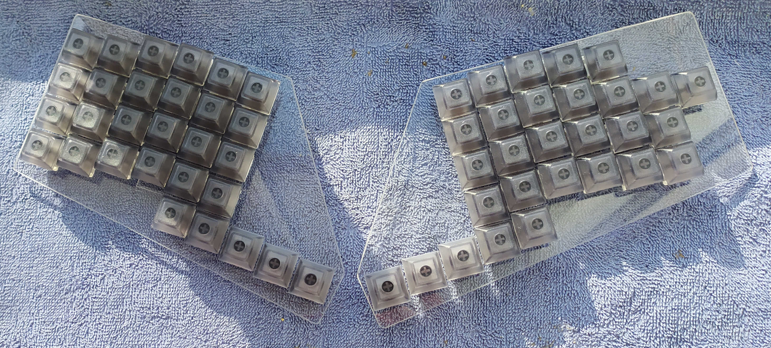
If not for the arrow keys, the photo below would not be so confusing:
But we already know that in fact everything is simple - we connect the rows of buttons with diodes, and the columns of buttons with wires according to the diagram in front of this photo. And how to connect this keyboard block, you should already understand yourself.
The cathodes of diodes of the line UP, 6,7,8,9,0,] soldered together, are connected to the arduino contact D3. The cathodes of the diodes of the DOWN, Y, U, I, O, P, [lines, soldered to each other, are connected to the arduino contact D2. Etc. We connect the wire connecting the vertical row of UP, DOWN, LEFT, RIGHT keys with a wire to the arduino B2 contact. The wire connecting the vertical row of keys 6, Y, H, N, MO (1) is connected with a wire to the arduino contact B3. And again, by analogy.
When you assemble the structure, launch Notepad on your computer and check how the buttons work. My keyboard did not want to work normally from the first or the second time - I mixed up the wires, soldering them not to my arduino contacts. It was also that I, inaccurately, whitened them among myself. It's easy to fix - take a multimeter and ring the wires, which one leads to. Just open these pictures on the monitor screen in front of you and check where the wires actually lead.
That's all. Based on this article, you can easily make for yourself a keyboard, sharpened for you and convenient for you personally. The kind of keyboard that you can't buy for any money anywhere and ever.
PS If you decide to make your own keyboard, do not hesitate - share your experience! I am always very interested in looking at new ideas. Perhaps thanks to you I can add something new and cool to my keyboard.