Start: assembly, input system, display.
Continued: drive, battery, sound.
Part 7: Text
Now that we're done with the Odroid Go layer of code, we can start building the game itself.
Let's start by drawing text on the screen because this will be a smooth introduction to several topics that will be useful in the future.
This part will be slightly different from the previous ones because there is very little code that runs on Odroid Go. Most of the code will be related to our first tool.
Tiles
In our rendering system, we will use tiles . We'll split the 320x240 screen into a grid of tiles, each containing 16x16 pixels. This will create a grid that is 20 tiles wide and 15 tiles high.
Static elements such as backgrounds and text will be rendered using the tile system, while dynamic elements such as sprites will be rendered differently. This means that backgrounds and text can only be placed in fixed locations, while sprites can be placed anywhere on the screen.
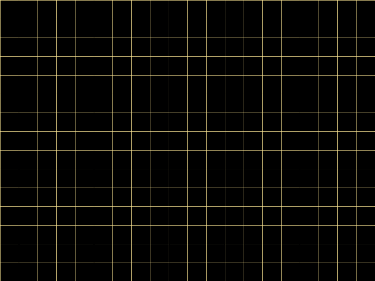
One 320x240 frame, as shown above, can contain 300 tiles. Yellow lines show the boundaries between tiles. Each tile will have a texture symbol or background element.
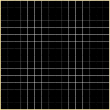
The zoomed image of a single tile shows the constituent 256 pixels separated by gray lines.
Font
Typically a TrueType font is used when rendering fonts on desktop computers . The font consists of glyphs that represent characters.
To use a font, you load it using a library (such as FreeType ) and create a font atlas containing bitmap versions of all the glyphs, which are then sampled upon rendering. This usually happens beforehand, not in the game itself.
In the game, GPU memory stores one texture with a rasterized font and a description in code that allows you to determine where the desired glyph is located in the texture. The text rendering process consists of rendering a portion of the texture with a glyph onto a simple 2D quad.
However, we take a different approach. Instead of fighting with TTF files and libraries, we'll create our own simple font.
The point of a traditional font system like TrueType is to be able to render a font at any size or resolution without modifying the original font file. This is accomplished by describing the font with mathematical expressions.
But we don't need such versatility, we know the display resolution and the font size we need, so we can rasterize our own font manually.
For this I created a simple 39 character font. Each symbol occupies one 16x16 tile. I'm not a professional type designer, but the result suits me perfectly.
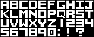
The original image is 160x64, but here I've doubled the scale for easy viewing.
Of course, this will prevent us from writing text in languages that do not use the 26 letters of the English alphabet....
Encode the glyph
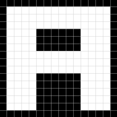
Looking at the example for the “A” glyph, we can see that it is sixteen lines of sixteen pixels long. In each line, a pixel is either on or off. We can use this feature to encode a glyph without having to load the font bitmap into memory in the traditional way.
Each pixel in a line can be thought of as one bit, that is, a line contains 16 bits. If the pixel is on, then the bit is on, and vice versa. That is, the fretboard encoding can be stored as sixteen 16-bit integers.
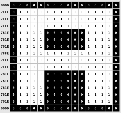
In this scheme, the letter “A” is encoded with the image shown above. The numbers on the left represent the 16-bit string value.
The complete glyph is encoded in 32 bytes (2 bytes per line x 16 lines). It takes 1248 bytes to encode all 39 characters.
Another way to solve the problem was to save the image file to the Odroid Go SD card, load it into memory on initialization, and then reference it when rendering text to find the glyph you want.
But the image file will have to use at least one byte per pixel (0x00 or 0x01), so the minimum image size will be (uncompressed) 10240 bytes (160 x 64).
In addition to saving memory, our method allows us to quite trivially encode the byte arrays of the font glyphs directly into the source code so that we do not have to load them from the file.
I'm pretty sure the ESP32 could handle loading an image into memory and referencing it at runtime, but I liked the idea of encoding tiles directly into arrays like this. It is very similar to how it is implemented on the NES.
The importance of writing tools
The game must run in real time at a rate of at least 30 frames per second. This means that everything in the game should be processed in 1 / 30th of a second, which is about 33 milliseconds.
To help achieve this goal, it is best to pre-process the data whenever possible so that the data can be used in the game without any processing. It also saves memory and storage space.
Often there is some kind of resource pipeline that takes the raw data exported from the content creation tool and transforms it into a form that is better suited to play in the game.
In the case of our font, we have a character set created in Asepritewhich can be exported as a 160x64 image file.
Instead of loading an image into memory when the game starts, we can create a tool to transform the data into a more space- and runtime-optimized form described in the previous section.
Font processing tool
We have to convert each of the 39 glyphs in the original image to byte arrays describing the state of their constituent pixels (as in the “A” example).
We can put an array of preprocessed bytes into a header file that is compiled into the game and written to its Flash drive. ESP32 has a lot more Flash memory than RAM, so we can take advantage of this by compiling as much information as possible into the game binary.
For the first time, we can do the pixel-to-byte conversion by hand and it will be quite doable (albeit boring). But if we want to add a new glyph or change an old one, the process becomes monotonous, time-consuming and error-prone.
And this is a good opportunity to create a tool.
The tool will load an image file, generate a byte array for each of the characters, and write them to a header file that we can compile into the game. If we want to change the glyphs of the font (which I have done many times) or add a new one, then we simply re-run the tool.
The first step is to export the glyph set from Aseprite in a format that our tool can read easily. We use the BMP file format because it has a simple header, does not compress the image, and allows the image to be encoded in 1 byte per pixel.
In Aseprite, I created an image with an indexed palette, so each pixel is one byte representing the index of the palette containing only black (Index 0) and white (Index 1) colors. The exported BMP file retains this encoding: a disabled pixel has byte 0x0, and an enabled pixel has byte 0x1.
Our tool will receive five parameters:
- BMP exported from Aseprite
- Text file describing the glyph scheme
- Path to the generated output file
- Width of each glyph
- Height of each glyph
The glyph schema description file is needed to map the visual information of the image to the characters themselves in the code.
The description of the exported font image looks like this:
ABCDEFGHIJ
KLMNOPQRST
UVWXYZ1234
567890:!?
It must match the schema in the image.
if (argc != 6)
{
	fprintf(stderr, "Usage: %s <input image> <layout file> <output header> <glyph width> <glyph height>\n", argv[0]);

	return 1;
}

const char* inFilename = argv[1];
const char* layoutFilename = argv[2];
const char* outFilename = argv[3];
const int glyphWidth = atoi(argv[4]);
const int glyphHeight = atoi(argv[5]);
The first thing we do is simple validation and parsing of the command line arguments.
FILE* inFile = fopen(inFilename, "rb");
assert(inFile);

#pragma pack(push,1)
struct BmpHeader
{
	char magic[2];
	uint32_t totalSize;
	uint32_t reserved;
	uint32_t offset;
	uint32_t headerSize;
	int32_t width;
	int32_t height;
	uint16_t planes;
	uint16_t depth;
	uint32_t compression;
	uint32_t imageSize;
	int32_t horizontalResolution;
	int32_t verticalResolution;
	uint32_t paletteColorCount;
	uint32_t importantColorCount;
} bmpHeader;
#pragma pack(pop)

// Read the BMP header so we know where the image data is located
fread(&bmpHeader, 1, sizeof(bmpHeader), inFile);
assert(bmpHeader.magic[0] == 'B' && bmpHeader.magic[1] == 'M');
assert(bmpHeader.depth == 8);
assert(bmpHeader.headerSize == 40);

// Go to location in file of image data
fseek(inFile, bmpHeader.offset, SEEK_SET);

// Read in the image data
uint8_t* imageBuffer = malloc(bmpHeader.imageSize);
assert(imageBuffer);
fread(imageBuffer, 1, bmpHeader.imageSize, inFile);

int imageWidth = bmpHeader.width;
int imageHeight = bmpHeader.height;

fclose(inFile);
The image file is read first.
The BMP file format has a header that describes the contents of the file. In particular, the width and height of the image are important to us, as well as the offset in the file where the image data starts.
We'll create a struct describing the schema of this header so that the header can be loaded and the values we want can be accessed by name. The pragma pack line ensures that no padding bytes are added to the struct so that when the header is read from the file, it matches correctly.
The BMP format is a little strange in that the bytes after the offset can vary greatly depending on the BMP specification used (Microsoft has updated it many times). With headerSizewe check which version of the header is in use.
We check that the first two bytes of the header are equal to BM , because that means it is a BMP file. Next, we check that the bit depth is 8 because we expect each pixel to be one byte. We also check that the header is 40 bytes, because that means the BMP file is the version we want.
The image data is loaded into the imageBuffer after fseek is called to go to the location of the image data specified by offset .
FILE* layoutFile = fopen(layoutFilename, "r");
assert(layoutFile);


// Count the number of lines in the file
int layoutRows = 0;
while (!feof(layoutFile))
{
	char c = fgetc(layoutFile);

	if (c == '\n')
	{
		++layoutRows;
	}
}


// Return file position indicator to start
rewind(layoutFile);


// Allocate enough memory for one string pointer per row
char** glyphLayout = malloc(sizeof(*glyphLayout) * layoutRows);
assert(glyphLayout);


// Read the file into memory
for (int rowIndex = 0; rowIndex < layoutRows; ++rowIndex)
{
	char* line = NULL;
	size_t len = 0;

	getline(&line, &len, layoutFile);


	int newlinePosition = strlen(line) - 1;

	if (line[newlinePosition] == '\n')
	{
		line[newlinePosition] = '\0';
	}


	glyphLayout[rowIndex] = line;
}

fclose(layoutFile);
We read the glyph schema description file into an array of strings that we need below.
First, we count the number of lines in the file to know how much memory needs to be allocated for the lines (one pointer per line), and then we read the file into memory.
Line breaks are truncated so that they do not increase the length of the line in characters.
fprintf(outFile, "int GetGlyphIndex(char c)\n");
fprintf(outFile, "{\n");
fprintf(outFile, "	switch (c)\n");
fprintf(outFile, "	{\n");

int glyphCount = 0;
for (int row = 0; row < layoutRows; ++row)
{
	int glyphsInRow = strlen(glyphLayout[row]);

	for (int glyph = 0; glyph < glyphsInRow; ++glyph)
	{
		char c = glyphLayout[row][glyph];

		fprintf(outFile, "		");

		if (isalpha(c))
		{
			fprintf(outFile, "case '%c': ", tolower(c));
		}

		fprintf(outFile, "case '%c': { return %d; break; }\n", c, glyphCount);

		++glyphCount;
	}
}

fprintf(outFile, "		default: { assert(NULL); break; }\n");
fprintf(outFile, "	}\n");
fprintf(outFile, "}\n\n");
We generate a function called GetGlyphIndex that takes a character and returns the data index of that character in the glyph map (which we will generate shortly).
The tool iteratively walks through the previously read schema description and generates a switch statement that matches the character to the index. It allows you to bind lowercase and uppercase characters to the same value and generates an assert if you try to use a character that is not a glyph map character.
fprintf(outFile, "static const uint16_t glyphMap[%d][%d] =\n", glyphCount, glyphHeight);
fprintf(outFile, "{\n");

for (int y = 0; y < layoutRows; ++y)
{
	int glyphsInRow = strlen(glyphLayout[y]);

	for (int x = 0; x < glyphsInRow; ++x)
	{
		char c = glyphLayout[y][x];

		fprintf(outFile, "	// %c\n", c);
		fprintf(outFile, "	{\n");
		fprintf(outFile, "	");

		int count = 0;

		for (int row = y * glyphHeight; row < (y + 1) * glyphHeight; ++row)
		{
			uint16_t val = 0;

			for (int col = x * glyphWidth; col < (x + 1) * glyphWidth; ++col)
			{
				// BMP is laid out bottom-to-top, but we want top-to-bottom (0-indexed)
				int y = imageHeight - row - 1;

				uint8_t pixel = imageBuffer[y * imageWidth + col];

				int bitPosition = 15 - (col % glyphWidth);
				val |= (pixel << bitPosition);
			}

			fprintf(outFile, "0x%04X,", val);
			++count;

			// Put a newline after four values to keep it orderly
			if ((count % 4) == 0)
			{
				fprintf(outFile, "\n");
				fprintf(outFile, "	");
				count = 0;
			}
		}

		fprintf(outFile, "},\n\n");
	}
}

fprintf(outFile, "};\n");
Finally, we generate the 16-bit values ourselves for each of the glyphs.
We traverse the characters from the description from top to bottom, left to right, and then create sixteen 16-bit values for each glyph by traversing its pixels in the image. If a pixel is enabled, then the code writes to the bit position of this pixel 1, otherwise - 0.
Unfortunately, the code of this tool is rather ugly due to the many calls to fprintf , but I hope that the meaning of what is happening in it is clear.
The tool can then be run to process the exported font image file:
./font_processor font.bmp font.txt font.h 16 16And it generates the following (shortened) file:
static const int GLYPH_WIDTH = 16;
static const int GLYPH_HEIGHT = 16;


int GetGlyphIndex(char c)
{
	switch (c)
	{
		case 'a': case 'A': { return 0; break; }
		case 'b': case 'B': { return 1; break; }
		case 'c': case 'C': { return 2; break; }

		[...]

		case '1': { return 26; break; }
		case '2': { return 27; break; }
		case '3': { return 28; break; }

		[...]

		case ':': { return 36; break; }
		case '!': { return 37; break; }
		case '?': { return 38; break; }
		default: { assert(NULL); break; }
	}
}

static const uint16_t glyphMap[39][16] =
{
	// A
	{
	0x0000,0x7FFE,0x7FFE,0x7FFE,
	0x781E,0x781E,0x781E,0x7FFE,
	0x7FFE,0x7FFE,0x781E,0x781E,
	0x781E,0x781E,0x781E,0x0000,
	},

	// B
	{
	0x0000,0x7FFC,0x7FFE,0x7FFE,
	0x780E,0x780E,0x7FFE,0x7FFE,
	0x7FFC,0x780C,0x780E,0x780E,
	0x7FFE,0x7FFE,0x7FFC,0x0000,
	},

	// C
	{
	0x0000,0x7FFE,0x7FFE,0x7FFE,
	0x7800,0x7800,0x7800,0x7800,
	0x7800,0x7800,0x7800,0x7800,
	0x7FFE,0x7FFE,0x7FFE,0x0000,
	},


	[...]


	// 1
	{
	0x0000,0x01E0,0x01E0,0x01E0,
	0x01E0,0x01E0,0x01E0,0x01E0,
	0x01E0,0x01E0,0x01E0,0x01E0,
	0x01E0,0x01E0,0x01E0,0x0000,
	},

	// 2
	{
	0x0000,0x7FFE,0x7FFE,0x7FFE,
	0x001E,0x001E,0x7FFE,0x7FFE,
	0x7FFE,0x7800,0x7800,0x7800,
	0x7FFE,0x7FFE,0x7FFE,0x0000,
	},

	// 3
	{
	0x0000,0x7FFE,0x7FFE,0x7FFE,
	0x001E,0x001E,0x3FFE,0x3FFE,
	0x3FFE,0x001E,0x001E,0x001E,
	0x7FFE,0x7FFE,0x7FFE,0x0000,
	},


	[...]


	// :
	{
	0x0000,0x0000,0x3C00,0x3C00,
	0x3C00,0x3C00,0x0000,0x0000,
	0x0000,0x0000,0x3C00,0x3C00,
	0x3C00,0x3C00,0x0000,0x0000,
	},

	// !
	{
	0x0000,0x3C00,0x3C00,0x3C00,
	0x3C00,0x3C00,0x3C00,0x3C00,
	0x3C00,0x3C00,0x0000,0x0000,
	0x3C00,0x3C00,0x3C00,0x0000,
	},

	// ?
	{
	0x0000,0x7FFE,0x7FFE,0x7FFE,
	0x781E,0x781E,0x79FE,0x79FE,
	0x01E0,0x01E0,0x0000,0x0000,
	0x01E0,0x01E0,0x01E0,0x0000,
	},
};
, switch , GetGlyphIndex O(1), , , 39 if.
, . - .
, .
-, char c int, .
Once we populate the font.h file with the glyph byte arrays, we can start drawing them to the screen.
static const int MAX_GLYPHS_PER_ROW = LCD_WIDTH / GLYPH_WIDTH;
static const int MAX_GLYPHS_PER_COL = LCD_HEIGHT / GLYPH_HEIGHT;

void DrawText(uint16_t* framebuffer, char* string, int length, int x, int y, uint16_t color)
{
	assert(x + length < MAX_GLYPHS_PER_ROW);
	assert(y < MAX_GLYPHS_PER_COL);

	for (int charIndex = 0; charIndex < length; ++charIndex)
	{
		char c = string[charIndex];

		if (c == ' ')
		{
			continue;
		}

		int xStart = GLYPH_WIDTH * (x + charIndex);
		int yStart = GLYPH_HEIGHT * y;

		for (int row = 0; row < GLYPH_HEIGHT; ++row)
		{
			for (int col = 0; col < GLYPH_WIDTH; ++col)
			{
				int bitPosition = 1U << (15U - col);
				int glyphIndex = GetGlyphIndex(c);

				uint16_t pixel = glyphMap[glyphIndex][row] & bitPosition;

				if (pixel)
				{
					int screenX = xStart + col;
					int screenY = yStart + row;

					framebuffer[screenY * LCD_WIDTH + screenX] = color;
				}
			}
		}
	}
}
Since we transferred the main load to our tool, the text rendering code itself will be quite simple.
To render a string, we loop through its constituent characters and skip a character if we encounter a space.
For each non-space character, we get the glyph index in the glyph map so that we can get its byte array.
To check the pixels in a glyph, we loop through 256 of its pixels (16x16) and check the value of each bit in each line. If the bit is on, then we write the color for this pixel to the frame buffer. If it is not enabled, then we do nothing.
It is generally not worth writing data to a header file because if that header is included in multiple source files, the linker will complain about multiple definitions. But font.h will only be included in the code by the text.c file , so it won't cause problems.
Demo
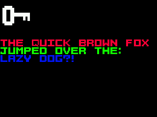
We will test rendering text by rendering the famous pangram The Quick Brown Fox Jumped Over The Lazy Dog , which uses all the characters supported by the font.
DrawText(gFramebuffer, "The Quick Brown Fox", 19, 0, 5, SWAP_ENDIAN_16(RGB565(0xFF, 0, 0)));
DrawText(gFramebuffer, "Jumped Over The:", 16, 0, 6, SWAP_ENDIAN_16(RGB565(0, 0xFF, 0)));
DrawText(gFramebuffer, "Lazy Dog?!", 10, 0, 7, SWAP_ENDIAN_16(RGB565(0, 0, 0xFF)));
We call DrawText three times to make the lines appear on different lines, and increment the Tile Y coordinate for each so that each line is drawn below the previous one. We will also set a different color for each line to test the colors.
For now, we calculate the length of the string manually, but in the future we will get rid of this hassle.
Links
- Bitmap file header
Part 8: the tile system
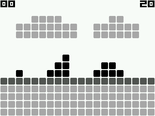
As mentioned in the previous part, we will be creating game backgrounds from tiles. The dynamic objects in front of the background will be sprites , which we'll look at later. Examples of sprites are enemies, bullets, and the player character.
We will place 16x16 tiles on a 320x240 screen in a fixed 20x15 grid. At any given time, we will be able to display up to 300 tiles on the screen.
Tile Buffer
To store tiles, we should use static arrays, not dynamic memory, so as not to worry about malloc and free , memory leaks and memory shortages when allocating it (Odroid is an embedded system with a limited amount of memory).
If we want to store the layout of tiles on the screen, and the total tiles are 20x15, then we can use a 20x15 array, in which each element is a tile index in the "map". The tilemap contains the tile graphics itself.
In this diagram, the numbers on top represent the X coordinate of the tile (in tiles), and the numbers on the left represent the Y coordinate of the tile (in tiles).
In code, it can be represented like this:
uint8_t tileBuffer[15][20];The problem with this solution is that if we wanted to change what is displayed on the screen (by changing the contents of the tile), then the player will see the replacement tile.
This can be solved by expanding the buffer area so that you can write to it while it is off-screen, and when displayed, it looks continuous.
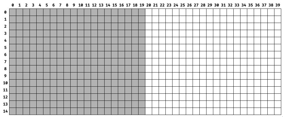
The gray squares indicate the visible "window" in the tile buffer, which is rendered on the screen. While the screen displays what is in the gray squares, the contents of all the white squares can be changed so that the player does not see it.
In code, this can be thought of as an array twice the size in X.
uint8_t tileBuffer[15][40];Selecting a palette
For now, we'll be using a palette of four grayscale values.
In RGB888 format, they look like:
- 0xFFFFFF (white / 100% value).
- 0xABABAB (- / 67% )
- 0x545454 (- / 33% )
- 0x000000 ( / 0% )

We avoid using colors for now because I am still improving my artistic skills. By using grayscale, I can focus on contrast and shape without worrying about color theory. Even a small palette of colors requires good artistic taste.
If you are in doubt about the strength of 2-bit grayscale color, think of the Game Boy, which had only four colors in its palette. The first Game Boy screen was tinted green, so the four values were displayed as shades of green, but the Game Boy Pocket displayed them as true grayscale.
The image below for The Legend of Zelda: Link's Awakening shows how much you can achieve with just four values if you have a good artist.
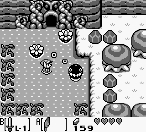
So far, the tile graphics will look like four squares with a one pixel border outside and with truncated corners. Each square will have one of the colors in our palette.
Truncating corners is a small change, but it allows you to distinguish between individual tiles, which is useful for rendering the mesh.

Palette tool
We will store the palette in the JASC Palette file format, which is easy to read, easy to parse with tools, and supported by Aseprite.
The palette looks like this
JASC-PAL
0100
4
255 255 255
171 171 171
84 84 84
0 0 0
The first two lines are found in every PAL file. The third line is the number of items in the palette. The rest of the lines are the values of the red, green and blue elements of the palette.
The palette tool reads the file, converts each color to RGB565, reverses the byte order, and writes the new values to the header file that contains the palette in an array.
The code for reading and writing the file is similar to the code used in the seventh article, and the color processing is done like this:
// Each line is of form R G B
for (int i = 0; i < paletteSize; ++i)
{
	getline(&line, &len, inFile);

	char* tok = strtok(line, " ");
	int red = atoi(tok);

	tok = strtok(NULL, " ");
	int green = atoi(tok);

	tok = strtok(NULL, " ");
	int blue = atoi(tok);

	uint16_t rgb565 =
		  ((red >> 3u) << 11u)
		| ((green >> 2u) << 5u)
		| (blue >> 3u);

	uint16_t endianSwap = ((rgb565 & 0xFFu) << 8u) | (rgb565 >> 8u);

	palette[i] = endianSwap;
}
The strtok function splits the string according to the delimiters. The three color values are separated by a single space, so we use that. We then create the RGB565 value by shifting the bits and reversing the byte order, as we did in the third part of the article.
./palette_processor grey.pal grey.hThe tool's output looks like this:
uint16_t palette[4] =
{
	0xFFFF,
	0x55AD,
	0xAA52,
	0x0000,
};
Tile processing tool
We also need a tool that outputs tile data in the format expected by the game. The value of each pixel in the BMP file is a palette index. We'll keep this indirect notation so that a 16x16 (256) byte tile takes up one byte per pixel. During the execution of the program, we will find the color of the tile in the palette.
The tool reads the file, traverses the pixels, and writes their indices to an array in the header.
The code for reading and writing the file is also similar to the code in the font processing tool, and the creation of the corresponding array occurs here:
for (int row = 0; row < tileHeight; ++row)
{
	for (int col = 0; col < tileWidth; ++col)
	{
		// BMP is laid out bottom-to-top, but we want top-to-bottom (0-indexed)
		int y =  tileHeight - row - 1;

		uint8_t paletteIndex = tileBuffer[y * tileWidth + col];

		fprintf(outFile, "%d,", paletteIndex);
		++count;

		// Put a newline after sixteen values to keep it orderly
		if ((count % 16) == 0)
		{
			fprintf(outFile, "\n");
			fprintf(outFile, "	");

			count = 0;
		}
	}
}
The index is obtained from the pixel position in the BMP file and then written to the file as a 16x16 array element.
./tile_processor black.bmp black.hThe tool's output when processing a black tile looks like this:
static const uint8_t tile[16][16] =
{
    0,0,0,0,0,0,0,0,0,0,0,0,0,0,0,0,
    0,0,3,3,3,3,3,3,3,3,3,3,3,3,0,0,
    0,3,3,3,3,3,3,3,3,3,3,3,3,3,3,0,
    0,3,3,3,3,3,3,3,3,3,3,3,3,3,3,0,
    0,3,3,3,3,3,3,3,3,3,3,3,3,3,3,0,
    0,3,3,3,3,3,3,3,3,3,3,3,3,3,3,0,
    0,3,3,3,3,3,3,3,3,3,3,3,3,3,3,0,
    0,3,3,3,3,3,3,3,3,3,3,3,3,3,3,0,
    0,3,3,3,3,3,3,3,3,3,3,3,3,3,3,0,
    0,3,3,3,3,3,3,3,3,3,3,3,3,3,3,0,
    0,3,3,3,3,3,3,3,3,3,3,3,3,3,3,0,
    0,3,3,3,3,3,3,3,3,3,3,3,3,3,3,0,
    0,3,3,3,3,3,3,3,3,3,3,3,3,3,3,0,
    0,3,3,3,3,3,3,3,3,3,3,3,3,3,3,0,
    0,0,3,3,3,3,3,3,3,3,3,3,3,3,0,0,
    0,0,0,0,0,0,0,0,0,0,0,0,0,0,0,0,
};
If you look closely, you can understand the appearance of a tile simply by the indices. Every 3 means black and every 0 means white.
Frame window
As an example, we can create a simple (and extremely short) "level" that fills the entire tile buffer. We have four different tiles, and not to worry about the graphics, we just use a scheme where each of the four tiles has a different color in grayscale.
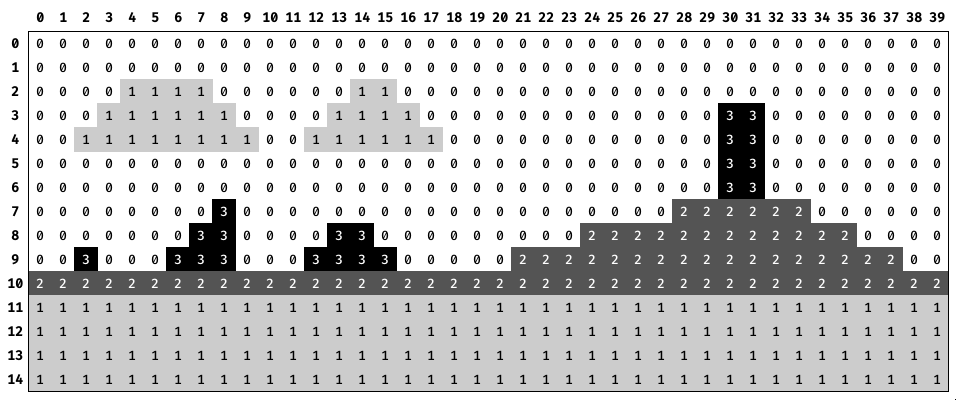
We arrange four tiles in a 40x15 level grid to test our system.
The numbers above indicate the column indexes of the framebuffer. The numbers below are the indexes of the frame window columns. The numbers on the left are the lines of each buffer (no vertical window movement).
For the player, everything will look as shown in the video above. When the window is moved to the right, it appears to the player that the background is shifted to the left.
Demo
The number in the upper left corner is the column number of the left edge of the tile buffer window, and the number in the upper right corner is the column number of the right edge of the tile buffer window.
Source
The source code for the entire project is here .